Geophysical Survey Systems MINIXT The StructureScan Mini XT is a GPR handheld analyzer User Manual GSSI StructureScan Mini XT Quick Start Guide
Geophysical Survey Systems, Inc. The StructureScan Mini XT is a GPR handheld analyzer GSSI StructureScan Mini XT Quick Start Guide
Users Manual
Copyright © 2015 Geophysical Survey Systems, Inc. MN70-812 Rev1
All Rights Reserved
StructureScan™ MiniXT
Quick Start Guide
A Fast Check List For Field Operation
Contents
Section 1: Getting Started.................................................................................................................................... 1
Section 2: Configuring the Structure Scan MiniXT in ScanEZ Mode ..................................................... 3
Section 3: Configuring the Structure Scan MiniXT in Scan3D Mode. .................................................... 4
Section 4: Configuring the Structure Scan MiniXT in System Settings. ................................................ 5
Appendix A: Inventory of Your System ........................................................................................................... 6
Appendix B: Battery/Charger Information ..................................................................................................... 7
Appendix C: Sample Data .................................................................................................................................... 9
Appendix D: Laser Information ........................................................................................................................ 13
Laser Information: General ................................................................................................................................ 13
Laser Information: Specific for the StructureScan Mini ........................................................................... 13

Limited Warranty, Limitations of Liability and Restrictions
Geophysical Survey Systems, Inc. hereinafter referred to as GSSI, warrants that for a period of 24 months from the delivery date to the
original purchaser this product will be free from defects in materials and workmanship. EXCEPT FOR THE FOREGOING LIMITED
WARRANTY, GSSI DISCLAIMS ALL WARRANTIES, EXPRESS OR IMPLIED, INCLUDING ANY WARRANTY OF
MERCHANTABILITY OR FITNESS FOR A PARTICULAR PURPOSE. GSSI's obligation is limited to repairing or replacing parts
or equipment which are returned to GSSI, transportation and insurance pre-paid, without alteration or further damage, and which in
GSSI's judgment, were defective or became defective during normal use.
GSSI ASSUMES NO LIABILITY FOR ANY DIRECT, INDIRECT, SPECIAL, INCIDENTAL OR CONSEQUENTIAL
DAMAGES OR INJURIES CAUSED BY PROPER OR IMPROPER OPERATION OF ITS EQUIPMENT, WHETHER OR NOT
DEFECTIVE.
Before returning any equipment to GSSI, a Return Material Authorization (RMA) number must be obtained. Please call the GSSI
Customer Service Manager who will assign an RMA number. Be sure to have the serial number of the unit available.
Regulatory Information
Please see the GSSI Manual CD or our website, www.geophysical.com/regulatoryinformation.htm, for current information and FCC
Registration Form, including:
• FCC Notice for U.S. Customer
• Canadian Requirements for RSS-220
• Declaration of CE Conformance
Laser Cautions and Warnings
Please see Appendix D for important laser cautions and warnings.
Quick Start Guide StructureScan™ MiniXT
Geophysical Survey Systems, Inc. 1
Section 1: Getting Started
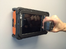
1 Preparing the StructureScan MiniXT.
• This section will describe removing the MiniXT from its shipping case, identifying the hardware components, and
inserting the battery.
Quick Start Guide StructureScan™ MiniXT
Geophysical Survey Systems, Inc.
2
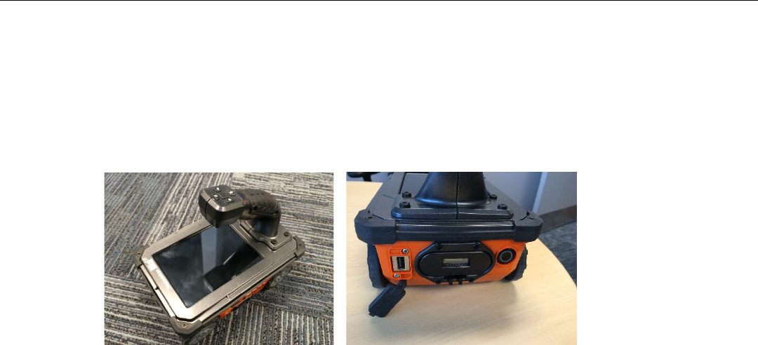
2 Powering up the StructureScan MiniXT.
• This section will describe the power up/down sequence of the MiniXT. It will introduce
the user to the splash screen as well as the battery and storage status icons.
• This section will describe the logic of the 5 hardkeys and the trigger button on the
handle.
Quick Start Guide StructureScan™ MiniXT
Geophysical Survey Systems, Inc.
3
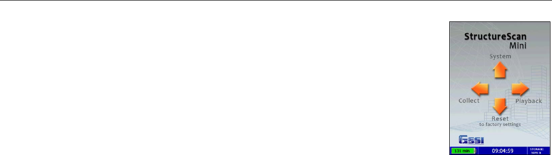
Section 2: Configuring the Structure Scan MiniXT
in ScanEZ Mode
Before collecting any data, you may want to configure your MiniXT.
This section describes selecting the ScanEZ mode for basic 2D concrete scanning and configuring
that mode with common collection parameters.
Splash Screen Menu Options
This section describes the function and how to access the Splash Screen options of Color Table,
Depth, and Concrete Type.
Collecting Data in ScanEZ Mode
This section describes the data collection procedure, discusses common issues, and provides
representative example data.
Playing Back Data in ScanEZ Mode
This section describes the use of Playback Mode.

Quick Start Guide StructureScan™ MiniXT
Geophysical Survey Systems, Inc.
4
Section 3: Configuring the Structure Scan MiniXT in Scan3D Mode.
This section describes the Scan3D mode.
Splash Screen Menu Options
This section describes the function and how to access the Splash Screen options of Color Table, Depth, Concrete Type,
and Grid Config options.
Collecting Data in Scan3D Mode
This section describes the data collection procedure for 3D grids of different sizes.
Playing Back Data in Scan3D Mode
This section describes the use of Playback Mode. It gives tips for optimizing the image and discusses some representative
data examples.

Quick Start Guide StructureScan™ MiniXT
Geophysical Survey Systems, Inc.
5
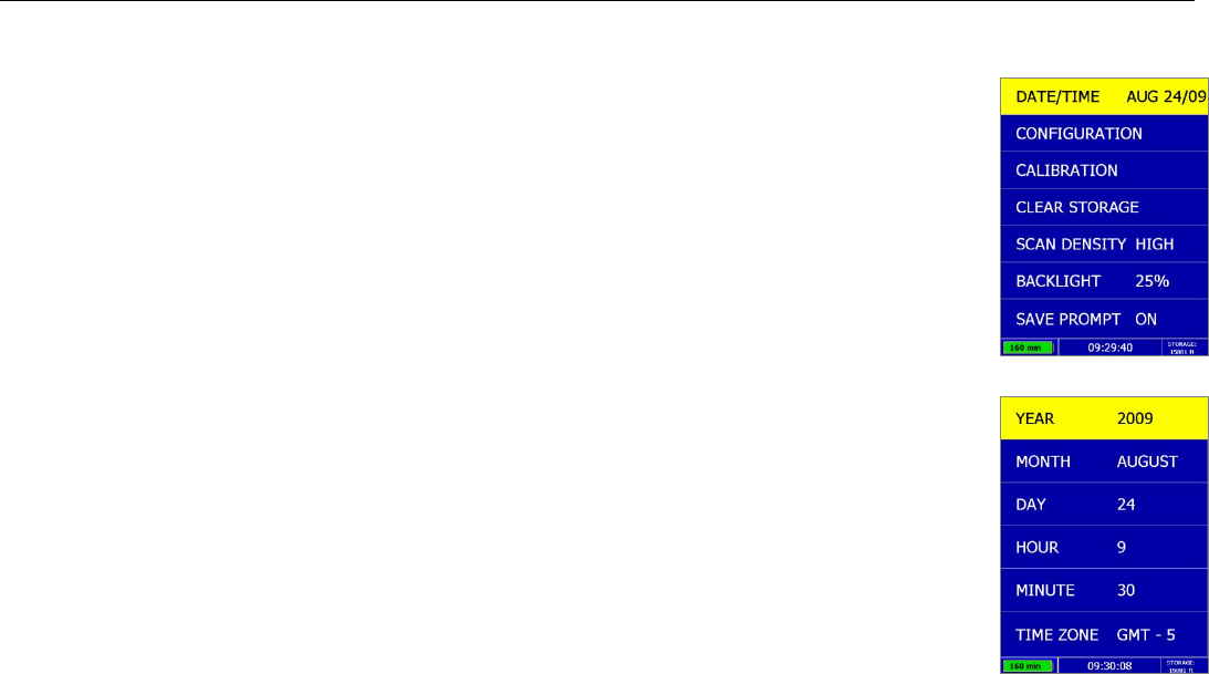
Section 4: Configuring the Structure Scan MiniXT in System Settings.
Date/Time: Configuring Date and Time
Instructions on setting the MiniXT’s clock.
Configuration: Configuring Orientation, Language, Units, Laser, and Sound
Instructions on setting common system-wide parameters and returning to factory defaults

Quick Start Guide StructureScan™ MiniXT
Geophysical Survey Systems, Inc.
6
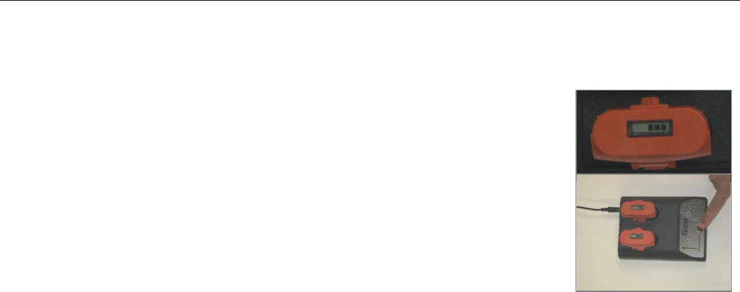
Appendix A: Inventory of Your System
• StructureScan MiniXT
• Battery charger (2 slots)
• Battery charger adapter
• International plugs for the battery charger adapter (3)
• Quick Start Guide (this manual)
• USB cable
• Batteries (2)
• GSSI wrist strap
• Training DVD
• Resource CD
• Transit case
Quick Start Guide StructureScan™ MiniXT
Geophysical Survey Systems, Inc.
7
Appendix B: Battery/Charger Information
Your system comes with a two-slotted battery charger and adapter. It also comes with
three international interchangeable plugs.
• To charge your batteries, simply attach the adapter to the charger and plug in the
adapter. Insert one or both batteries. The batteries will charge one at a time. The bars
located at the top of the batteries will indicate how much charge is left in the battery.
• At times, you may wish to re-calibrate a battery. Simply insert a battery into the slot
on the left and press the RECAL button
• LED Lights: As the batteries are charging, the LED lights for each slot will do different
things.
• No Lights – No Batteries
• Green Flash – Fast Charging
• Green Solid – Fully Charged
• Yellow Flash – Recalibrating
• Yellow/Green – Recalibrated
• Yellow Solid – Standby
• Red Flash – Error
• If the charger remains plugged in and there are NO batteries in the charger, the charger will eventually begin to
“beep.” Since this can be annoying, it is recommend that you unplug the charger when not in use.
Quick Start Guide StructureScan™ MiniXT
Geophysical Survey Systems, Inc.
8
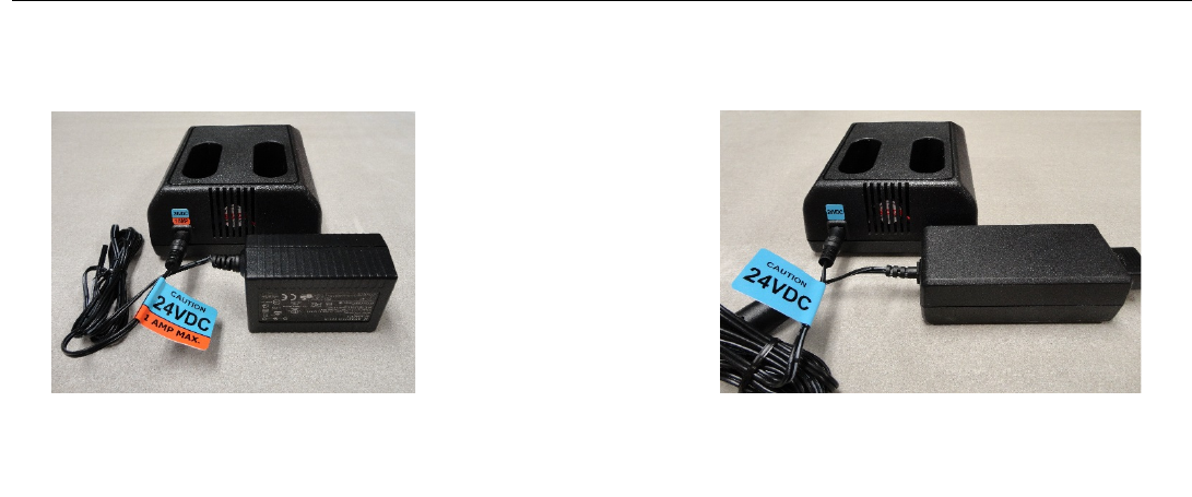
• If you own another GSSI system: Make sure that you are using the correct battery charger.
StructureScan Mini/Mini HR Charger
UtilityScan DF, Profiler, LifeLocator,
SIR 4000 Charger
Quick Start Guide StructureScan™ MiniXT
Geophysical Survey Systems, Inc.
9
Appendix C: Sample Data
These examples are presented for informational use only. Conditions may be different at your site that may cause the
images to look different from the data shown here.
Example 1 – Concrete Block Data
User Marks entered during collection to
identify the ends of each block (black lines)
Voids (2) within the blocks
Filled cell with rebar
Quick Start Guide StructureScan™ MiniXT
Geophysical Survey Systems, Inc.
10
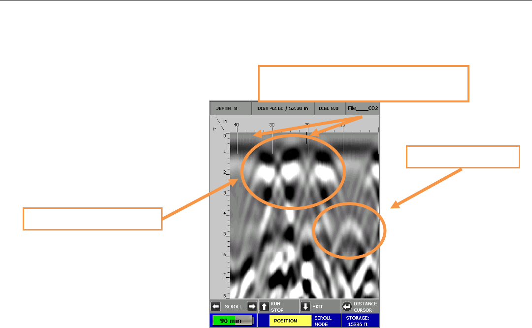
Example 2 – Rebar Data
This is an example of rebar. Note the distance between the peaks here (as well as at the location if you marked the area)
is approximately 8 inches. Also note the approximate depth, the brightness of the hyperbolas, and they tend to be at a
constant depth over the short term.
Quick Start Guide StructureScan™ MiniXT
Geophysical Survey Systems, Inc.
11
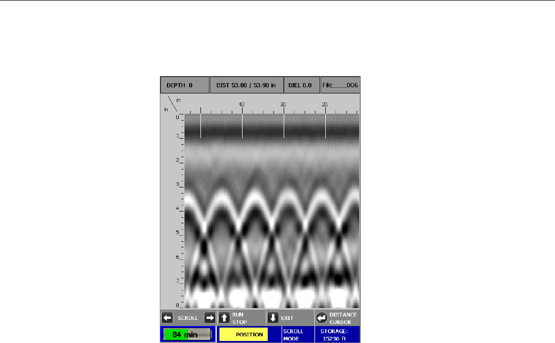
Example 3 – Mesh Data
This is an example of mesh. Note the distance between the peaks here (as well as at the location if you marked the area)
is approximately 6 inches. Also note the approximate depth, the brightness of the hyperbolas, and mesh may be more
uneven than rebar.
Quick Start Guide StructureScan™ MiniXT
Geophysical Survey Systems, Inc.
12
Example 4 – PVC
This is an example of two PVC pipes. Note they tend to be dimmer than rebar.
Quick Start Guide StructureScan™ MiniXT
Geophysical Survey Systems, Inc.
13
Appendix D: Laser Information
Laser Information: General
• Do not intentionally point the laser into your eye. Do not look directly into the laser
light source.
• Do not place the laser in a position that may cause anyone to stare into the laser beam
intentionally or unintentionally.
• Always power down the unit when not in use.
• Never view a laser through an optical device such a binoculars or a microscope.
Laser Information: Specific for the StructureScan Mini
• Do not remove or deface any product labels.
• This product contains lasers used as guides. Do not stare into any of the beams.
• You may configure the lasers on or off. From the Main menu:
a) Select Configure
b) Press and highlight Configuration and press
.
c) Press and highlight LASER
d) Press
to toggle the laser On or Off.

Quick Start Guide StructureScan™ MiniXT
Geophysical Survey Systems, Inc.
14
• This product is designed to be opened by Field Service Professionals employed and/or trained by Geophysical Survey
Systems, Inc only. Do not open this product. Tampering with this product voids all warranties.
• The laser has no serviceable parts.
• The laser will flash several times during system boot up.
• The laser will blink (whether Laser is configured On or Off) when the battery life is low (10%)
• Remove the battery whenever transporting the product.
• Remove the battery whenever doing any self maintenance to the product, such as cleaning the windows of the
lasers.
• If the lasers are configured On and the lasers are not working during collection of data, do not open the product. The
product must be serviced by an authorized GSSI employee or representative only.
• If the lasers are configured On, they will work only while in the Collect menu option.
• The lasers will remain on (if Laser is configured On) even if the unit goes into sleep mode.

Regulatory
Information
Regulatory Information
The use of GSSI antennas is governed by different regulatory agencies around the world. Specific antenna
models must be certified for legal operation in your country. Please read and understand the following
regulatory passages that pertain to your antenna. A listing of certified antennas by region can be found
www.geophysical.com/regulatoryinformation.htm.
Notice
Operation is subject to the following two conditions: (1) this device may not cause interference, and (2)
this device must accept any interference, including interference that may cause undesired operation of the
device.
Survey Wheels
All of GSSI’s antennas are designed to operate with survey wheels. Some antennas have built-in survey
wheels, including the 62000 Palm Antenna, the Mini-SIR and the MINIXT. The series of concrete
antennas, including the 5100, 5101 and 52600, have survey wheels built in to their special carts, the 614
and 615. The larger antennas, including the 3101D, 5103, 50400 and 5104 are used in the larger carts, the
623, 643 and 653, which have survey wheels built in to them. Various sizes of survey wheels can also be
attached directly to these antennas. This includes the 611, 620 and 622. For highway surveys we use the
630 Distance measuring Instrument (DMI).
Geophsyical Survey Systems, Inc. Regulatory Information
Garantie limitée, limites de responsabilité et restrictions
Geophysical Survey Systems, Inc, ci-après dénommé GSSI, garantit à l'acheteur original de ce produit
que, pendant une période de 24 mois à compter de la date de livraison, ce dernier sera exempt de défauts
de matériaux et de fabrication. EXCEPTE POUR CETTE GARANTIE LIMITÉE, GSSI REJETTE
TOUTE GARANTIE, EXPLICITE OU IMPLICITE, Y COMPRIS TOUTE GARANTIE DE QUALITE
MARCHANDE OU D'ADEQUATION A UN USAGE PARTICULIER. L’obligation de GSSI est limitée
à la réparation ou le remplacement de pièces ou équipements qui sont retournés à GSSI, transport et
assurance prépayés, sans altération ni d'autres dommages, et qui, d’après GSSI, étaient défectueux ou sont
devenus défectueux lors d’une utilisation normale.
GSSI N'ASSUME AUCUNE RESPONSABILITE POUR LES DOMMAGES DIRECTS, INDIRECTS,
SPÉCIAUX, INCIDENTS OU CONSEQUENTS OU BLESSURES CAUSEES PAR UNE BONNE OU
MAUVAISE UTILISATION DE SON EQUIPEMENT DÉFECTUEUX OU NON.
Avant de retourner tout équipement à GSSI, une autorisation de retour matériel (RMA) doit être obtenue.
Appelez s'il vous plaît le service clientèle GSSI qui attribuera un numéro de RMA. Soyez sûr d'avoir le
numéro de série de l'unité.
Informations réglementaires
L'utilisation des antennes GSSI est régie par différents organismes de réglementation à travers le monde.
Certains modèles d'antenne spécifiques doivent être certifiés pour un fonctionnement légal dans votre
pays. Merci de lire et comprendre les passages suivants de réglementation qui s'appliquent à votre
antenne. Une liste des antennes certifiées par région peut être trouvée sur www.geophysical.com /
regulatoryinformation.htm.
Avis
La mise en œuvre est soumise aux deux conditions suivantes: (1) cet appareil ne doit pas provoquer
d'interférences et (2) cet appareil doit accepter toute interférence, y compris les interférences qui peuvent
causer un fonctionnement non désiré de l'appareil.
Roues codeuses – Odomètres
Toutes les antennes GSSI sont conçus pour fonctionner avec des roues codeuses. Certaines antennes,
comprenant l'antenne 62000 Palm, le Mini-SIR et le MINIXT, intègrent directement les roues codeuses.
La série d'antennes pour le béton, comprenant les 5100, 5101 et 52600, ont des roues codeuses intégrées à
leurs chariots spéciaux, les 614 et 615. Les antennes plus grandes, telles que la 3101D, 5103, 50400 et
5104 sont utilisées dans les chariots plus grands, les 623, 643 et 653, qui ont des roues codeuses intégrées.
Différentes tailles de roues codeuses peuvent être également être fixées directement sur ces antennes,
comprenant les 611, 620 et 622. Pour les auscultations de chaussées nous utilisons l’odomètre 630 (DMI :
Distance Measuring Instrument).
FCC Notice (for U.S. Customers):
This device complies with part 15, class F of the FCC Rules:
Operation is subject to the following conditions:
1 This device many not cause harmful interference, and
2 This device must accept any interference received, including interference that may cause
undesired operation
Warning: Changes or modifications to this unit not expressly approved by the party responsible for
compliance could void the user’s authority to operate the equipment.
Operation of this device is restricted to law enforcement, fire and rescue officials, scientific research
institutes, commercial mining companies, construction companies and private parties operating on behalf
of these groups. Operation by any other party is a violation of 47 U.S.C. § 301 and could subject the
operator to serious legal penalties.
Coordination Requirements
(a) UWB imaging systems require coordination through the FCC before the equipment may be used. The
operator shall comply with any constraints on equipment usage resulting from this coordination.
(b) The users of UWB imaging devices shall supply detailed operational areas to the FCC Office of
Engineering and Technology who shall coordinate this information with the Federal Government through
the National Telecommunications and Information Administration. The information provided by the
UWB operator shall include the name, address and other pertinent contact information of the user, the
desired geographical area of operation, and the FCC ID number and other nomenclature of the UWB
device. This material shall be submitted to the following address:
Frequency Coordination Branch, OET
Federal Communications Commission
445 12th Street, SW
Washington, D.C. 20554
ATTN: UWB Coordination
(d) Users of authorized, coordinated UWB systems may transfer them to other qualified users and to
different locations upon coordination of change of ownership or location to the FCC and coordination
with existing authorized operations.
(e) The NTIA/FCC coordination report shall include any needed constraints that apply to day-to-day
operations. Such constraints could specify prohibited areas of operations or areas located near authorized
radio stations for which additional coordination is required before operation of the UWB equipment. If
additional local coordination is required, a local coordination contact will be provided.

For U.S. Customers
Ground Penetrating Radar Coordination Notice And Equipment Registration
Note: This form is only for Domestic United States users. The Federal Communications Commission
(FCC) requires that all users of GPR who purchased antennas after July 15th, 2002 register their
equipment and areas of operation. It is required that you fill out this form and fax or mail to the FCC.
Failure to do this is a violation of Federal law.
1. Date:
2. Company name:
3. Address:
4. Contact Information [contact name and phone number]:
5. Area Of Operation [state(s)]:
---Continued on next page.

6. Equipment Identification:
Brand Name: Geophysical Survey Systems, Inc.
Antenna Model No. (center frequency): List all antennas being registered.
Model Frequency
FCC ID (QF7 followed by
Model #)
7. Receipt Date Of Equipment:
Fax this form to the FCC at: 202-418-1944
Or
Mail to:
Frequency Coordination Branch, OET
Federal Communications Commission
445 12th Street, SW
Washington, D.C. 20554
ATTN: UWB Coordination
Do not send this information to GSSI.

Canadian Requirements for RSS-220
Canadian Requirements of RSS-220 for Ground Antennas
This Ground Penetrating Radar Device shall be operated only when in contact with or within 1 m of the
ground.
This Ground Penetrating Radar Device shall be operated only by law enforcement agencies, scientific
research institutes, commercial mining companies, construction companies, and emergency rescue or
firefighting organizations.
Cet appareil de radar de sol (ou géoradar) ne doit être utilisé qu’en contact avec le sol ou à 1 m maximum
au dessus du sol.
Cet appareil de radar de sol ne doit être utilisé que par les forces de l’ordre, les instituts de recherche
scientifiques, les sociétés minières, les sociétés de construction, et les organisations de secours d’urgence
ou de combat du feu.
Canadian Requirements of RSS-220 for Hand-held Antennas
This In-wall Radar Imaging Device shall be operated where the device is directed at the wall and in
contact with or within 20 cm of the wall surface.
This In-wall Radar Imaging Device shall be operated only by law enforcement agencies, scientific
research institutes, commercial mining companies, construction compa
nies, and emergency rescue or firefighting organizations.
Cet appareil de radar de structure (murs, poutres, dalles…) ne doit être utilisé qu’en contact avec la
structure ou à 20 cm maximum décollé de cette structure.
Cet appareil de radar de sol ne doit être utilisé que par les forces de l’ordre, les instituts de recherche
scientifiques, les sociétés minières, les sociétés de construction, et les organisations de secours d’urgence
ou de combat du feu.
Canadian Requirements of RSS-220 for Search and Rescue Antennas
This Through-wall Radar Imaging Device shall be operated only by law enforcement agencies or
emergency rescue or firefighting organizations that are under a local, provincial or federal authority. The
equipment is to be operated only in providing services and for necessary training operations.
Cet appareil de radar au travers des murs ne doit être utilisé que par les forces de l’ordre ou les
organisations de secours d’urgence ou de combat du feu qui sont sous une autorité locale, provinciale ou
fédérale. Cet équipement ne doit être utilisé que dans le cadre de services et pour les opérations
d’entrainement nécessaires.

Declaration of
CE Conformance
Form Name: Declaration of CE Conformance
Form #: 7001.01 Revision #: 02
Created: 10.24.2014 Revised: 12.21.2015
Geophysical Survey Systems, Inc. hereby confirms that the following named products have been tested and meet
the requirements of the European standards as indicated:
Models: 3101A, 5106A, 52600S, 62000, MINISIR, MINIHR, LL3P, LLTRx, 41000SA, 42000S, 50400S,
51600S, 50270S, D50300/800, MINIXT
Description: Ground Penetrating Radar Antennas
European Standards: ETSI EN 301 489-32 V1.1.1 (2005-09), ETSI EN 301 489-V1.6.1 (2005-09),
ETSI EN 302 066-1 V1.1.1(2005-09), ETSI EN302 066-2 V1.1.1 (2005-09),
ETSI EN 302 066-1 V1.2.1(2008-02), ETSI EN302 066-2 V1.2.1 (2008-02), ECC/DEC/(06)08
Place and Date of Issue: Intertek – ETL SEMCO 07.02.07, 03.11.09, 10.13.09, 11.18.09
Compliance Worldwide 03.23.12 09.25.12 04.14.14
Model: Profiler™ EMP-400
Description: Electromagnetic Induction System
European Standards: EN61326:1997 + A1:1998 + A2:2001
Place and Date of Issue: Intertek – ETL SEMCO 08.29.06
Model: FGDC-3000/2100, StructureScan™ EZ System, StructureScan™ MINI System
Description: Ground Penetrating Radar Data Acquisition Systems
European Standards: EN61000-6-2:2005, EN61000-4-2, EN61000-4-3, EN61000-4-4,
EN61000-4-5, EN61000-4-6, EN61000-4-11
Place and Date of Issue: Compliance Worldwide 09.29.09, 11.25.09
Models: SIR® 30, SIR® 30E
Description: Ground Penetrating Radar Data Acquisition System
European Standards: EN61000-6-4: 2007 per EN 55011:2009 + A1:2010
Place and Date of Issue: Compliance Worldwide 07.10.12, 07.11.12
Model: SIR® 4000
Description: Ground Penetrating Radar Data Acquisition System
European Standards: EN61000-6-4: 2007 per EN 55011:2009 + A1:2010
Place and Date of Issue: Compliance Worldwide 04.14.14
Chris Plumlee
1.08.15
Name of authorized person