Geophysical Survey Systems PALMXT StructureScan MiniXT with PalmXT Accessory 62300XT User Manual GSSI StructureScan Mini XT Manual
Geophysical Survey Systems, Inc. StructureScan MiniXT with PalmXT Accessory 62300XT GSSI StructureScan Mini XT Manual
Manual

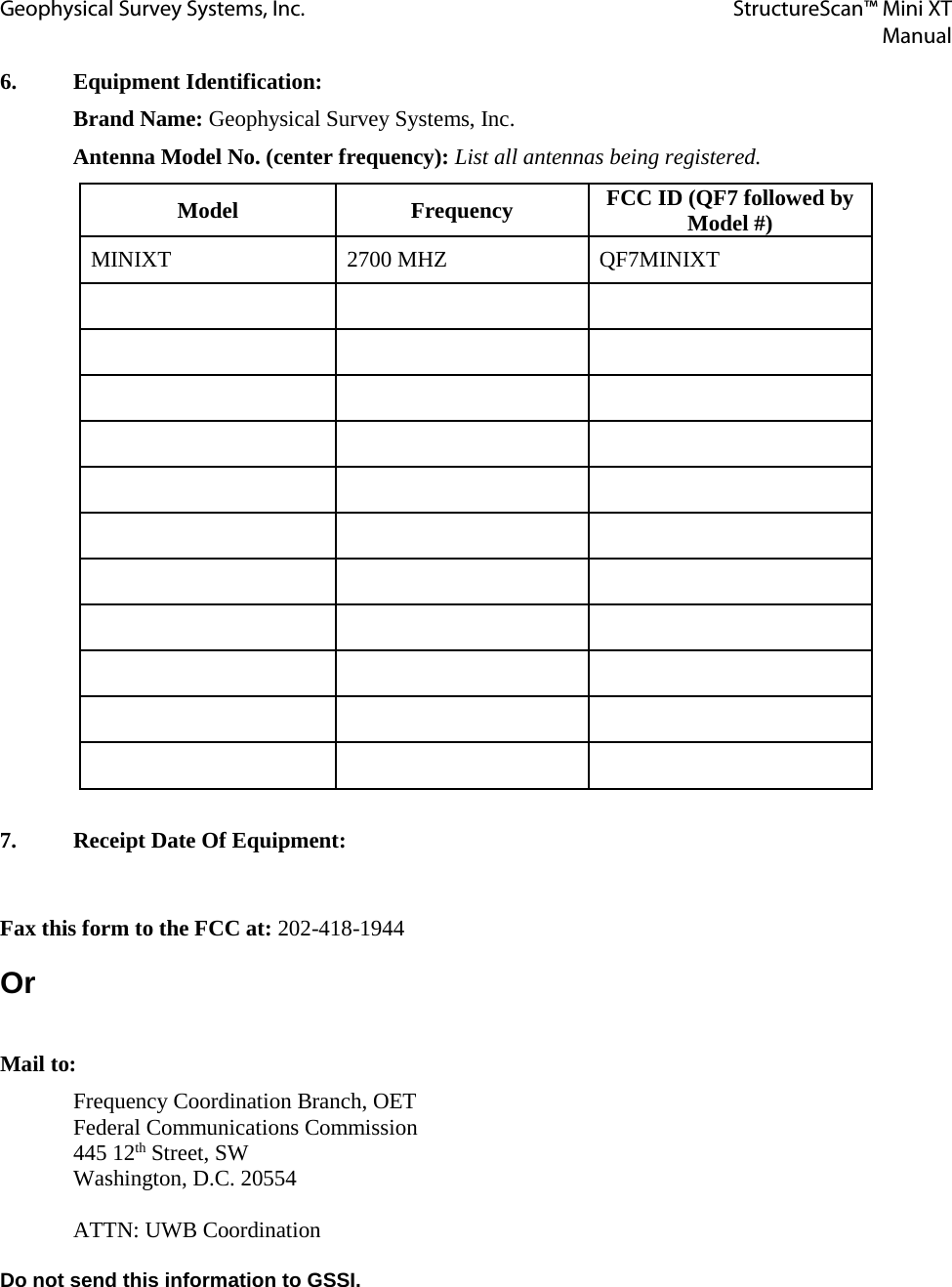
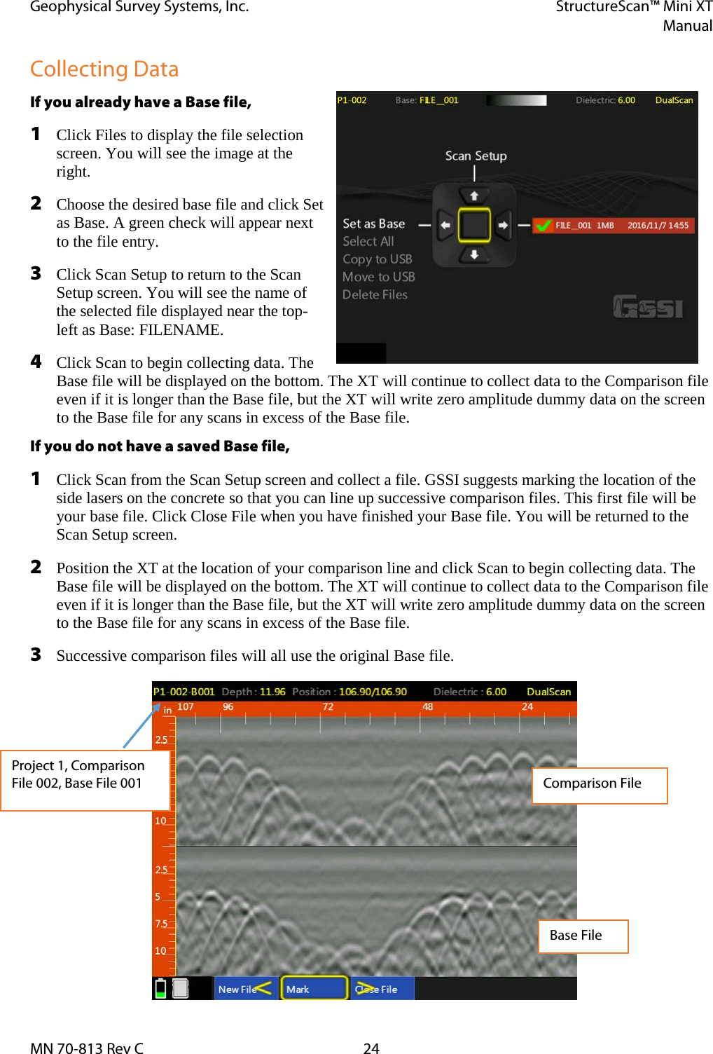
![Geophysical Survey Systems, Inc. StructureScan™ Mini XT Manual For U.S. Customers Ground Penetrating Radar Coordination Notice And Equipment Registration Note: This form is only for Domestic United States users. The Federal Communications Commission (FCC) requires that all users of GPR who purchased antennas after July 15th, 2002 register their equipment and areas of operation. It is required that you fill out this form and fax or mail to the FCC. Failure to do this is a violation of Federal law. 1. Date: 2. Company name: 3. Address: 4. Contact Information [contact name and phone number]: 5. Area Of Operation [state(s)]: ---Continued on next page.](https://usermanual.wiki/Geophysical-Survey-Systems/PALMXT/User-Guide-3301743-Page-7.png)