Geophysical Survey Systems TERRAVISION User Manual QF7TERRAVISION
Geophysical Survey Systems, Inc. QF7TERRAVISION
Transmitter user manual

Geophysical Survey Systems, Inc. Model 5106 Antenna
System Settings and User Notes
Manual MN71-082 Rev - 1
User Manual
We Provide Complete Survey Solutions
Geophysical Survey Systems, Inc.
13 Klein Drive, P.O. Box 97
North Salem, NH 03073-0097
Phone: (603) 893-1109 / FAX: (603) 889-3984
www.geophysical.com
sales@geophysical.com

Manual MN71-082 Rev - 2
Limited Warranty, Limitations Of Liability And Restrictions
Geophysical Survey Systems, Inc. hereinafter referred to as GSSI, warrants that, for a period of 12 months from the
delivery date to the original purchaser, GSSI's products will be free from defects in materials and workmanship.
EXCEPT FOR THE FOREGOING LIMITED WARRANTY, GSSI DISCLAIMS ALL WARRANTIES, EXPRESS
OR IMPLIED, INCLUDING ANY WARRANTY OF MERCHANTABILITY OR FITNESS FOR A
PARTICULAR PURPOSE. GSSI's obligation is limited to repairing or replacing parts or equipment which are
returned to GSSI, transportation and insurance pre-paid, without alteration or further damage, and which in GSSI's
judgment, were defective or became defective during normal use.
GSSI ASSUMES NO LIABILITY FOR ANY DIRECT, INDIRECT, SPECIAL, INCIDENTAL OR
CONSEQUENTIAL DAMAGES OR INJURIES CAUSED BY PROPER OR IMPROPER OPERATION OF ITS
EQUIPMENT OR SOFTWARE, WHETHER OR NOT DEFECTIVE.
Before returning any equipment to GSSI, a Return Material Authorization (RMA) number must be obtained. Please
call the GSSI Customer Service Manager who will assign an RMA number. Be sure to have the serial number of the
unit available.
GSSI does not convey any license under its patent or other intellectual property rights or the rights of others.
Note: Information in this manual is subject to change without notice. Please consult the
manual updates supplied with your system and contact GSSI with any additional
questions.
Copyright© 2001, 2002 Geophysical Survey Systems, Inc.
All rights reserved, including the right of reproduction in whole or in part in any form
Published by Geophysical Survey Systems, Inc.
13 Klein Drive
North Salem, New Hampshire 03073-0097
Printed in the United States
GSSI and SIR are registered trademarks of
Geophysical Survey Systems, Inc.
Manual MN71-082 Rev - 3
This device complies with part 15 of the FCC Rules:
Operation is subject to the following conditions:
1. This device may not cause harmful interference, and
2. This device must accept any interference received, Including
interference that may cause undesired operation
Warning: Changes or modifications to this unit not expressly approved by the party responsible for
compliance could void the user’s authority to operate the equipment.
Operation of this device is restricted to law enforcement, fire and rescue officials,
scientific research institutes, commercial mining companies, and construction
companies. Operation by any other party is a violation of 47 U.S.C. § 301 and could
subject the operator to serious legal penalties.
Coordination Requirements.
(a) UWB imaging systems require coordination through the FCC before the equipment may
be used. The operator shall comply with any constraints on equipment usage resulting from this
coordination.
(b) The users of UWB imaging devices shall supply detailed operational areas to the FCC
Office of Engineering and Technology who shall coordinate this information with the Federal
Government through the National Telecommunications and Information Administration. The
information provided by the UWB operator shall include the name, address and other pertinent
contact information of the user, the desired geographical area of operation, and the FCC ID number
and other nomenclature of the UWB device. This material shall be submitted to the following
address:
Frequency Coordination Branch., OET
Federal Communications Commission
445 12th Street, SW
Washington, D.C. 20554
ATTN: UWB Coordination
(d) Users of authorized, coordinated UWB systems may transfer them to other qualified
users and to different locations upon coordination of change of ownership or location to the FCC and
coordination with existing authorized operations.
(e) The NTIA/FCC coordination report shall include any needed constraints that apply to
day-to-day operations. Such constraints could specify prohibited areas of operations or areas
located near authorized radio stations for which additional coordination is required before operation
of the UWB equipment. If additional local coordination is required, a local coordination contact will be
provided.
(f) The coordination of routine UWB operations shall not take longer than 15 business days
from the receipt of the coordination request by NTIA. Special temporary operations may be handled
with an expedited turn-around time when circumstances warrant. The operation of UWB systems in
emergency situations involving the safety of life or property may occur without coordination provided
a notification procedure, similar to that contained in CFR47 Section 2.405(a)-(e), is followed by the
UWB equipment user.
Manual MN71-082 Rev - 4
Table of Contents
Table of Contents.......................................................................................................................4
Chapter 1: Introduction ............................................................................................................5
Overview of this Manual..................................................................................................5
Chapter 2: Hardware Configuration......................................................................................7
Hardware Components........................................................................................................... 7
Cable Connections .................................................................................................................. 8
Chapter 3: Data acquisition procedure................................................................................9
Data Collection......................................................................................................................... 9
Acquisition Details .................................................................................................................12
Positioning.....................................................................................................................12
Depth Measurement....................................................................................................15
Chapter 4: Post-Processing Procedure.............................................................................17
Transferring data to RADAN................................................................................................17
Running RADAN....................................................................................................................17
Appendix B: Troubleshooting Problems...........................................................................18
Manual MN71-082 Rev - 5
Chapter 1: Introduction
Terravision II is GSSI’s first truly One-Pass 3D system. This affords faster and more accurate
data collection and target identification than has ever been available before. The design goal has
been to assist you in detecting the location, depth and angle of pipes --- automatically.
The Terravision II let’s you collect a six-foot wide ribbon of data at a range of speeds and
resolutions that adapt to your application. It is designed to collect 1200 feet of data at three to
four miles per hour. This will deliver the full resolution of one scan per inch. At this resolution,
even rebar mesh is detectable. Going faster is no problem. As your speed increases, the
Terravision II automatically drops resolution and correctly smoothes the data to accommodate. At
the far extreme for example, if you wish to map soil layering, roadbed or geologic structure,
speeds up to fifteen mph will still provide smoothed yet accurate results thanks of its built-in
positioning system. The internal survey wheel will track your position, while the fixed relative
position of the 14 internal antennas guarantees a six-foot swath of correctly spaced 3D data.
At typical speeds for locating pipes (3 to 5 mph) you can collect over a 1500-foot line in under
five minutes. Anyone with experience collecting 3D data will recognize not only what a
generational advance in technology this represents but also what a huge dataset you have just
collected! With this is mind, the second important technology advance with this system lies in the
way it helps you analyze your data.
Once the dataset is collected, it is transferred to our RADAN processing software for analysis.
This can be done immediately after data collection, without leaving your ATV. Our new Auto
Target Locator takes the 3D dataset and looks for hyperbolic patterns in all 14 transects. While
some of these targets might be individual rocks or buried trash, pipes should get detected in each
of the 14 transects. The 14 targets will be found to be linear and then automatically highlighted in
the data. The result is a simple means of searching through an enormous amount of 3D data very
quickly.
The results of your analysis are presented, edited and saved in an easy to use 3D interface that can
be outputted to a CAD file. Whether you want to locate pipes to within a few inches, or map soil
stratigraphy in 3D, Terravision II offers a simple and efficient means of getting answers fast. This
manual is written to help you get the most out of your new system, to highlight its strengths and
understand its limitations. Please read it through carefully to avoid confusion.
Overview of this Manual
Chapter 2 – Details the components and requirements of the hardware and setup
Chapter 3 – Steps through the procedure for acquiring data.
Chapter 4 – Explains what needs to be done to interpret your data.
Appendix A – FAQ.
Manual MN71-082 Rev - 6
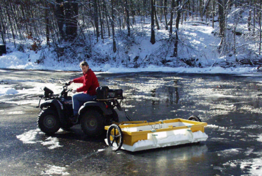
Figure 1: One possible Terravision II configuration.
Manual MN71-082 Rev - 7
Chapter 2: Hardware Configuration
Let’s begin with an overview of where the pieces go and how to hook them together.
Hardware Components
The main component is the two-wheeled cart. It contains the frame and hitch (in gold), the antenna sled
(in white) and a right and left antenna array pair (in white). The Right antenna is the Master antenna and
goes on the right side as you face forward The Left antenna is the Slave antenna and goes on the left side as
you face forward. The cart itself can be hooked up in either direction; just make sure that the Right and Left
antennas are oriented properly with the direction of travel.
The hitch is connected to the ATV with a ball joint. Four handle clips on the frame allow the antenna to be
pulled up off the ground. When the antenna is “up,” an extra rail on top of the frame can be pinned to the
hitch (as shown in Figure 1) to allow the antenna to be moved without dragging it on the ground.
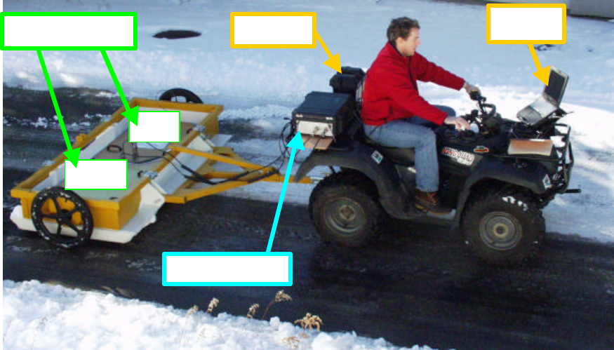
On the back of the ATV, secure the Battery and the Controller Box. The Laptop sits in its own frame that
clamps onto the front frame on the ATV. These are the only components; now let’s look at how to hook
them together.
Figure 2: Hardware layout.
Controller Box
Right
Left
Antenna Arrays
Battery
Laptop
Manual MN71-082 Rev - 8
Cable Connections
Considering its complexity, it may be surprising that Terravision II has only a handful of connections.
1) The survey wheel has a cable coming out of the frame that gets hooked up to either antenna array.
2) A foot-long cable connects the two antenna arrays together.
3) Two identical cables go from the Antenna Array to the Controller Box.
Make sure to get the male and female ends right.
It doesn’t matter which connection you use on the Controller Box; they are identical.
4) An Ethernet cable connects the Controller Box to the Laptop.
5) Battery power goes both to the Controller Box and to the AC/DC converter hidden under the
Laptop mounting frame.
That’s it.
Hooks and clips are located in logical places. Check your ATV for the best way to secure the cables. The
connections that go to the laptop can usually be hidden safely under the seat.
A key on the side of the Controller Box is used to switch power on. It powers everything but the laptop.
Manual MN71-082 Rev - 9
Chapter 3: Data acquisition procedure
The data acquisition procedure is so simple that it is easy to make basic mistakes during data collection.
But if everything is set up right, it is a four click process. Let’s go through this first, and then get into the
sometimes tricky details.
Data Collection
Step 1: Turn on the key to the Controller Box.
Since the two computers inside the Controller box need time to boot up,
wait about 45 seconds after it is turned on before Step 3.
Step 2: Turn on the Laptop (slide switch on the back right).
If you get asked, User = Administrator Password = Administrator.
On the Controller box, the Green and Amber lights will start flashing.
Then just the green power light stays on.
Step 3: Double click on the TERRA 2 icon in the middle of the Windows 2000 desktop.
The laptop then checks if the Controller box is booted and running.
After maybe 10 seconds, the application logo should appear. Be patient!
Double clicking again does nothing
If the Controller Box is not ready, you will get an error message. Say ok and try again.
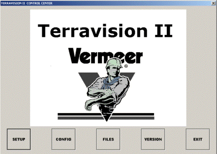
Figure 3: Main Screen.
Now you are ready to run the application.
Step 4: Hitting SETUP shows the next screen (Figure 4)
If you don’t see any data in the O-Scope box on the right, then the application was started before
the Controller Box was ready. Quit the application and try again.
Manual MN71-082 Rev - 10
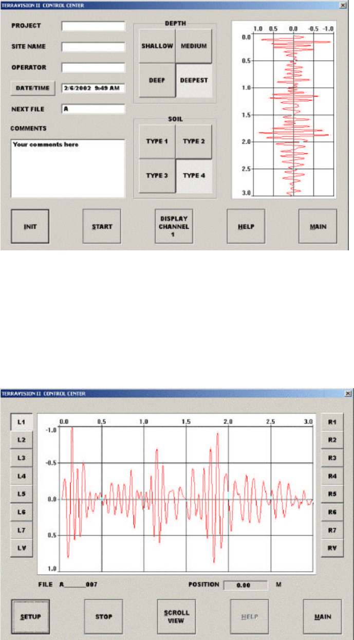
Figure 4: SETUP Screen.
Step 5: Hit INIT to initialize the gains on all fourteen antennas.
When beeping stops, and when the O-Scope pattern on the right starts moving again, it is finished.
Step 6: Hit START.
The next O-Scope screen will appear blank. It is waiting for you to move forward.
It will not show data until you have moved forward about half the length of the antenna array
(Figure 5).
Figure 5: START Screen.
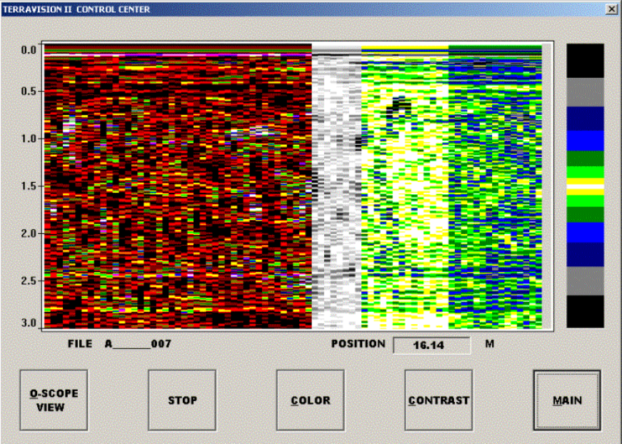
Manual MN71-082 Rev - 11
Figure 6: Scroll View Window has flexible display parameters.
The Scroll View (Figure 6) lets you preview the output during collection. Only every 16th scan is
displayed (to not waste processing time) but it is enough to see general trends and pipes
in the data.
Step 7: Hit STOP when you are finished the survey.
Start the next survey by hitting START again (etc.).
The filename increments automatically.
Manual MN71-082 Rev - 12
Acquisition Details
Positioning
A good survey requires accurate and repeatable positioning. There are three ways we try to help.
1) Mark your starting position in a way you can refer to, either with tape of spray-paint of a stick
etc. The starting line on our antenna is the forward-most line marked on top of the antenna
arrays. On this line, the position of the right-most antenna is the defined as (0,0) (Figure 7). It
is best to plan your survey with this in mind, especially if you want to make multiple passes
and tile them all together in our Super3D Mode.
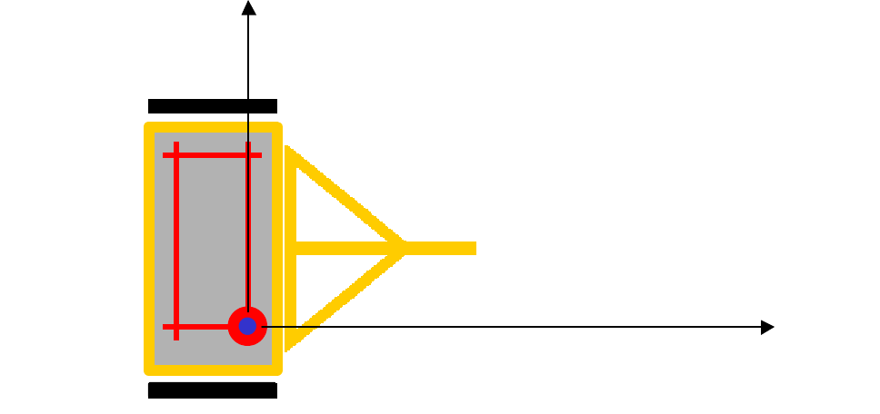
Figure 7: Data Orientation relative to cart.
Backing up (other than being difficult with a trailed cart) is not a problem. During data
collection, the survey wheel will remember its last forward progress and continue once you
return to this point.
However, making turns must be done with full knowledge that the survey wheel is only on
one side of the cart. Therefore, when measuring a distance to a pipe, you MUST measure
along the track of the survey wheel, not along the center of the cart. This also means that our
displayed distance of a survey will be longer for a right turn and shorter for a left turn. If this
is fatal problem, our standard survey wheel can always be attached and dragged directly
behind the antenna and connected to the units.
2) Make sure your Survey Wheel is calibrated properly. This procedure, once done carefully,
should not need to be repeated (unless tire pressure changes, or you decide to switch units
Metric/English).
X
Y
R
L
Manual MN71-082 Rev - 13
I
n
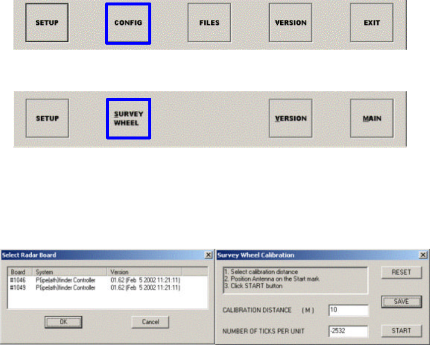
The first menu (Main) hit CONFIG. In the next screen hit SURVEY WHEEL.
This pops up a dialog box with the internal numbers of the Right (Even) and Left (Odd) antenna
arrays (Figure 8). We calibrate only one, and then copy the result to the other, making sure they
are exactly the same. Select the even one and hit OK. The next dialog box gives instructions on
how to calibrate. Hit START. Move forward the “Calibration Distance.” Hit Stop. The results, the
number of Ticks Per Un it, are the number to copy to the odd antenna. Hitting save quits.
Figure 8: Survey Wheel Calibration Dialogs
Hit the SURVEY WHEEL button a second time. This time select the odd number and hit ok.
Don’t repeat the calibration. Instead just Paste (or copy in) the TICKS PER UNIT number you got
from your calibration of the even side. Hit Save. Now they are both correct. Calibration is done.
Typical values for TICKS PER UNIT are Meters = 2533, Feet = 775 (+ or - depending on which
direction the cart is pointed)
Manual MN71-082 Rev - 14
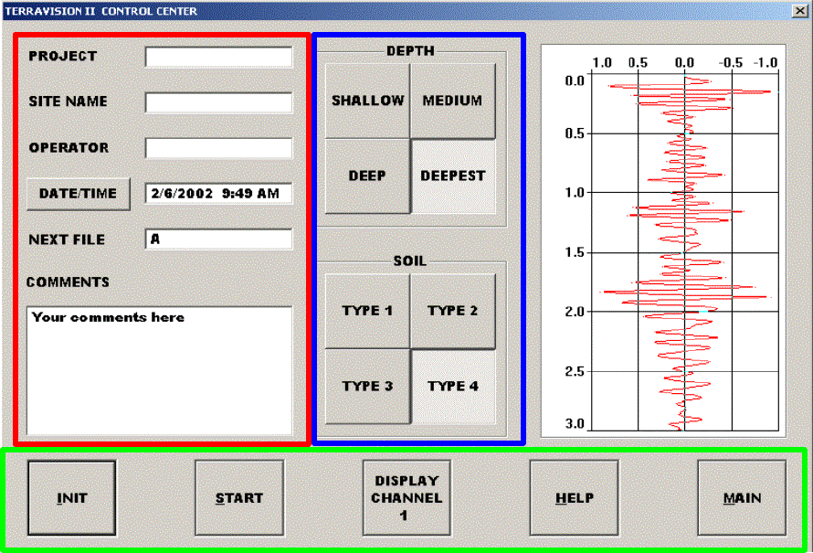
3) Keep good notes, either in our software or in a notebook.
The SETUP menu offers a place in which to write PROJECT Notes (Figure 9). These notes
go with the created 3D File and can be viewed in the Header in RADAN during post-
processing. If you do a subsequent survey the filename increments automatically, but the
other information remains the same unless you change it.
Figure 9: The SETUP screen has a section for taking notes
Manual MN71-082 Rev - 15
Depth Measurement
Before running a successful survey, you need to know two things:
1) How far down do you want to see.
2) What type of soil you are over. (i.e. what dielectric value should be set.)
If you don’t know 2), we have tricks to help get you this information.
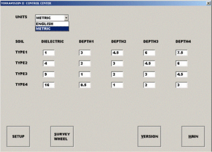
This is the information used to fill the CONFIG table (Figure 10).
Figure 10: Configuration Page
A typical matrix is shown above. However, if you happen to know the exact soil type, then you can enter
the exact dielectric value in. You can also get the soil dielectric by surveying over a pipe and running the
auto-target software (more on this later).
Manual MN71-082 Rev - 16
Manual MN71-082 Rev - 17
Chapter 4: Post-Processing Procedure
Transferring data to RADAN
Once the data is collected remember that it still resides only in the memory inside the antennas, not yet in
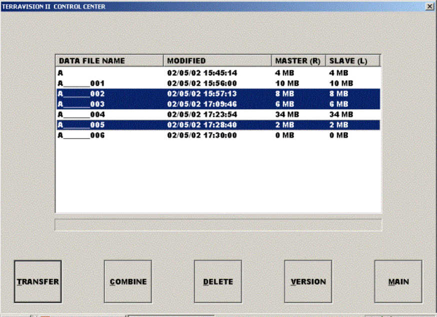
the laptop. To transfer the data so you can look at it in RADAN, return to the main menu and hit FILES.
The TII Control Center pops up which lets you transfer files to your laptop. Highlight the file(s) and hit
COMBINE. This sorts the data into a standard 3D RADAN.DZT file
Figure 11: File transfer screen
You can now close the TII application and run our standard RADAN package for looking at the data.
Running RADAN
The data can now be opened in RADAN for viewing. To make it a 3D file
select PROCESS -> SORTING -. Sort 3D Data. This changes the file so that it can be viewed as a 3D file
in 3D QuickDraw. Please refer to that manual for further details.
Manual MN71-082 Rev - 18
Appendix B: Troubleshooting Problems
Problem: Some lights don’t turn on, or don’t shut off
Solution: When unusual behavior appears there are usually only two culprits
1) Occasionally the antennas get confused about what state they are in. Try closing the TII program
on the laptop, then shutting off the power to the CONTROL BOX. Turn it back on and then re-run
the T2 application. Eveything should now behave.
2) If this doesn’t fix the problem, then the problem has always been that the battery power has fallen
below useable levels. Swap out with a newly charged battery and try again.
3) If the problem persists, call us.
Problem: The distance is not correct.
Solution: Recalibrate the survey wheel. Make sure that the same number is loaded in both antennas.
Problem: We move and nothing appears on the screen.
Solution:
1) Check that the cables are screwed in correctly.
2) Make sure you see lights blinking on the Ethernet card inserted in the laptop. (else reboot)
3) Recalibrate the survey wheel. Make sure that the same number is loaded in both antennas.
4) The Survey encoder does not operate below 10 F.
Manual MN71-082 Rev - 19
Problem: RADAN-NT crashes while trying to write a file:
Solution: There are two possibilities:
1. Check to make sure there is enough disk space on the disk containing the Output file path. Allow for at
least twice the combined space taken up by the input file (*.dzt) and the *.ind file.
2. Check to make sure the default output path exists. The output path is specified in the Customize menu
item. See Appendix C for details on locating and setting the default output path.