Geophysical Technology NRU1C9G2Y1 NRU 1C User Manual Field Equipment

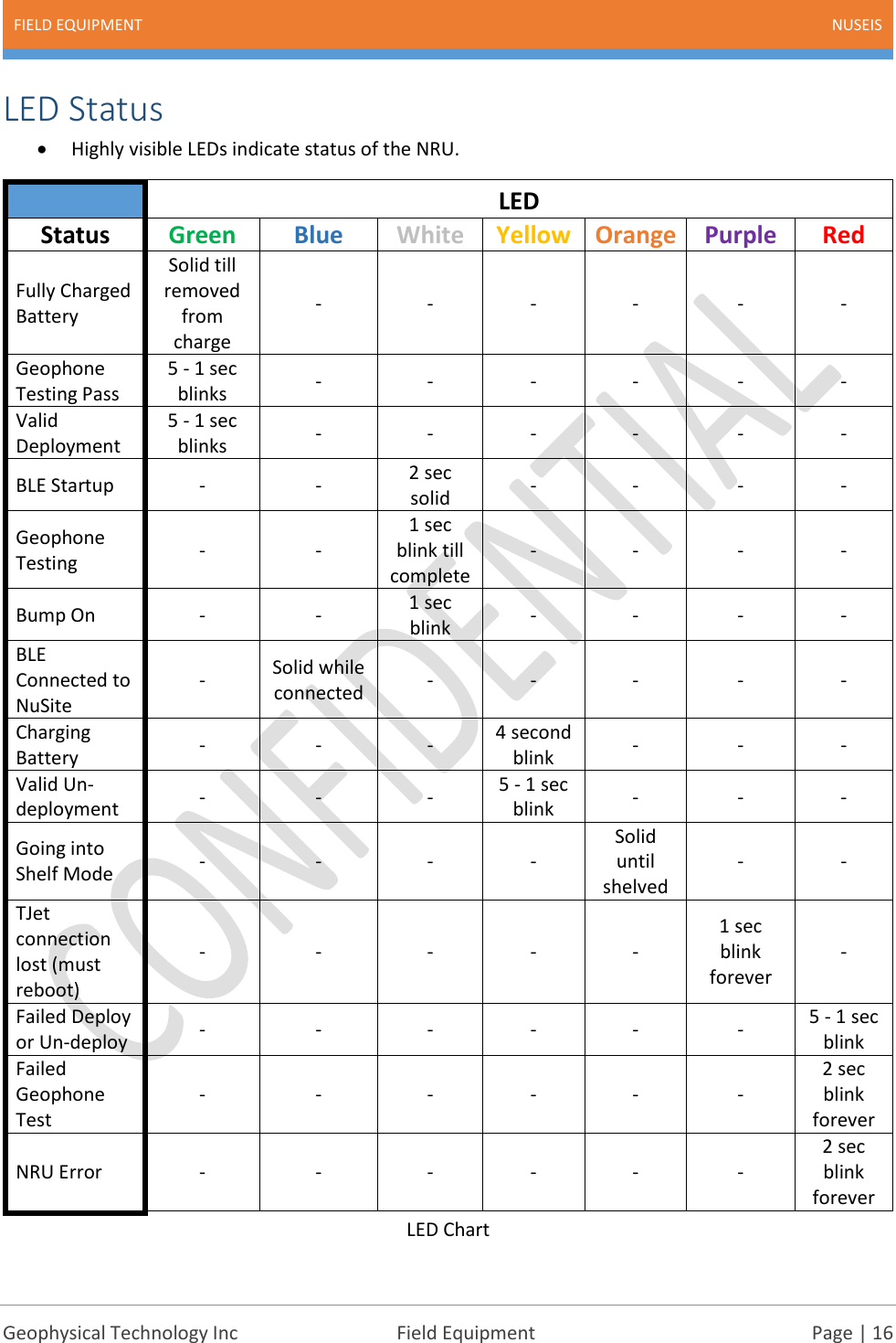
Geophysical Technology Inc. NRU 1C Field Equipment

Users Manual Rev 1_3b

  NuSeis System GEOPHYSICAL TECHNOLOGY INC | WWW.GEOPHYSICALTECHNOLGY.COM Field Equipment USER MANUAL
FIELD EQUIPMENT NUSEIS    Geophysical Technology Inc  Field Equipment  Page | 1  Document Identifier: Field Equipment   This document describes the NuSeis Field Equipment. This manual is believed to be correct and accurate, however Geophysical Technology Inc reserves the right to make changes to products, software or specifications without notice at any time to improve performance, reliability, and functionality. Information contained in this document may not be modified or altered in any form without the expressed written consent of Geophysical Technology Inc.  Revision Description Author Checked By Approved By Date 1.0 First Draft DR   12-May-17  1.1 Adjusted references DR   13-Jun-17 1.2 Edits and added features DR   24-Aug-17 1.3 FCC Statement added DR   29-Sept-17 1.3b Edits, name change for DMP DR   26-Oct-17
FIELD EQUIPMENT NUSEIS    Geophysical Technology Inc  Field Equipment  Page | 2  Contents Chapter 1 Introduction ................................................................................................................................. 4 Overview ................................................................................................................................................... 5 Handling .................................................................................................................................................... 6 Chapter 2 NRU-1C ......................................................................................................................................... 7 User Manual Statement – FCC .................................................................................................................. 8 NRU-1C Specifications ............................................................................................................................... 9 NRU-1C Block Diagram ............................................................................................................................ 10 NRU-1C Description ................................................................................................................................ 11 Physical................................................................................................................................................ 11 Power .................................................................................................................................................. 12 Geophone Sensor ................................................................................................................................ 13 Hardware ............................................................................................................................................ 15 LED Status ........................................................................................................................................... 16 NRU-1C Preparation ................................................................................................................................ 17 Cleaning ............................................................................................................................................... 17 Charging .............................................................................................................................................. 17 Shelf Mode .......................................................................................................................................... 17 States................................................................................................................................................... 17 Programming ...................................................................................................................................... 18 Bumping .............................................................................................................................................. 18 NRU-1C Field Use .................................................................................................................................... 18 Laying Out ........................................................................................................................................... 18 Picking Up ............................................................................................................................................ 20 Downloading ....................................................................................................................................... 20 Chapter 3 NRU-1C-KCK................................................................................................................................ 21 NRU-1C-KCK Description ......................................................................................................................... 22 Chapter 4 Data Management Panel............................................................................................................ 23 Data Management Panel Overview ........................................................................................................ 24 Data Management Panel Use ................................................................................................................. 24 Chapter 5 Charging Panel............................................................................................................................ 26 Charging Panel Overview ........................................................................................................................ 27
FIELD EQUIPMENT NUSEIS    Geophysical Technology Inc  Field Equipment  Page | 3  Charging Panel Use ................................................................................................................................. 27 Chapter 6 Portable Case – Charging ........................................................................................................... 29 Portable Case - Charging Description ..................................................................................................... 30 Use of the Portable Case - Charging ....................................................................................................... 30 Chapter 7 Portable Case – Data Management & Charging......................................................................... 32 Portable Case – Data Management & Charging Description .................................................................. 33 Use of the Portable Case – Data Management & Charging .................................................................... 34 Chapter 8 Manual Deployment/Extraction Tools ....................................................................................... 36 Deployment Tool..................................................................................................................................... 37 Extraction Tool ........................................................................................................................................ 40 Chapter 9 Automated Deployment System ................................................................................................ 42 Automated Deployment System V3 ....................................................................................................... 43 ADS V3 Specifications.............................................................................................................................. 44
FIELD EQUIPMENT NUSEIS    Geophysical Technology Inc  Field Equipment  Page | 4             Chapter 1 Introduction
FIELD EQUIPMENT NUSEIS    Geophysical Technology Inc  Field Equipment  Page | 5  Overview  Figure 1 • The most important part of the NuSeis Ecosystem is the field equipment. • The NRU-1C is deployed in the field to record seismic data. • The data is recorded in proprietary format on a uSD card. The data is extracted and output in SegY format by NuScribe. • Deployment of the NRU in the field can be done with several different methods. • Manual deployment and extraction tools can be used for most applications. • The ADS V3 automatic deployment system allows for accurate quick automated deployment. • NRU-1C-KCK units have an external connector that allows for recording with external geophone strings, or recording of auxiliary channels from the recorder encoder.
FIELD EQUIPMENT NUSEIS    Geophysical Technology Inc  Field Equipment  Page | 6  Handling • While the construction of the NuSeis field equipment is extremely rugged and robust, some of the equipment still contains electronic circuitry that could possibly be damaged by heavy physical shock and abuse. • Handling of all NuSeis equipment should be done in accordance with precautions and instructions described in the NuSeis Manuals.  • NRUs should be handled with care. Avoid dropping or throwing the devices so as to cause a heavy shock to be translated into the internal electronics. Use the prescribed transportation and handling methods, never transport the NRUs loose in a vehicle.  PLEASE NOTE:   Any misuse or mishandling of any NuSeis equipment will void the manufacturer warranty and any required repairs will be at the buyer’s cost.    Unauthorized attempts to open or repair NuSeis warranted equipment will void the warranty and any required repairs will be at the buyer’s cost.
FIELD EQUIPMENT NUSEIS    Geophysical Technology Inc  Field Equipment  Page | 7             Chapter 2 NRU-1C
FIELD EQUIPMENT NUSEIS    Geophysical Technology Inc  Field Equipment  Page | 8  User Manual Statement – FCC  This device complies with Part 15 of the FCC Rules. Operation is subject to the following two conditions: 1. This device may not cause harmful interference, and 2. This device must accept any interference received, including interference that may cause undesired operation. Changes or modifications not expressly approved by the party responsible for compliance could void the user’s authority to operate the equipment. This equipment has been tested and found to comply with the limits for a Class B digital device, pursuant to Part 15 of the FCC Rules. These limits are designed to provide reasonable protection against harmful interference in a residential installation. This equipment generates, uses and can radiate radio frequency energy and, if not installed and used in accordance with the instructions, may cause harmful interference to radio communications. However, there is no guarantee that interference will not occur in a particular installation. If this equipment does cause harmful interference to radio or television reception, which can be determined by turning the equipment off and on, the user is encouraged to try to correct the interference by one of the following measures: • Reorient or relocate the receiving antenna. • Increase the separation between the equipment and receiver. • Connect the equipment into an outlet on a circuit different from that to which the receiver is connected. • Consult the dealer or an experienced radio/TV technician for help. To comply with FCC RF exposure limits for general population / uncontrolled exposure, the antenna(s) used for this transmitter must be installed to provide a separation distance of at least 20 cm from all persons and must not be co-located or operating in conjunction with any other antenna or transmitter.
FIELD EQUIPMENT NUSEIS    Geophysical Technology Inc  Field Equipment  Page | 9  NRU-1C Specifications    Acquisition Channel @2ms sample interval, 25°C, 31.25Hz  Maximum input signal: 1768mVrms @0dB Total Harmonic Distortion: 0.0001% @31.25Hz Instantaneous Dynamic Range @ 12dB gain:  123dB @ 2ms 121dB @ 1ms 119dB @ 0.5ms Equivalent Input Noise:  1500nV @ 0dB 400nV @ 12dB 160nV @ 24dB Gain Accuracy: 0.25% unit to unit Input Impedance: 20kohm Timing Accuracy:  +/- 12.5usec GPS Time Standard: Better than 500ppb  Sensor Test Resistance, Impedance, Noise  Sensor Internal Single Geophone: 10Hz +/-3.5% 85.8V/m/s +/-3.5% Other geophones available on request  Internal Test Impulse Response, Noise, Total Harmonic Distortion  Memory 8GB standard (expandable to 16, 32, or 64GB) ~55 days @ 2ms ~27 days @ 1ms Seismic Data Channel 1 Component  ADC Resolution  24-Bit Delta Sigma Preamplifier Gain Programmable 0dB to 42dB in 6dB steps  Anti-alias Filter 206.5Hz @ 2ms      413Hz @ 1ms Linear Phase and Minimum Phase  Operating Temperature Range -40°C to +60°C  Weight 0.862 kg, 1.9 lbs.  Dimensions Max 50.5mm tube  299 mm long  standard M60 hex Max 1.988” tube 11.77” long Standard M60 hex  Battery Type: 10ah Li-Ion Charging Time: ~6 hours from cutoff to 100% Charging Temperature Range: 0°C to 45°C Cycle Life: >500 cycles to 80%  Battery Longevity ~360 Hours 12 hours/day: ~30 days 24 hours/day: ~15 days   Communication Wireless: Bluetooth (BLE low power) Transfer Jet Proximity
FIELD EQUIPMENT NUSEIS    Geophysical Technology Inc  Field Equipment  Page | 10  NRU-1C Block Diagram   Figure 2
FIELD EQUIPMENT NUSEIS    Geophysical Technology Inc  Field Equipment  Page | 11  NRU-1C Description   Physical • The case of the NRU-1C consists of 4 parts. o Bottom Assembly – a tapered high strength tube that encases the NRU clamshell assembly and geophone element. The shape and design enhance the NuSeis EarthGrip technology. o Cap Assembly – high strength clear plastic allows for full view of the high visibility LEDs in the NRU. Incorporates an Ultramid insert that has 2 stainless steel MIMs for battery charging and connection to an external battery. o Bottom Clamp – stainless steel threaded ring used to secure the bottom assembly. o Top Clamp – stainless steel M60 hex nut used to secure the top assembly.  Figure 3 Top Clamp Cap Assembly  Bottom Assembly  Bottom Clamp
FIELD EQUIPMENT NUSEIS    Geophysical Technology Inc  Field Equipment  Page | 12  Power • Internal battery – 10Ah Li-Ion • The battery is protected by the clamshell assembly and a rubber compression square ring for shock absorption. • Charger is built into the NRU. This allows charging by simply applying a DC voltage to the top assembly MIMs connectors. 12 to 15vdc can be used for charging purposes, 12vdc is optimal.  Figure 4  • An external battery may be connected to the NRU to either charge the internal battery in the field, or to serve as an extra power source depending on the voltage of the battery used. 5 to 9vdc    Figure 5
FIELD EQUIPMENT NUSEIS    Geophysical Technology Inc  Field Equipment  Page | 13  Geophone Sensor • The NRU-1C has an internal single geophone sensor embedded in the bottom case.  • The location of the geophone and the design of the case incorporates the EarthGrip technology. • The normally supplied geophone is a Sunfull PS-10R. Other sensors are available upon request.  Figure 6
FIELD EQUIPMENT NUSEIS    Geophysical Technology Inc  Field Equipment  Page | 14   Figure 7   Figure 8 • There is no shunt resistor on the Sunfull geophone • A rubber grommet is used on top of the geophone for compression of the geophone into the bottom case of the NRU.
FIELD EQUIPMENT NUSEIS    Geophysical Technology Inc  Field Equipment  Page | 15  • Resistance, impedance, noise and distortion tests ensure the quality of the geophone sensor. LED indicators and NuSite tools help QC the test results. Hardware • The NRU electronics are protected by a 2-part clamshell, as well as the high strength design of the case assembly. • See the electronic block diagram on page 7. • There are 4 boards. o Antenna Board ▪ BLE Bluetooth device and antenna. Used for status broadcasting and NuSite communications ▪ Transfer Jet device and antenna. For data offloading, parameter and firmware programming ▪ GPS module and connection to the GPS antenna. ▪ Serves as motherboard for digital and analog board interconnection o Digital Board ▪ LED status indicators ▪ Battery charging circuit, including the connection to the Cap Assembly MIMs ▪ uSD card. Stores the seismic data in proprietary format. Easily swappable ▪ Processor o Analog Board ▪ LED status indicators ▪ Connector for the geophone element ▪ Analog switching for the geophone input circuitry ▪ A to D converter ▪ High precision clock circuitry o GPS Antenna Board     Clamshell Figure 9
FIELD EQUIPMENT NUSEIS    Geophysical Technology Inc  Field Equipment  Page | 16  LED Status • Highly visible LEDs indicate status of the NRU.   LED Status Green Blue White Yellow Orange Purple Red Fully Charged Battery Solid till removed from charge - - - - - - Geophone Testing Pass 5 - 1 sec blinks - - - - - - Valid Deployment 5 - 1 sec blinks - - - - - - BLE Startup - - 2 sec solid - - - - Geophone Testing  - - 1 sec blink till complete - - - - Bump On - - 1 sec blink - - - - BLE Connected to NuSite - Solid while connected - - - - - Charging Battery - - - 4 second blink - - - Valid Un-deployment - - - 5 - 1 sec blink - - - Going into Shelf Mode - - - - Solid until shelved - - TJet connection lost (must reboot) - - - - - 1 sec blink forever - Failed Deploy or Un-deploy - - - - - - 5 - 1 sec blink Failed Geophone Test - - - - - - 2 sec blink forever NRU Error - - - - - - 2 sec blink forever LED Chart
FIELD EQUIPMENT NUSEIS    Geophysical Technology Inc  Field Equipment  Page | 17  NRU-1C Preparation Cleaning • Make sure that the top caps of the NRUs are clean and free of mud or wet material, or a large amount of dust. • Dust can be removed using a dry brush. • Mud can be washed off with clean water and a brush. Do not pressure wash the NRUs. • A very light soap/water mixture can be used to wash the NRUs, but must be rinsed off with clear water. ➢ Never use CRC or any other type of aerosol cleaning agent to clean the case of the NRU. Use of an aerosol cleaner or chemical cleaner could result in damage to the case. • Let the NRUs dry off prior to charging or downloading. Charging • See the sections for use of the Charging Panel page 25, and Portable Charging Case page 28. • Ensure that the NRUs are clean as stated in the section above. • The NRU LEDs will blink yellow while charging • The NRU should charge until the LEDs show solid green indicating full charge. ➢ If a NRU shows yellow blinking LEDs for over 12 hours, or never blinks yellow when charge current is applied. The NRU should be removed from charge and checked for defects.  Shelf Mode • Shelf Mode – powered off. This can be done during data offload, parameter programming, or with NuSite in the field. See NuSite manual page 50, NuScribe manual page 46 o To take the NRU out of shelf mode, it will either need to be “bumped” or placed on charge. States • Deployed – in this state the NRU is active. The NRU is recording seismic data, GPS receiver is on at intervals, system clock is locked, and status is being broadcast. This state can be set during offload, parameter programming or by NuSite in the field. See NuSite manual page 48, NuScribe manual page 61  • Un-deployed – in this state the NRU is partially active. The NRU is not recording, the GPS receiver is in a low power mode, the system clock is not locked, status is being broadcast. This state can be set during offload, parameter programming or by NuSite in the field. See NuSite manual page 49, NuScribe manual page 61
FIELD EQUIPMENT NUSEIS    Geophysical Technology Inc  Field Equipment  Page | 18  Programming • See the NuScribe manual page 62. • Parameters for the current project will be set during programming, as well as checking firmware levels and correcting them if they are not current. • Setting the mode and state of the NRU at the end of programming or downloading is an operational decision.  o Many variables can come into play when deciding which mode to set the NRU to. For example, storage time after programming, recording time required, days in the field, roll requirements, etc. o The NRU should be placed in Shelf mode if it is to be stored for a long period or if every minute of battery life is required, so that the NRU is only bumped on right before recording is required. o If the NRU is going to be placed in the field immediately after programming or offloading, it should be put in a Deployed state.  o If there will be a small period before the NRU is placed in the field it should be put in an Un-deployed state to save battery life. Bumping • When a NRU has been placed in Shelf mode, one way to turn it back on is bumping. • Bumping involves momentarily touching a DC voltage to the MIMs contacts on the cap assembly.  • The DC voltage can be between 9 and 12 volts, i.e. a 9-volt battery. Polarity must be observed. Positive terminal is on the top MIM. • If the bump is successful the NRU LEDs will blink white once. • After bumping, the NRU will emerge into either deployed or undeployed state depending on which mode it was in prior to shelving.  NRU-1C Field Use Laying Out • The NRU should be placed as close to the receiver point pre-plot position or surveyed flag as possible.  • The NRU can be planted by using the ADS (Automated Deployment System) or a manual deployment tool. o Both methods form a hole in the ground that perfectly fits the NRU chassis for good EarthGrip coupling.  o The ADS will automatically plant a NRU.
FIELD EQUIPMENT NUSEIS    Geophysical Technology Inc  Field Equipment  Page | 19  o With the manual deployment tool, the NRU will need to be placed in the hole by hand and the top of the NRU stepped on with a foot to secure the plant. (Do not stomp on the NRU as that may cause foot or leg injury). • The optimal depth for the NRU to be planted, is with the bottom of the bottom clamp level with the top of the ground. The NRU can be planted down as far as having the top of the top cap below the surface and a thin layer of sand placed over it so the unit is not visible. • As with most seismic sensors, the closer to perfect vertical placement the better. Care should be taken when planting, not to deviate from vertical.  Figure 10 • If the NRU is in shelf mode, it should be bumped on prior to planting it in the ground. Make sure that the bump was successful by watching the LEDs for a single white blink during the bump, then plant it.  o For a NRU that is shelved in an undeployed state, it will need to be deployed next. See the NuSite manual page 48. o For a NRU that is shelved in a deployed state, once it is bumped on it will need to have the line and station numbers assigned in the NuSite database. See page 28 of the NuSite manual for Edit Deployment. o Ensure that the NRU is planted immediately after bumping to avoid having the geophone tests fail due to the NRU being moved around during the tests. o A green LED will indicate that all tests have passed and the NRU is recording.  o A check should be made on the NuSite device being used for deployment, that there are no errors indicated for the NRU.  • When a NRU goes to the line without being shelved, in either a Deployed or Un-deployed state, then either assign line and station, or deploy and assign line and station. Refer to the NuSite manual pages 28 and 48. o A check should be made on the NuSite device being used for deployment, that there are no errors indicated for the NRU.  • When a NRU is in a Deployed state, it is broadcasting status messages. Any NuSite device within BLE range of the NRU will record that status into its database.
FIELD EQUIPMENT NUSEIS    Geophysical Technology Inc  Field Equipment  Page | 20  o It is recommended that each NRU be revisited with a NuSite device regularly, after deployment at a receiver point, to collect updated status. Regularity of the revisits would be dependent on operational considerations. o The longer a NRU is deployed in a location, the better the accuracy of the GPS position being recorded in the node. Collecting that GPS position contained in the NRU status with the NuSite device improves the accuracy of the NuCentre/NuScribe databases for later transcription of data. o Revisiting NRUs to collect status also improves spread QA/QC. Picking Up • Prior to physically pulling the NRU out of the ground, it must be Un-deployed with a NuSite device. Refer to the steps in the NuSite manual page 49. Un-deployment is very important information that is gathered with the NuSite database, and is synchronized to the NuCentre/NuScribe database for use during transcription. o There may be circumstances that require a NRU to roll through several receiver point locations prior to having data offloaded. In this case, un-deployment is extremely vital to later data offloading and transcription. • If it is required, for operational reasons, to shelf the NRUs during pickup, refer to the NuSite manual page 50 for the proper steps. Please take note of the cautions for those steps. • Use the extraction tool to dislodge the NRU from the ground. DO NOT HAMMER ON THE NRU TO DISLODGE IT.  • During un-deployment, the NuSite device will receive updated status from each NRU it visits, before each unit is un-deployed. Downloading • Ideally each NRU should be brought back, after it is picked up, to the location of the NuScribe computer and the Download panels to download data from the NRUs.  o As noted in the section above it may be, for various operational reasons, that the NRU could roll through several receiver points prior to download. • Prior to downloading, ensure that the top caps of the NRUs are clean and free of mud or wet material, or a large amount of dust. • Dust can be removed using a dry brush. • Mud can be washed off with clean water and a brush. Do not pressure wash the NRUs. • A very light soap/water mixture can be used to wash the NRUs if necessary, but must be rinsed off with clear water. • Let the NRUs dry off prior to downloading. o Never use CRC or any other type of aerosol cleaning agent to clean the case of the NRU. Use of an aerosol cleaner or chemical cleaner could result in damage to the case. • Follow the downloading process as described in the NuScribe manual page 61.
FIELD EQUIPMENT NUSEIS    Geophysical Technology Inc  Field Equipment  Page | 21             Chapter 3 NRU-1C-KCK
FIELD EQUIPMENT NUSEIS    Geophysical Technology Inc  Field Equipment  Page | 22  NRU-1C-KCK Description  • The KCK model of the NRU is the same as the NRU-1C discussed in the last chapter, except there is no geophone element embedded in the case. • The KCK model has a KCK style 2 pin water tight connector built into the case in the place of the geophone element.  Figure 11 • The electronics boards and specifications are the same as the NRU-1C, except for the geophone. • This model allows users to connect their own geophone strings to the NRU. • The KCK model can also be used to record the auxiliary channels from the source encoder unit, i.e. Timebreak, Pilot, etc.……. • This model can also be used in the field with the sources to capture source signals. Vibrator hardwires can be recorded as well as the signals needed for HFVS or other specialized vibroseis operations that require the capture of source signals. • Programming, downloading and charging procedures are the same as for the NRU-1C nodes.
FIELD EQUIPMENT NUSEIS    Geophysical Technology Inc  Field Equipment  Page | 23             Chapter 4 Data Management Panel
FIELD EQUIPMENT NUSEIS    Geophysical Technology Inc  Field Equipment  Page | 24  Data Management Panel Overview • The Data Management Panel is capable of offloading or programming 8 NRUs at a time. • By using multiple Data Management Panels, the NuScribe computer can download or program many NRUs simultaneously.  • The Data Management ports are brown hard plastic cups with 2 springs that are used to contact the NRU MIM for turning on the NRU prior to offloading and programming. • Each Data Management port has a Transfer Jet antenna built into the base, which communicates with the NRU for downloading and programming via a proximity EM field. • The panel has 3 ethernet ports. 2 of the ethernet ports communicate with 6 of the Data Management ports, and 1 ethernet port communicates with 2 of the Data Management ports. • The 3 ethernet ports connect to a 10Gb switch which is used to interconnect other Data Management Panels and the NuScribe computer. • The panels can be wall mounted, or panel mounted. See page 31 for information on the Portable Data Management and Charging Case. • The panel is powered by a 12vdc power supply. Several panels can be powered by 1 power supply depending on the power supply specifications.  Data Management Panel Use • To carry out NRU offloading or programming operations, the panel must be connected to a NuScribe computer via the ethernet ports. • Once the NRUs are loaded into the Data Management ports, follow the NuScribe manual directions for either offload or programming. See NuScribe manual page 62.  Figure 12 • The ports should be monitored for a buildup of dirt and debris in the bottom of the cups. Too much dirt or debris may keep the NRU from turning on or downloading properly due to the debris obstructing proper seating. o Remove power from the case o Use compressed air, preferably with a line dryer, to blow out the cups.
FIELD EQUIPMENT NUSEIS    Geophysical Technology Inc  Field Equipment  Page | 25  o No CRC or other aerosol cleaning sprays should be used to clean the cups. A dry soft brush can be used to loosen debris in the cup prior to blowing it out with compressed air.
FIELD EQUIPMENT NUSEIS    Geophysical Technology Inc  Field Equipment  Page | 26             Chapter 5 Charging Panel
FIELD EQUIPMENT NUSEIS    Geophysical Technology Inc  Field Equipment  Page | 27  Charging Panel Overview • The Charging Panels are capable of charging 8 NRU at a time.  • The charging ports are white hard plastic cups with 2 springs that are used to contact the NRU MIM for supplying voltage to the internal NRU battery charger. • There are no electronics inside the charging panels, they are simply distribution points. • The Panels are supplied by a 12vdc power supply. • Depending on scalability, several panels can be supplied by the same power supply depending on the output capability of the power supply in use. • At peak charge, a single NRU will draw ~1.2 amps. With 8 NRUs charging a single panel will have a current draw of ~9.6 amps.  Charging Panel Use • Follow the cleaning instructions for NRUs on page 15. • The NRUs can be charged on the charging panel either individually or by 8 in the NRU Cases as seen below in Figure 13  Figure 13 • Never use a charging port that is damaged. • When a shelfed NRU is plugged into a charging port, the LEDs will flash white once indicating that the NRU has powered on. • The NRU LEDs will flash yellow during charging.  • When the LEDS turn solid green, the NRU is finished charging. The 3 NRUs in figure 14 show green LEDs indicating full charge. Once removed from the charging cup, the NRU LEDs will remain green for a short amount of time before turning off. o Note: NRUs coming off charge are turned on. If the NRUs are going into storage they will need to be put into Shelf mode. See NuSite manual page 50 for directions to put a NRU in Shelf mode. o If there is no LED activity from a NRU on charge, the charging cup should be checked to ensure the springs are good and there is voltage. If the charging cup is good, the NRU should be flagged for repair.
FIELD EQUIPMENT NUSEIS    Geophysical Technology Inc  Field Equipment  Page | 28  • Care should be taken when removing a crate of NRUs from charge as there may be some difficulty removing that many connections at once due to the tightness of the NRU/port connection. Use a slight rocking motion while pulling up solidly on the crate with both hands. • The charger ports should be monitored for a buildup of dirt and debris in the bottom of the cups. Too much dirt or debris may keep the NRU from charging due to the debris obstructing proper seating. o Remove power from the panel o Use compressed air, preferably with a line dryer, to blow out the charging panel cups. o No CRC or other aerosol cleaning sprays should be used to clean the charging cups. A dry soft brush can be used to loosen debris in the cup prior to blowing it out with compressed air.
FIELD EQUIPMENT NUSEIS    Geophysical Technology Inc  Field Equipment  Page | 29             Chapter 6 Portable Case – Charging
FIELD EQUIPMENT NUSEIS    Geophysical Technology Inc  Field Equipment  Page | 30  Portable Case - Charging Description • The Portable Case - Charging is capable of charging 24 NRUs at one time.  • The charging case contains 3 panels of 8 charging ports. o Each panel is supplied by a separate 12vdc power supply. Total of 3 power supplies. o There is enough redundancy in the power supply loads, that 1 power supply can run 2 panels of charging ports. If a power supply goes bad, the corresponding panel can be moved over to a good power supply. o Power supplies: 90-264vac, 50/60Hz o 2 cooling fans keep the power supplies ventilated. • The charging ports are white hard plastic cups with 2 springs that are used to contact the NRU MIM for supplying voltage to the internal NRU battery charger. • There are no electronics inside the charging panels, they are simply distribution points.   Figure 14  Use of the Portable Case - Charging • Follow the cleaning instructions for NRUs on page 15. • The NRUs can be charged in the portable charging cases either individually as shown in Figure 14 above, or by 8 in the NRU Cases as seen below in Figure 15
FIELD EQUIPMENT NUSEIS    Geophysical Technology Inc  Field Equipment  Page | 31   Figure 15 • Never use a damaged charging port. • When a shelved NRU is plugged into a charging port, the LEDs will flash white once indicating that the NRU has powered on. • The NRU LEDs will flash yellow during charging.  • When the LEDS turn solid green, the NRU is finished charging. The 3 NRUs in figure 14 show green LEDs indicating full charge. Once removed from the charging cup, the NRU LEDs will remain green for a short amount of time before turning off. o Note: NRUs coming off charge are turned on. If the NRUs are going into storage they will need to be put into Shelf mode. See NuSite manual page 51 for directions to put a NRU in Shelf mode. o If there is no LED activity from a NRU on charge, the charging cup should be checked to ensure the springs are good and there is voltage. If the charging cup is good, the NRU should be flagged for repair. • Care should be taken when removing a crate of NRUs from charge as there may be some difficulty removing that many connections at once due to the tightness of the NRU/port connection. Use a slight rocking motion while pulling up solidly on the crate with both hands. • The charger ports should be monitored for a buildup of dirt and debris in the bottom of the cups. Too much dirt or debris may keep the NRU from charging due to the debris obstructing proper seating. o Remove power from the case o Use compressed air, preferably with a line dryer, to blow out the charging panel cups. o No CRC or other aerosol cleaning sprays should be used to clean the charging cups. A dry soft brush can be used to loosen debris in the cup prior to blowing it out with compressed air.
FIELD EQUIPMENT NUSEIS    Geophysical Technology Inc  Field Equipment  Page | 32             Chapter 7 Portable Case – Data Management & Charging
FIELD EQUIPMENT NUSEIS    Geophysical Technology Inc  Field Equipment  Page | 33  Portable Case – Data Management & Charging Description • The Portable Case – Data Management & Charging is capable of offloading 8 NRUs and charging 16 NRUs simultaneously.   Figure 16 • The case contains 1 panel of 8 Data Management ports. o The panel is supplied by a 12vdc power supply, which has a power switch for cycling power to the download panel, but does not interrupt power to the charging panels. o Power supplies: 90-264vac, 50/60Hz o 2 cooling fans keep the power supplies ventilated. o The panel has 3 ethernet ports. 2 of the ethernet ports communicate with 6 of the downloading ports, and 1 ethernet port communicates with 2 of the downloading ports. o The 3 ethernet ports connect to a switch which in turn connects to the external ethernet port of the Portable Case. This is used to connect to the NuScribe computer ethernet network. o A clear plexiglass cover allows a view of the LEDs on the ethernet switch for connectivity indication. • The Data Management ports are brown hard plastic cups with 2 springs that are used to contact the NRU MIM for turning on the NRU prior to offloading and programming. • Each Data Management port has a Transfer Jet antenna built into the base, which communicates with the NRU for offloading and programming.
FIELD EQUIPMENT NUSEIS    Geophysical Technology Inc  Field Equipment  Page | 34  • The case contains 2 panels of 8 charging ports. o Each panel is supplied by a separate 12vdc power supply. o There is enough redundancy in the power supply loads, that 1 power supply can run 2 panels of charging ports. If a power supply goes bad, the corresponding panel can be moved over to a good power supply. o Power supplies: 90-264vac, 50/60Hz o 2 cooling fans keep the power supplies ventilated. • The charging ports are white hard plastic cups with 2 springs that are used to contact the NRU MIM for supplying voltage to the internal NRU battery charger. • There are no electronics inside the charging panels, they are simply distribution points.  Use of the Portable Case – Data Management & Charging • Follow the NRU cleaning steps states on page 15. • Charging can be carried out in the 2 charging panels as it is with the Portable Case - Charging, see page 28 and 29 in the previous chapter for details on charging with the Portable Case.  • To carry out NRU offloading or programming operations, the Portable Case must be connected to a NuScribe computer via the external ethernet port seen at the bottom of figure 16 below.   Figure 17 • Once the NRUs are loaded into the offload ports, follow the NuScribe manual directions for either offload or programming. See NuScribe manual page 61.
FIELD EQUIPMENT NUSEIS    Geophysical Technology Inc  Field Equipment  Page | 35  • The charger and offload ports should be monitored for a buildup of dirt and debris in the bottom of the cups. Too much dirt or debris may keep the NRU from turning on or downloading properly due to the debris obstructing proper seating. o Remove power from the case o Use compressed air, preferably with a line dryer, to blow out the cups. o No CRC or other aerosol cleaning sprays should be used to clean the cups. A dry soft brush can be used to loosen debris in the cup prior to blowing it out with compressed air.
FIELD EQUIPMENT NUSEIS    Geophysical Technology Inc  Field Equipment  Page | 36             Chapter 8 Manual Deployment/Extraction Tools
FIELD EQUIPMENT NUSEIS    Geophysical Technology Inc  Field Equipment  Page | 37  Deployment Tool • The manual deployment tool is an easy to use device for creating a custom fitted hole for the NRU-1C node.  • Operates as a slide hammer to drive a hole in the earth.  Figure 18 ➢ The correct PPE should be in use when operating the manual deployment tool. Eye, ear and hand protection are recommended at a minimum. Be aware of finger pinch points on the tool. Back safety should be observed while operating the tool, straight back and feet planted in line with shoulders.  • Identify the location for the NRU to be planted, as close to the pre-plot receiver point as possible. • Kick or scrape any loose dirt or gravel away from the point, this prevents any of that debris from falling back into the hole after removing the deployment tool. • Place the point of the tool firmly on the ground.  • Grip the slide hammer handles firmly with both hands. Slide the hammer up to a height that is comfortable, then bring it down hard.   Figure 19
FIELD EQUIPMENT NUSEIS    Geophysical Technology Inc  Field Equipment  Page | 38  • Care needs to be taken to keep the tool straight up and down to create a hole for the NRU that is as near to vertical as possible. • Repeat the slide hammer blows until the tool reaches the desired depth. • For the best NRU depth, the tool should be down so the ground is level with the bottom of the base collar, or just above it. In loose sandy soil, a deeper depth may be needed to compensate for small cave-in material. Start of job experimentation may be needed to find an optimal depth for the tool.  Figure 20  • To completely bury the NRU, drive down until the top of the bottom collar is level with the ground. • Once the desired depth is reached with the tool, it needs to be rotated slightly, back and forth 3 or 4 times to consolidate the hole sides. Do this by gripping the 2 handles on the main body of the tool. Rotate while pressing down.
FIELD EQUIPMENT NUSEIS    Geophysical Technology Inc  Field Equipment  Page | 39   Figure 21 • To draw out the tool, holding the 2 handles of the main body of the tool, pull up slowly while rotating the tool slightly. Care should be taken while drawing the tool up to not dislodge dirt from the sides of the hole. • Place the NRU in the hole.  o If too much material has caved into the hole and prevents the NRU from reaching the desired depth, redo the hole with the tool. • Step on the top of the NRU to firmly plant it in the hole. The NRU should be solid in the ground and have no room for any movement. A NRU with a good plant cannot be removed by hand easily. Never stomp on a NRU to plant it as that may result in injury to the foot or leg and possibly damage the NRU.  Figure 22
FIELD EQUIPMENT NUSEIS    Geophysical Technology Inc  Field Equipment  Page | 40  Extraction Tool • The Extraction Tool is used to safely and effectively remove a NRU from the ground, • Due to the firmness of the EarthGrip plant, most NRU cannot be removed by hand. The Extraction Tool does this job.  Figure 23 • The claw grips of the tool are custom shaped to fit onto the NRU between the top hex clamp and the bottom clamp of the NRU  Figure 24 • Once the extraction tool is lodged in the groove of the NRU, the NRU can now be levered out of the ground.
FIELD EQUIPMENT NUSEIS    Geophysical Technology Inc  Field Equipment  Page | 41   Figure 25 ➢ Never hammer or kick the top of the NRU to try to dislodge it from the ground. This may damage the NRU or cause injury to the individual trying to remove the NRU.  • If a NRU has been planted below the level of the ground, a shovel will have to be used to at least expose the NRU extraction groove for the tool to be used.
FIELD EQUIPMENT NUSEIS    Geophysical Technology Inc  Field Equipment  Page | 42             Chapter 9 Automated Deployment System
FIELD EQUIPMENT NUSEIS    Geophysical Technology Inc  Field Equipment  Page | 43  Automated Deployment System V3 • The Automated Deployment System V3 is meant to automate the deployment of NRUs, effectively speeding up the process and reducing labor needs for laying out the nodes. • The ADS also adds consistency to planting the NRUs at “true vertical”, and the correct depth.  Figure 26  • The system is powered by a Hatz diesel generator, running hydraulic power and electronic actuator. • Can be towed by most ATVs rated to tow the ADS weight. • The system is controlled by a pad type touch screen controller, with a sunlight readable screen.  • With the addition of high precision GPS and navigation display, a single operator can drive and control the deployment of NRUs with great accuracy and speed. • The carousel design allows 160+ nodes to be loaded, ready for deployment.
FIELD EQUIPMENT NUSEIS    Geophysical Technology Inc  Field Equipment  Page | 44   ADS V3 Specifications         Hydraulic Power Hatz air-cooled diesel engine. (13.7hp @ 3000rpm Load-sensing, pressure compensated axial piston pump (18cc/rec, 2500psi max), high pressure filter, proportional control DCV, control manifold, 11.5gal reservoir (approx. 13.5 hours runtime between fueling)   Dimensions 130” long x 80” wide x 62” high   Weight 2300lbs   Power of Punch 62.5 ft-lbs per hammer blow (2550 BPM) with integrated rotation capability   Efficiency System cycle <20 seconds   Battery Life Engine driven alternator producing 14vdc and approximately 16amps @ 3000rpm (engine speed)   Standalone No external power/interface needed to function Towable by any capable UTV UI Intuitive, easy to control   Ground Pressure (@2750lbs GVW) 0” compaction 3.895psi ¼” compaction 3.283psi ½” compaction 3.012psi ¾” compaction 2.806psi 1” compaction 2.394psi Also compatible with typical high flotation tires   Node Angle Full range of freedom from true vertical to 15° off axis in 360° orientation   Build High strength, low-alloy power coated tubular frame Spill containment for HPU, fuel reservoir, hydraulic reservoir Ruggedized components with touch-screen operator control   NRU Capacity Capacity for 160+ nodes between reloading

Navigation menu