Geospace Technologies GCX Geospace Combined Recorder (GCX) User Manual
Geospace Technologies Corporation Geospace Combined Recorder (GCX)
User Manual

1 of 7
GCX User Manual
Geospace Combined Recorder (GCX)
USER MANUAL
7007 Pinemont
Houston, TX 77040 USA
This device complies with Part 15 of the FCC Rules. Operation is
subject to the following two conditions: (1) this device may not cause
harmful interference, and (2) this device must accept any interference
received, including interference that may cause undesired operation.
CAUTION: Any changes or modifications to this device not explicitly approved by the manufacturer could void your authority to operate this
equipment.
FCC
This device complies with part 15 of the FCC Rules. Operation is subject to the following two conditions: (1) This device may not cause harmful
interference, and (2) this device must accept any interference received, including interference that may cause undesired operation.
Industry Canada
(English)
This device complies with Industry Canada license-exempt RSS standard(s). Operation is subject to the following two conditions: (1) this device
may not cause interference, and (2) this device must accept any interference, including interference that may cause undesired operation of the
device.
(French)
Le présent appareil est conforme aux CNR d’Industrie Canada applicables aux appareils radio exempts de licence. L’exploitation est autorisée
aux deux conditions suivantes : (1) l’appareil ne doit pas produire de brouillage, et (2) l’utilisateur de l’appareil doit accepter tout brouillage
radioélectrique subi, même si le brouillage est susceptible d’en compromettre le fonctionnement.
2 of 7
GCX User Manual
GCX MODULE
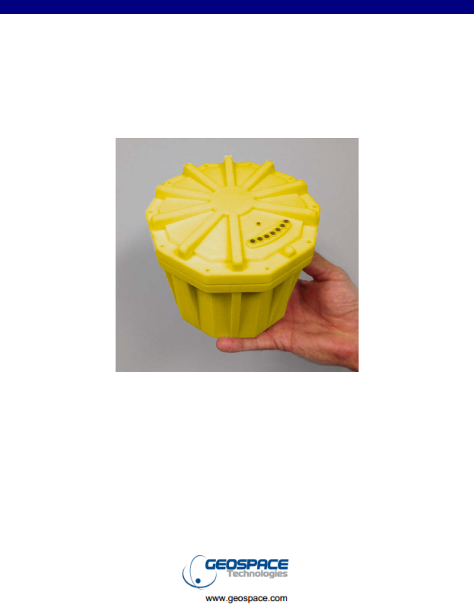
Deployment
The GCX should be deployed with the metal plate down. This provides sufficient earth grounding and
maximum cooling of the unit as well as providing the GPS receiver in the top to the unit with an ideal
“view” of the satellite constellation. The grounding spike should be fastened to the unit prior to
deployment to provide maximum earth coupling. The unit should be transported on its side in order to put
the unit into standby mode and minimize battery consumption prior to use. Once the unit is ready to be
deployed it should be flipped spike down and the GCX will immediately begin power on self-test.
The GCX will test all of its internal circuits followed immediately by an impedance test of the seismic
sensors. The LED that can be seen from the top of the GCX will flash codes to indicate the GCX’s
condition. The GCX will enable the Global Positioning System (GPD) receiver and begin to flash the
code that indicates that it is searching for satellites. Within a few seconds the GPS receiver will have
sufficient satellite information to obtain a 3 dimensional fix. The flash code will change to indicate this
condition and the GSR will now begin to acquire seismic data if it has been programmed to begin
recording immediately. See Programming below. After several minutes the internal GSR clock will be
sufficiently disciplined and the GPS receiver will be turned off. The flash code will again change to
indicate this state. See the flash codes below.
Radio Status Monitoring
A GSR may be connected to a laptop computer and used as a hub to monitor the status of any GSRs
within a 50m to 100m radius via a high frequency radio link. In this mode the laptop/hub monitors and
logs status information from all of the GSRs that it communicates with. The laptop stores the GPS
location, acquisition status, temperature, battery status and the nonvolatile memory status of each GSR.
By moving the hub throughout the seismic spread all of the GSRs in the survey may be monitored and
logged. This logging may take place during acquisition of seismic data with no adverse effect on the data
quality.
3 of 7
GCX User Manual
Flash Codes
GSR Start-up Error Codes
Critical GSR Error: LED flashes repeatedly on solid for 1 second followed by off for one second.
Critical Seis Input 1 Error: LED on solid for 1 second followed by 1 short pulse.
Critical Seis Input 2 Error: LED on solid for 1 second followed by 2 short pulses.
Critical Seis Input 3 Error: LED on solid for 1 second followed by 3 short pulses.
Critical Seis Input 4 Error: LED on solid for 1 second followed by 4 short pulses.
Critical Battery Error: LED on solid for 1 second followed by 5 short pulses.
Non-Volatile Memory Error: LED on solid for 1 second followed by 6 short pulses.
Non-Volatile Memory Full: LED on solid for 1 second followed by 7 short pulses.
GSR Run Time Codes
GPS on but no GPS fix: One LED flash per second.
GPS on with GPS fix: Two quick flashes once per second.
Recording with GPS off: One quick flash each 8 seconds.
Sleeping: Two quick flashes each 10 seconds.
Running geophone tests: LED flashes on for 10 ms 5 times per second.
Downloading
The GSR non-volatile memory may be read and cleared by removing the battery connection and
inserting the unit into one of the outlets in the GeoReaper. See the GeoReaper User Manual for
further instruction.
Programming
The GSR recording parameters such as sample rate, pre-amp gain, record mode, and testing, are
programmed and stored in non-volatile memory in the GSR by the GeoReaper. See the
GeoReaper User Manual for further instruction.
4 of 7
GCX User Manual
• Scalability - Unlimited number of channels
• Delivers high resolution data with a 24-bit delta-sigma ADC
• Built-in GPS receiver and disciplined clock
• Greater than 30 days of continuous recording
• Compatible with explosive, vibratory and impulsive energy sources
• Internal GS-ONE geophone and Extended Life Battery
• Built-in full resolution test generator
• Available as 1 or 3 channel versions
• LED Status/Deployment State Indicator
5 of 7
GCX User Manual
Geospace Combined Recorder (GCX)
______________________________________________________________________________
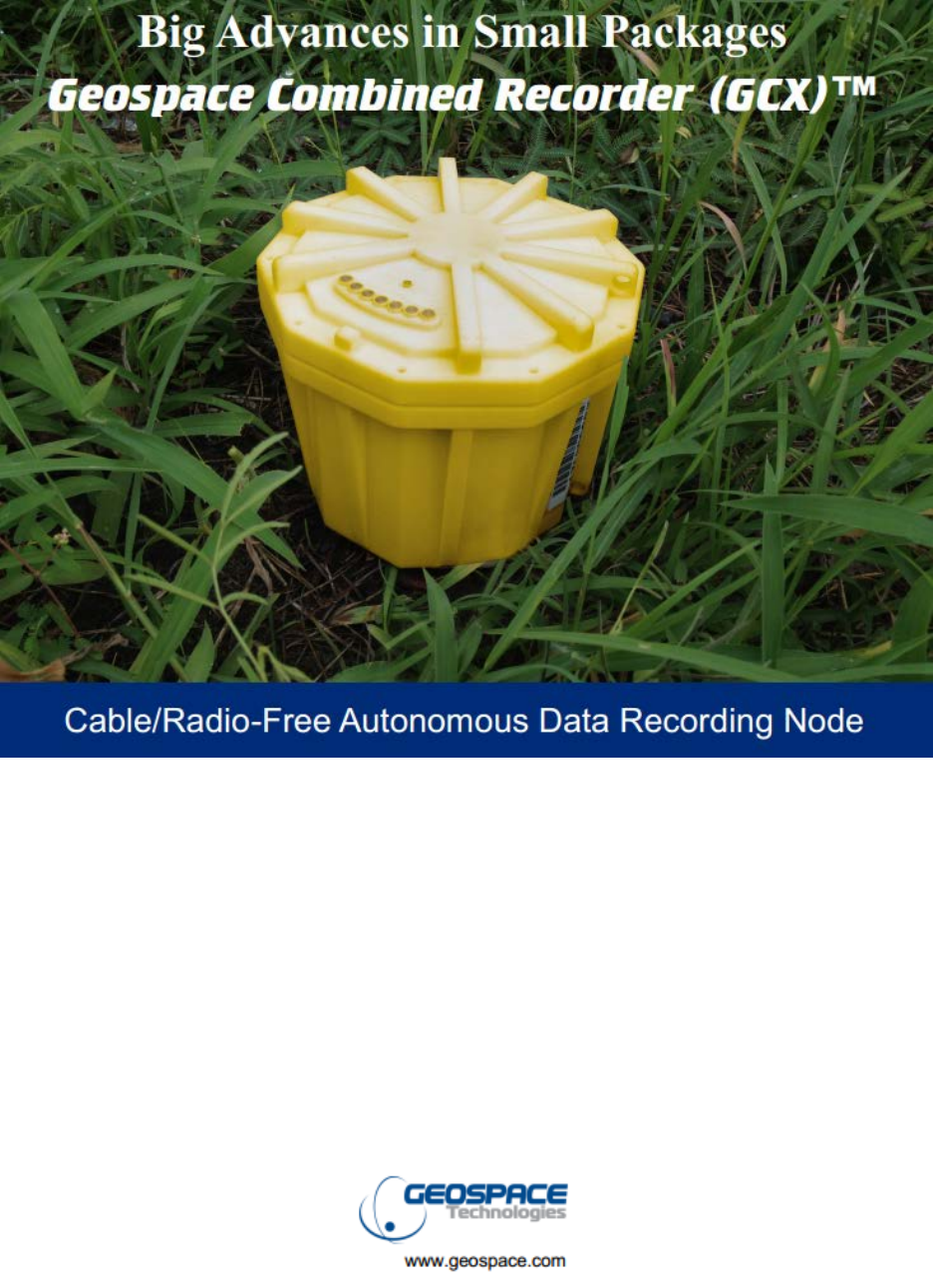
Cable/Radio-Free
Autonomous Data Recording Node
___________________________________________
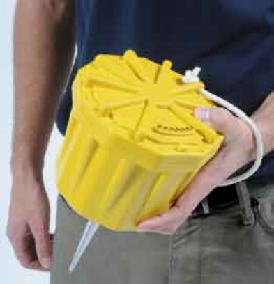
The GCX is designed for cable-free/radio-free seismic data recording. The self-contained unit includes 1
or 3 channels of 24-bit digitization, an integrated/high sensitivity GPS receiver, built-in test signal
generator, up to 16 GB per channel of non-volatile solid-state data storage, and a high-speed data port.
The unit is housed in a sealed case, with internal GS-ONE geophone and ex-tended life battery.
GCX System Tests
The seismic channel performance and sensor tests can be performed by the GCX System. The user can
choose a partial or complete set of tests that can be run in sequence and display all of the results or only
the failures. In the tests described below, the system software automatically controls the Channel Input
Switch Positions and Test Oscillator Settings during the tests. All tests can be run at all sample intervals
and preamp gains of the GCX.
- Harmonic Distortion - Gain Accuracy
- Impulse Response - Common Mode Rejection
- Equivalent Input Noise - Geophone Impedance and THD
- Instantaneous System Dynamic Range - Crossfeed (multi-channel)

6 of 7
GCX User Manual
Geospace Combined Recorder (GCX)
___________________________ Features and Spceifications___________________________
● 24-bit digital recorder ● 24-bit delta-sigma ADC
● Built-in GPS and disciplined clock ● 1 Hz to 1600 Hz freq. response
● Built-in full resolution test signal generator ● <20 μsec. of UTC (GPS clock)
● Solid-state flash memory ● Up to 16 GBytes per channel flash memory storage
● Scalability - Unlimited # of channels ● Internal extended life battery
● Greater than 30 days of continuous ● Operating Temperature: -40° C to +85° C
recording ● Humidity: 0 to 100%
● Compatible with vibratory, explosive and ● Selectable Gains:
impulsive energy sources - X1, X2, X4, X8, X16, X32, X64
● LED Status/Deployment State Indicator - 0, 6, 12, 18, 24, 30, 36 dB
● Internal GS-ONE geophone ● Sample Intervals:
● Available as 1 or 3 channel versions - 0.25, 0.5, 1, 2, 4 milliseconds
Max input signal: 1.8 VRMS @ 0 Gain System Dynamic Range @ 2 msec SI
Total Dynamic Range: 140 dB 124 dB @ Gain 0 dB
System Dynamic Range @ 0dB Gain: 123 dB @ Gain 6 dB
126 dB @ 4 msec SI 122 dB @ Gain 12 dB
124 dB @ 2 msec SI 120 dB @ Gain 18 dB
120 dB @ 1 msec SI 115 dB @ Gain 24 dB
117 dB @ .5 msec SI 110 dB @ Gain 30 dB
106 dB @ .25 msec SI 105 dB @ Gain 36 dB
Equivalent Input Noise @ 2 msec SI: Total Harmonic Distortion: 0.0005%
1.13 μV @ Gain 0 dB Common Mode Rejection: 0.001%
.58 μV @ Gain 6 dB Gain Accuracy: 1%
.33 μV @ Gain 12 dB Anti-Alias Filter:
.22 μV @ Gain 18 dB Rejection @ Nyquist: 130 dB
.19 μV @ Gain 24 dB Frequency @ -3 dB: 0.83 Nyquist
.18 μV @ Gain 30 dB Linear or Minimum Phase
.17 μV @ Gain 36 dB GPS Time Standard: <1 ppm
Input Impedance: Weight: 6 pounds
20 kohms/0.06 μf Difference Mode Max. Dimension: 6.125”dia x 5.375”h
205 kohms Common Mode Geophone Sensitivity: 2.00 V/in/s
For more information: ● Tel: 713.986.4444 ● Fax: 713.986.4445
7 of 7
GCX User Manual
Geospace Combined Recorder (GCX)
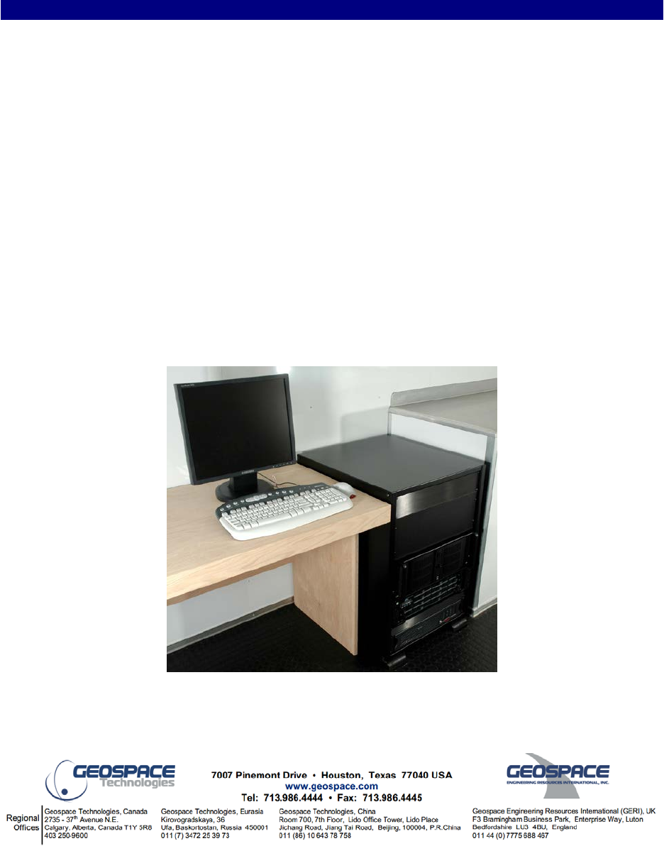
___________________ GeoRes-XTC GCX Data Management System___________________
The GeoRes-XTC consists of two embedded software modules:
GeoReaper performs pre-deployment parameter programming, i.e. sample rate, pre-amp
gain, record mode, testing, etc. and data collection via Ethernet connection to the Data Transfer
Module (DTM) and a high speed PC. A full set of instrument tests can be performed and
analyzed while the GCX is installed in the Data Transfer Module (DTM).
GeoMerge allows the system to read and import all three major components of SPS (R, S
and X records). It will merge all GCX data into SEG-D or SEG-2 files according to SPS X
records (Cross-Reference File, sorted in the same order as the Source ‘S’ File) and convert all
latitude and longitude information into the same coordinates used in the SPS files. These data
are then output to the field database (RAID memory) and/or hard media (tape, disk, etc.).
The GeoRes-XTC is compatible with third party generated SPS files.
GeoRes-XTC High Speed Computer