Getac Technology 016 A770 Notebook Computer with Wireless LAN User Manual CONTEN
Getac Technology Corp. A770 Notebook Computer with Wireless LAN CONTEN
UserManual.wiki
>
Getac Technology
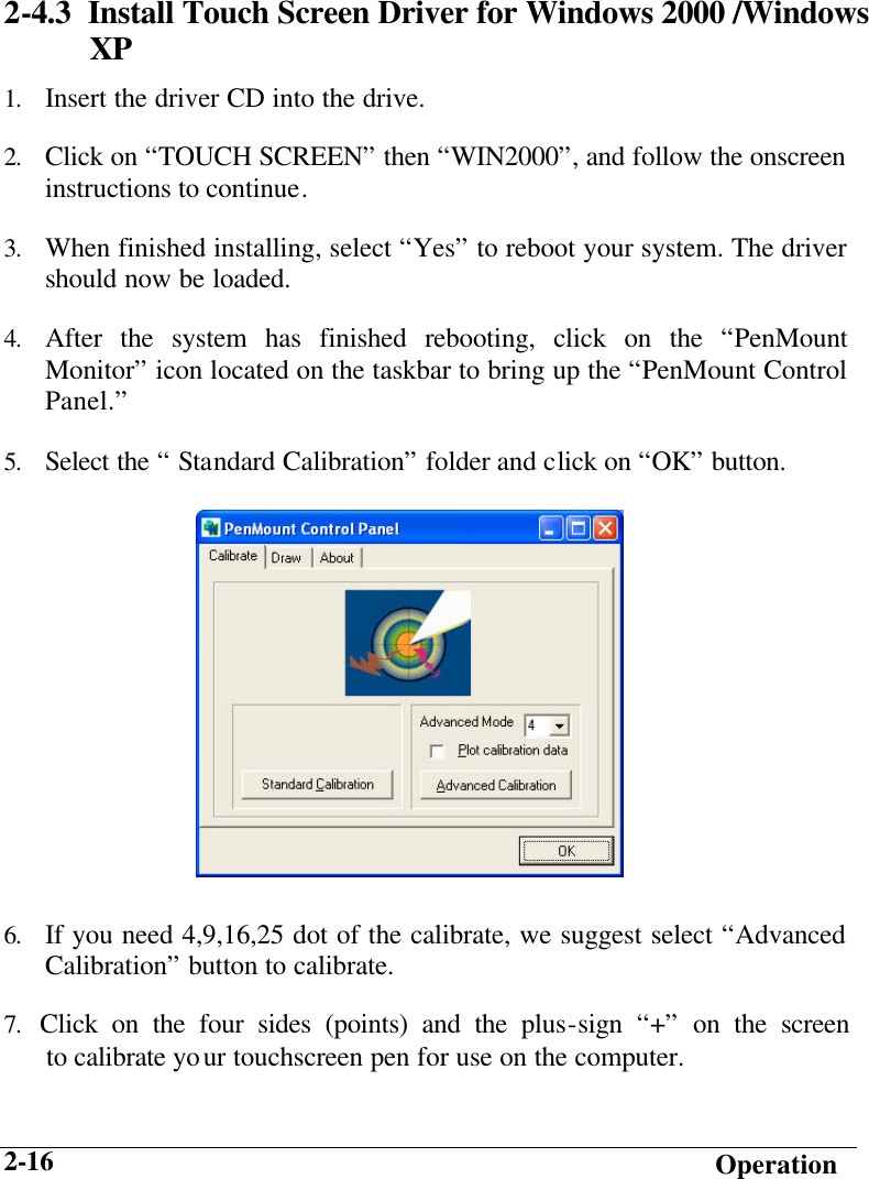
>
016 User Manual
A770 Manual
Navigation menu
Upload a User Manual
Namespaces
Wiki Guide
HTML
PDF
Info
Views
User Manual
Discussion / Help
Navigation
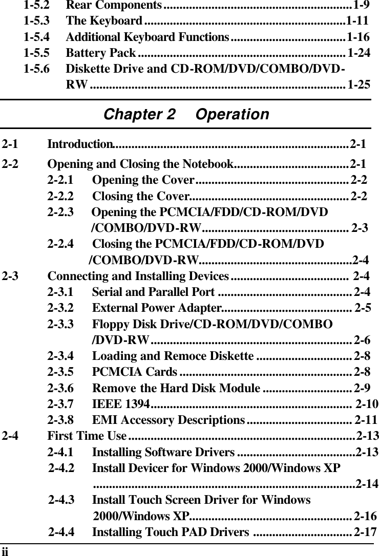
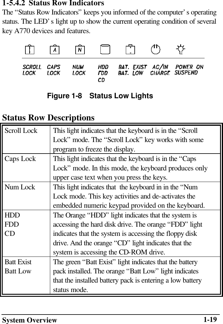
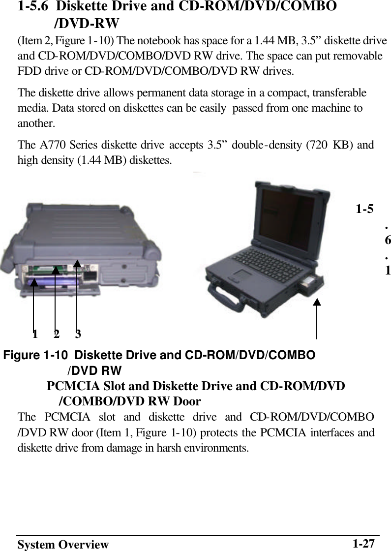
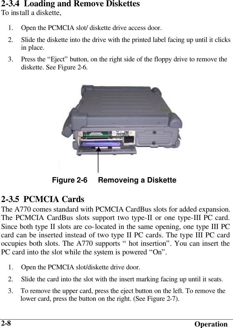
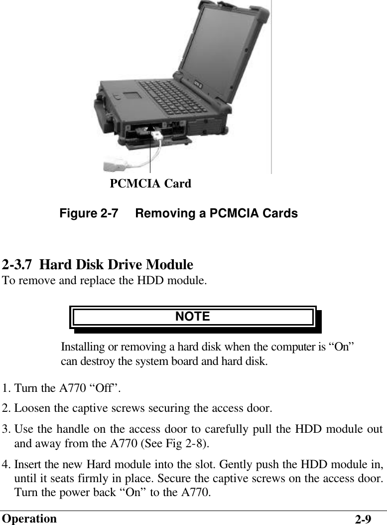
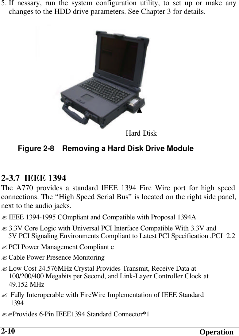
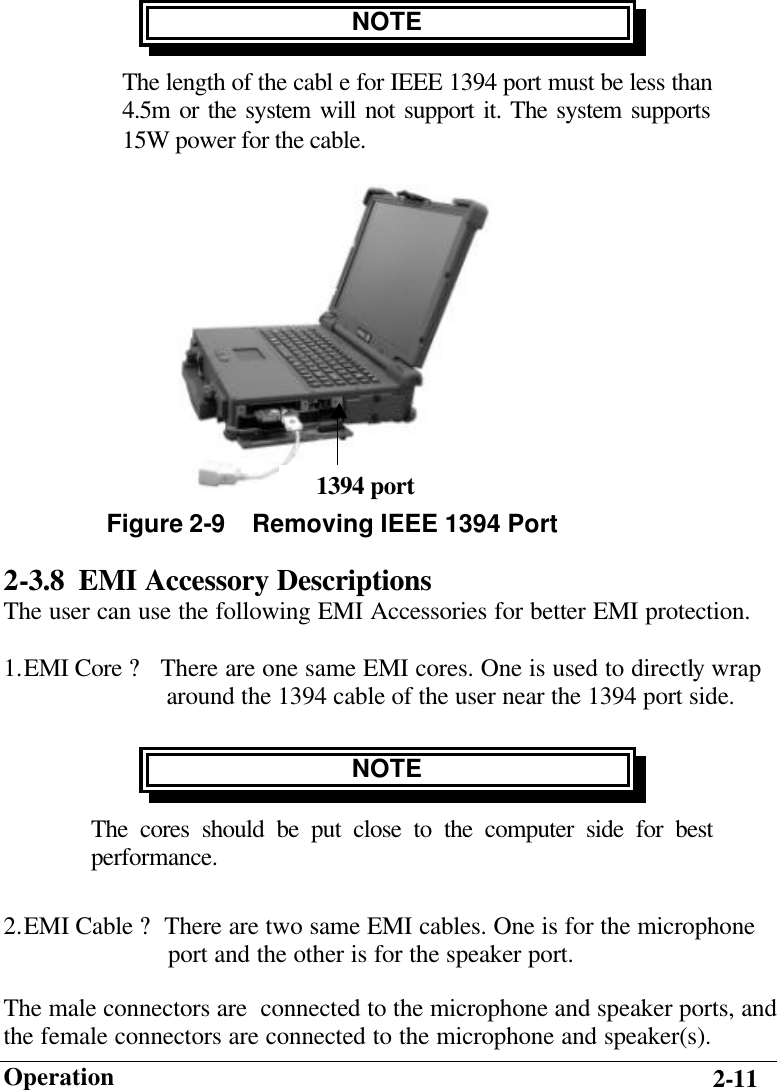
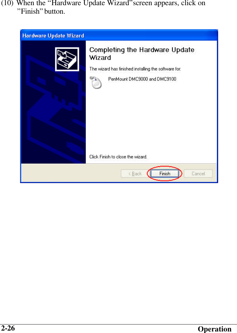
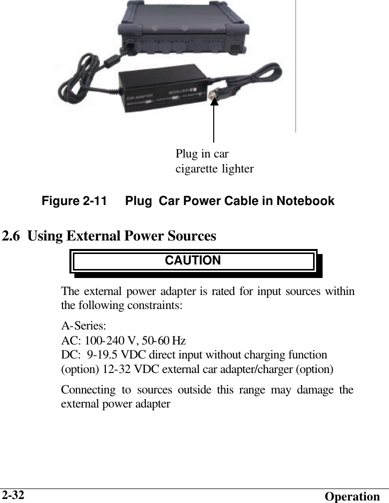
![Operation 2-25 (8)When the “Hardware Update Wizard” appears, click on “ Install the software automatically [Recommand], then click on ”Next”. (9) When the “Hardware Installation” screen appears, click on ”Continue Anyway”.](https://usermanual.wiki/Getac-Technology/016/User-Guide-512801-Page-72.png)