Getac Technology 020 Notebook PC with CDMA800, 1900 User Manual A790 0
Getac Technology Corp. Notebook PC with CDMA800, 1900 A790 0
UserManual.wiki
>
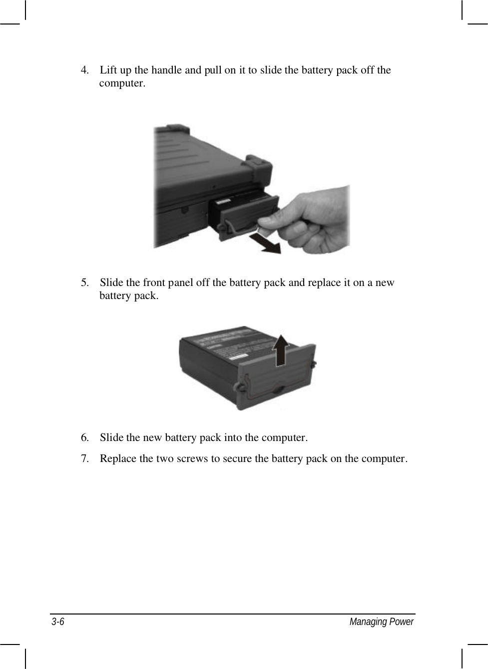
Getac Technology
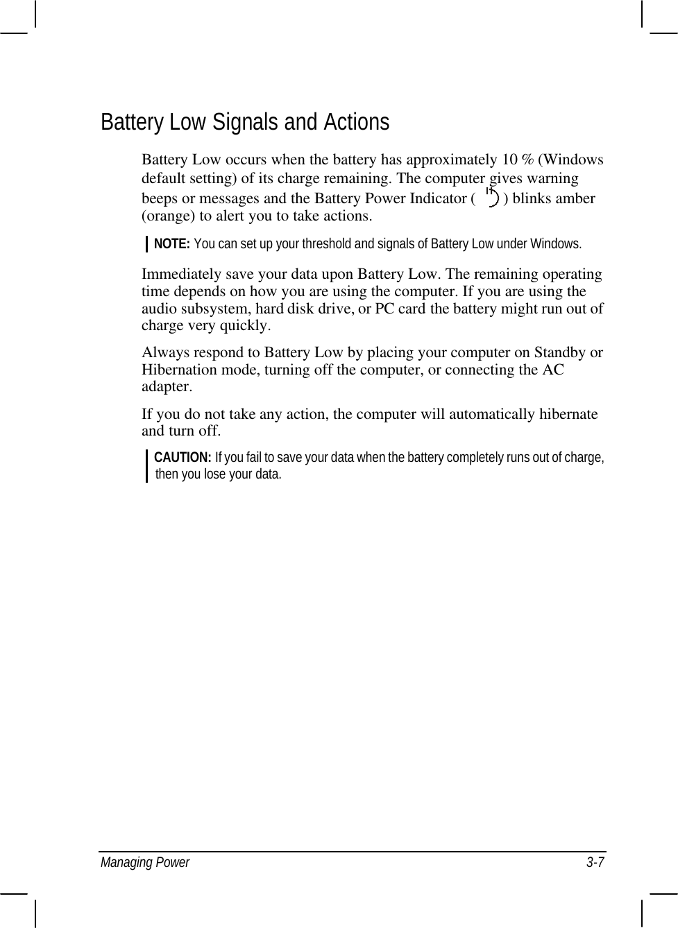
>
020 User Manual
Manual rev
Navigation menu
Upload a User Manual
Namespaces
Wiki Guide
HTML
PDF
Info
Views
User Manual
Discussion / Help
Navigation


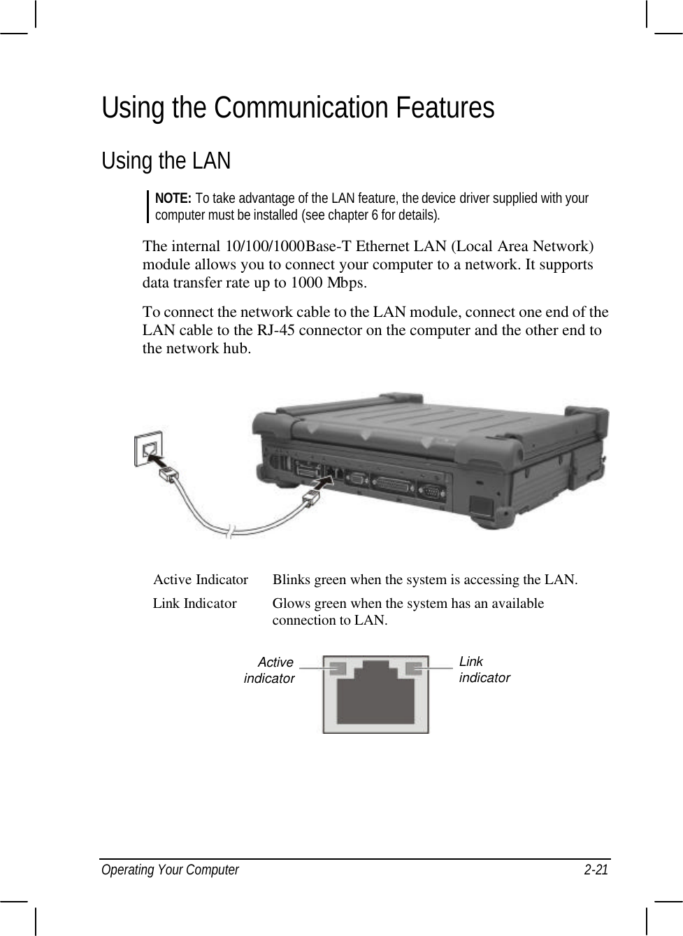
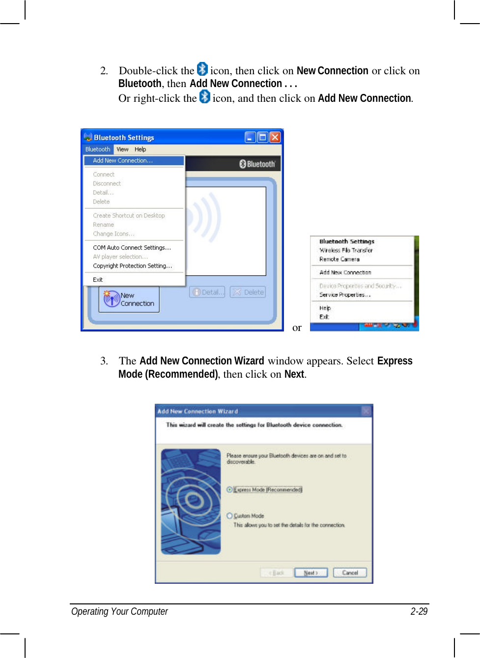
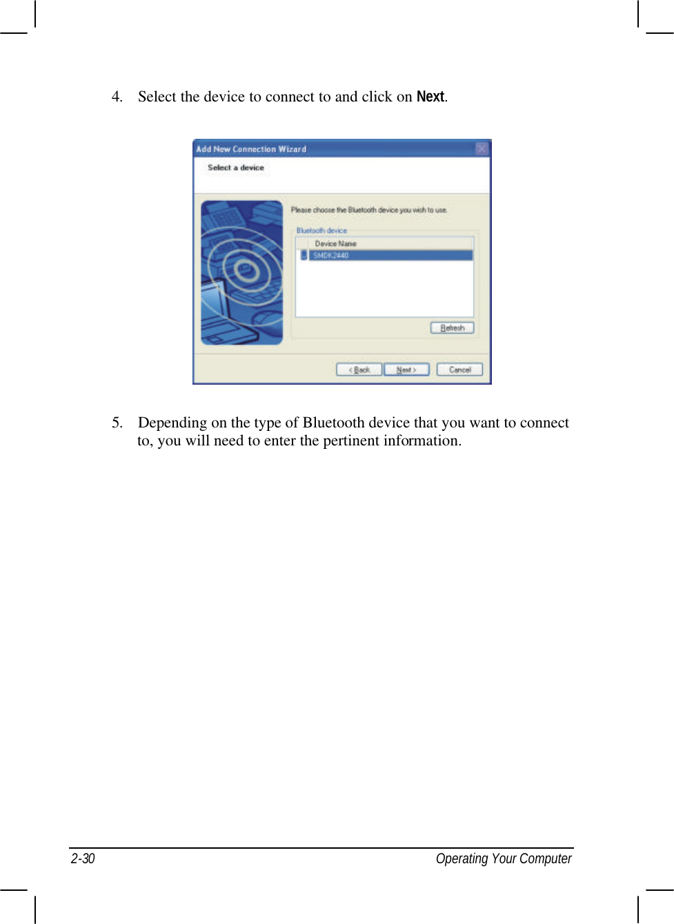
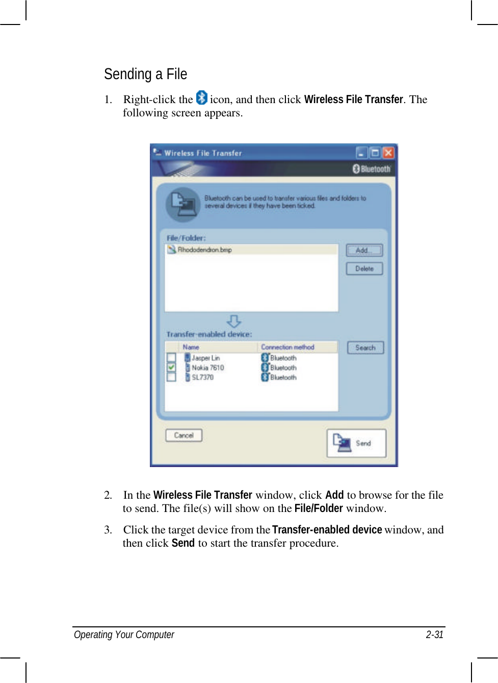
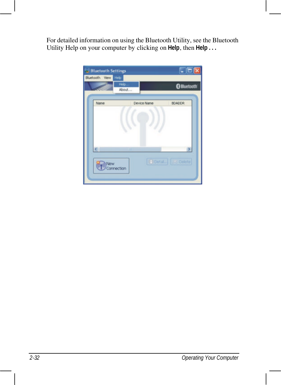


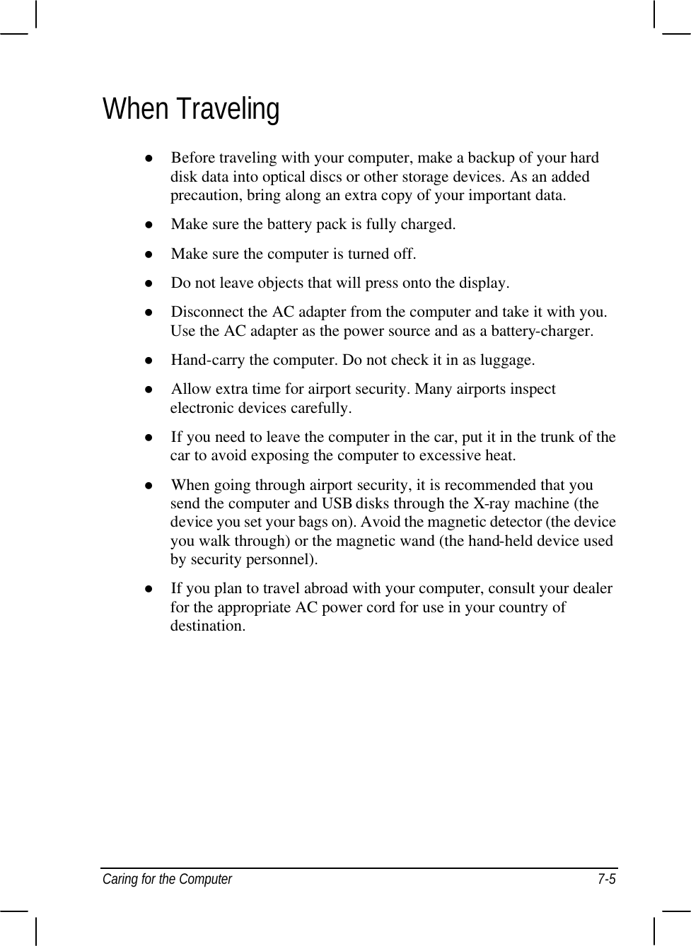

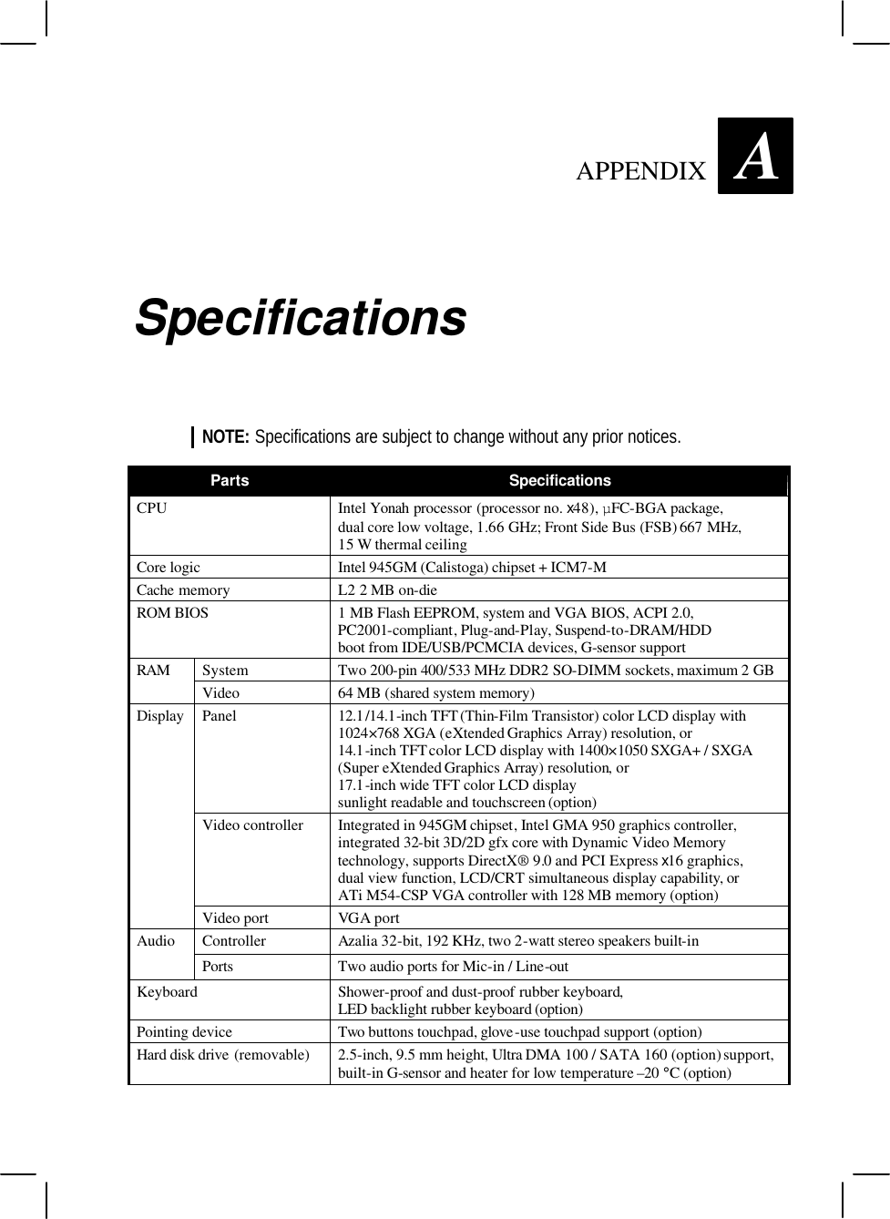
![A-2 Specifications Parts Specifications I/O ports Serial port, parallel port, IEEE 1394B port, two USB ports, IR port, port replicator, RJ-45 port, RJ-11 port, fingerprint sensor (option) Modem 56 K V.92 LAN 10/100/1000 Base-T Ethernet (reserved for TPM security function) Communications Others (option) Wireless LAN 802.11a/b/g (Intel 3945ABG) Bluetooth Class 1 V1.2 Wireless modem in Bay2 module (GPRS/GSM, CDMA) AC adapter Input: 100∼240 V AC, 50∼60 Hz universal adapter Power Battery Smart Li-ion battery 11.1 V / 9600 mah, KBC BIOS controllable Dimension (W×D×H) 12.1” version 11.8×9.5×2.3 inch (315×255×70 mm) 14.1” version 11.8×10.4×2.3 inch (315×265×70 mm) 17” version 16.1×11.7×2.3 inch (410×296×70 mm) Weight 12.1” version 12.9 lb (5.9 kg) 14.1” version 13.2 lb (6 kg) 17” version 18.7 lb (8.5 kg) Temperature Operating: 0 °C (32 °F) to 60 °C (140 °F) With HDD heater: –20 °C (–4 °F) to 60 °C (140 °F) option Storage: –40 °C (–40 °F) to 70 °C (158 °F) Humidity Operating: 5 % to 95 % RH, non-condensing Altitude Operating: 15,000 ft Storage: 40,000 ft (2,000 ft/min change rate) Shock Operating: 15 g, 11 ms, half sine wave Storage: 50 g, 11 ms, half sine wave Vibration Operating: 10~500 Hz 0.075 mm / 1 g (highway truck vibration exposure) Storage: 10~500 Hz 0.15 / 2 g (general minimum integrity exposure] Drop Survives 3 ft drop on wood 26 times (only for 12.1” and 14.1” version) Environment ESD (electrostatic discharge) Air discharge: 0~8 KV (included) no error 8~15 KV allow soft error Contact discharge: 0~4 KV (included) no error 4~8 KV allow soft error](https://usermanual.wiki/Getac-Technology/020/User-Guide-739077-Page-121.png)