Getac Technology 030 Notebook with WLAN User Manual W190 manual

Getac Technology Corp. Notebook with WLAN W190 manual

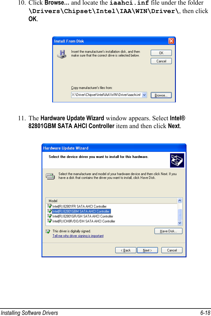
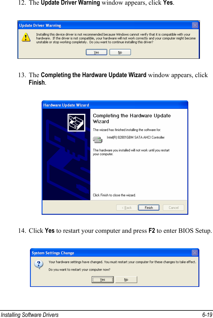
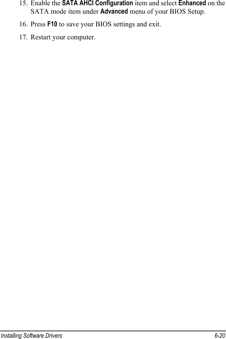
Users Manual Revised

    User’s Manual   Notebook Personal Computer  (With Intel WM3945ABG WLAN Module) Model:W190 MITAC Technology Corporation          (February 2008)
                   TRADEMARKS All brand and product names are trademarks or registered trademarks of their respective companies. NOTE The information in this manual is subject to change without notice.
  ENERGY STAR® is a government program that offers businesses and consumers energy-efficient solutions, making it easy to save money while protecting the environment for future generations. Please reference ENERGY STAR® related information from www.energystar.gov. As an ENERGY STAR® Partner, MiTAC Technology Corporation has determined that this product meets the ENERGY STAR® guidelines for energy efficiency. An ENERGY STAR® qualified computer uses 70% less electricity than computers without enabled power management features.  Earning the ENERGY STAR® z When every home office is powered by equipment that has earned the ENERGY STAR®, the change will keep over 289 billion pounds of greenhouse gases out of the air. z If left inactive, ENERGY STAR® qualified computers enter a low-power mode and may use 15 watts or less. New chip technologies make power management features more reliable, dependable, and user-friendly than even just a few years ago. z Spending a large portion of time in low-power mode not only saves energy, but helps equipment run cooler and last longer. z Businesses that use ENERGY STAR® enabled office equipment may realize additional savings on air conditioning and maintenance.
 z Over its lifetime, ENERGY STAR® qualified equipment in a single home office (e.g., computer, monitor, printer, and fax) can save enough electricity to light an entire home for more than 4 years. z Power management (“sleep settings”) on computers and monitors can result in much savings annually.  Remember, saving energy prevents pollution Because most computer equipment is left on 24 hours a day, power management features are important for saving energy and are an easy way to reduce air pollution. By using less energy, these products help lower consumers’ utility bills, and prevent greenhouse gas emissions.
 i Table of Contents Preface ........................................................................................v Notational Conventions.......................................................vi Chapter 1  Getting Started...................................................1-1 Getting the Computer Running ............................................ 1-2 Unpacking ........................................................................ 1-2 Connecting to AC Power ................................................. 1-2 Opening and Closing the Cover ....................................... 1-4 Turning On and Off the Computer................................... 1-4 Taking a Look at the Computer............................................ 1-6 Right-Side Components ................................................... 1-6 Left-Side Components ..................................................... 1-7 Rear Components ............................................................. 1-8 Front Components............................................................ 1-9 Bottom Components....................................................... 1-10 Top-open Components ................................................... 1-11 Where to Go from Here...................................................... 1-14 Chapter 2  Operating Your Computer.................................2-1 Starting and Stopping the Computer .................................... 2-2 Starting the Computer ...................................................... 2-2 Stopping the Computer .................................................... 2-2 Using the Keyboard.............................................................. 2-4 Typewriter Keys............................................................... 2-4 Cursor-Control Keys ........................................................ 2-4 Numeric Keypad .............................................................. 2-5 Function Keys .................................................................. 2-5 Fn Key.............................................................................. 2-5
 ii Hot Keys .......................................................................... 2-5 Using the Touchpad ............................................................. 2-7 Configuring the Touchpad ............................................... 2-8 Using the Touchscreen (Optional) ....................................... 2-9 Using the Hard Disk Drive................................................. 2-10 Using the Video Features ................................................... 2-11 Configuring the Display Modes ..................................... 2-11 Using the Audio Features................................................... 2-13 Connecting Audio Devices ............................................ 2-13 Using the Communication Features ................................... 2-15 Using the Modem........................................................... 2-15 Using the LAN ............................................................... 2-15 Using the Wireless LAN ................................................ 2-16 Chapter 3  Managing Power ................................................3-1 AC Adapter .......................................................................... 3-2 Battery Pack ......................................................................... 3-3 Charging the Battery Pack ............................................... 3-3 Checking the Battery Level.............................................. 3-5 Replacing the Battery Pack .............................................. 3-5 Battery Low Signals and Actions..................................... 3-9 Power Management............................................................ 3-11 Hibernation..................................................................... 3-12 Power-Saving Tips ............................................................. 3-13 Chapter 4  Expanding Your Computer ...............................4-1 Connecting an External Monitor .......................................... 4-2 Connecting a Serial Device .................................................. 4-3 Connecting a USB Device.................................................... 4-4 Using PC Cards .................................................................... 4-5 CardBus Support .............................................................. 4-5 Inserting and Removing a PC Card.................................. 4-5 Using the Port Replicator (Optional).................................... 4-7 System Memory Upgrade..................................................... 4-8
 iii Chapter 5  Using BIOS Setup ..............................................5-1 When and How to Use BIOS Setup ..................................... 5-2 When to Use..................................................................... 5-2 Starting BIOS Setup......................................................... 5-2 Moving Around and Making Selections .......................... 5-3 Main Menu ........................................................................... 5-4 Advanced Menu ................................................................... 5-5 Security Menu ...................................................................... 5-6 Boot Menu............................................................................ 5-7 Exit Menu............................................................................. 5-8 When and How to Use the System Recovery Feature.......... 5-9 When to Use..................................................................... 5-9 Starting System Recovery ................................................ 5-9 Chapter 6  Installing Software Drivers................................6-1 How to Use the Driver Disc ................................................. 6-2 Touchscreen Utility.......................................................... 6-5 SATA AHCI Driver ....................................................... 6-10 Chapter 7  Caring for the Computer ...................................7-1 Protecting the Computer....................................................... 7-2 Using the Cable Lock....................................................... 7-2 Using an Anti-Virus Strategy........................................... 7-2 Taking Care of the Computer............................................... 7-3 Location Guidelines ......................................................... 7-3 General Guidelines........................................................... 7-3 Cleaning Guidelines ......................................................... 7-4 Battery Pack Guidelines................................................... 7-4 When Traveling.................................................................... 7-5 Chapter 8  Troubleshooting.................................................8-1 Preliminary Checklist........................................................... 8-2 Solving Common Problems.................................................. 8-3 Battery Problems.............................................................. 8-4 Display Problems ............................................................. 8-4
 iv Hardware Device Problems.............................................. 8-5 Hard Disk Drive Problems ............................................... 8-6 Keyboard, Mouse, and Touchpad Problems .................... 8-7 LAN Problems ................................................................. 8-7 WLAN Problems.............................................................. 8-8 Modem Problems ............................................................. 8-9 PC Card Problems .......................................................... 8-10 Power Management Problems........................................ 8-10 Software Problems ......................................................... 8-11 Sound Problems ............................................................. 8-12 Startup Problems ............................................................ 8-13 Other Problems............................................................... 8-13 Resetting the Computer...................................................... 8-14 Appendix A  Specifications ................................................... A-1 Appendix B  Regulatory Information .................................... B-1 On the Use of the System.....................................................B-2 Class B Regulations .........................................................B-2 Safety Notices ..................................................................B-3 On the Use of the RF Device................................................B-6 USA and Canada Safety Requirements and Notices........B-6 European Union CE Marking and Compliance Notices ..B-9 电子信息产品有毒有害物质或元素名称及含量标示....B-13
 v Preface This manual contains information that will help you operate the computer. It is divided into 8 chapters and 2 appendices. z Chapter 1, Getting Started, takes you through the process of setting up the computer and identifying its external components. z Chapter 2, Operating Your Computer, tells you how to use the computer’s components and features. z Chapter 3, Managing Power, provides information on power. z Chapter 4, Expanding Your Computer, provides information on installing and using peripheral devices. z Chapter 5, Using BIOS Setup, describes the BIOS Setup program that configures the computer’s BIOS settings. z Chapter 6, Installing Software Drivers, describes how to install the drivers and utilities supplied with the computer. z Chapter 7, Caring for the Computer, gives you tips in care and maintenance. z Chapter 8, Troubleshooting, gives solutions to common problems you may encounter when using the computer. z Appendix A, Specifications, gives a brief specification of the computer. z Appendix B, Regulatory Information, provides regulatory statements and safety notices on your computer.
 vi Notational Conventions Throughout this manual, the following conventions are used to distinguish elements of text. NOTE: identifies additional information that requires special attention.  CAUTION: identifies important information that, if not followed, may result in loss of data or damage to the computer.  Keyboard keys are shown in a bold typeset. For example: Press the Enter key to complete. When keys are joined by a plus sign (+), press the first key, and, while keeping the first key down, press the remaining keys, finally release all the keys. When necessary, keys are also shown in graphics. A title, command, setup item, or button that you can see on the screen is shown in boldface. A value or an option that you can select for a setup item is shown in italic. For example: Select Power Schemes, set it to Portable/Laptop, and then click the OK button.
 Getting Started  1-1 Chapter   1  Getting Started Congratulations on purchasing this ruggedized computer. This chapter first tells you step by step how to get the computer up and running. You will find instructions for these procedures: z Unpacking z Connecting to AC power z Opening and closing the cover z Turning on the computer z Turning off the computer Then, you will find a section briefly introducing the external components of the computer. And the last section navigates you to the information you may need after the computer is ready for use.  CHAPTER
 Getting Started  1-2 Getting the Computer Running This section guides you through the procedures for getting the computer ready for operation. Unpacking After unpacking the shipping carton, you should find these standard items: z Notebook computer z Accessories: − AC adapter − AC power cord − Driver disc − Touchscreen pen (option) − External battery charger (option) − Car adapter/charger (option) − Vehicle docking (option) − Office docking (option) Inspect all the items. If any item is damaged or missing, notify your dealer immediately. Keep the shipping carton and packing materials in case you need to ship or store the computer in the future. Connecting to AC Power The computer operates either on the external AC power or internal battery power. It is suggested that you use AC power when you start up the computer for the very first time. CAUTION: Use only the AC adapter included with your computer. Using other AC adapters may damage the computer.  1. Make sure that the computer is turned off.
 Getting Started  1-3 2. Plug the DC cord of the AC adapter to the power connector of the computer (n). 3. Plug the female end of the AC power cord to the AC adapter and the male end to an electrical outlet (o).  4. When the AC adapter is connected, power is being supplied from the electrical outlet to the AC adapter and onto your computer. Now, you are ready to turn on the computer.  CAUTION: z When you disconnect the AC adapter, disconnect from the electrical outlet first and then from the computer. A reverse procedure may damage the AC adapter or the computer. z When unplugging the connector, always hold the plug head. Never pull on the cord.  NOTE: When the AC adapter is connected, it also charges the battery pack. For information on using battery power, see Chapter 3.
 Getting Started  1-4 Opening and Closing the Cover Open the top cover by pulling the cover latch (bottom part) outward using your finger, and lifting up the cover. You can tilt the cover forward or backward for optimal viewing clarity.  Turning On and Off the Computer Turning On 1. Make sure that the computer is connected to AC power.
 Getting Started  1-5 2. Press the power button ( ).  3. Each time the computer is turned on, it performs a Power-On Self Test (POST), and the operating system such as Windows should start. Turning Off To turn off the computer power, use the “Shut Down” command of your operating system. NOTE: There are other ways you can stop the computer so that you will be back to where you left off when you next turn on the computer. (See “Stopping the Computer” in Chapter 2 for information.)  CAUTION: If you have to turn the computer on again immediately after turning it off, wait for at least five seconds. Turning the computer off and on rapidly can damage it.
 Getting Started  1-6 Taking a Look at the Computer This section identifies the external components of the computer and briefly describes the function of each component. NOTE: Depending on the model you purchased, the appearance of your computer may not be exactly the same as those shown in this manual. Right-Side Components  Ref  Component  Description n PCMCIA Slot Accepts a PC Card for additional functions. o RJ-45 Connector  Connects the LAN cable. p RJ-11 Connector Connects the telephone line. q USB Port  Connects a USB device, such as a flash disk, printer, digital camera, joystick, and more.
 Getting Started  1-7 Left-Side Components  Ref  Component  Description n Audio Output Connector Connects a set of headphones, external speakers with amplifier, or an audio recording device. o Microphone Connector Connects an external microphone.
 Getting Started  1-8 Rear Components  Ref  Component  Description n USB Port  Connects a USB device, such as a flash disk, printer, digital camera, joystick, and more. o VGA Connector Connects an external display monitor. p Serial Connector Connects a serial mouse or serial communication device. q Power Connector  Connects the AC adapter.
 Getting Started  1-9 Front Components  Ref  Component  Description n Top Cover Latch  Locks the top cover. o Notched Hole  Allows you to hook the computer to the docking station. p Touchscreen Pen  Provides a convenient way to use the touchscreen. Can be stretched for better grip and handling. q Handle Provides a convenient way to carry the computer anywhere.
 Getting Started  1-10 Bottom Components  Ref  Component  Description n Battery Cover Latch Locks the battery pack compartment. o Battery Pack Compartment Inside is the battery pack that supplies power to your computer when external power is not connected. p Speaker  Sends out sound and voice from the computer. q Notched Holes  Secures the computer to the docking station. r Expansion Bus Connector Inside is the expansion bus connector for using a Port Replicator.
 Getting Started  1-11 Top-open Components  Ref  Component  Description n LCD Screen  Displays the output of the computer. o Power Button   Turns the computer power ON and OFF. p Keyboard  Serves as the data input device of the computer. q Touchpad  Serves as the pointing device of the computer.
 Getting Started  1-12 Ref  Component  Description Device Indicators Shows the current status of the computer’s devices.  Caps Lock Indicator  Num Lock Indicator  Scroll Lock Indicator  LAN 10/100/1000Base-T Indicator r   Hard Disk Drive Indicator Device Indicators Shows the current status of the computer’s devices. Battery State Indicator  Glows amber when battery charge is 10 % or lower. System State Indicator Glows green when the computer is powered on.  Glows amber when the computer is in Sleep/Standby mode. Battery Charge Indicator Glows green when the battery is fully charged. Glows amber when the battery is being charged.  Is off when battery has no charge left, AC adapter is connected, and computer is powered-on. AC Power Indicator s   Glows green when computer is connected to AC power and is powered-on.
 Getting Started  1-13 Where to Go from Here As your computer is ready for operation, you may want to do any of the following now: For this purpose...  Do this... To know more about the computer...  Go on to the next chapter. To install the operating system if your dealer has not already done so... See the operating system manual. To know more about the operating system... Read the operating system manual. To install the drivers if your dealer has not already done so... See Chapter 6. To set a power-on password…  See “Security Menu” in Chapter 5. To charge the battery pack for the first time... See “Charging the Battery Pack” in Chapter 3.
 Operating Your Computer  2-1 Chapter   2  Operating Your Computer This chapter provides information about the use of the computer. If you are new to computers, reading this chapter will help you learn the operating basics. If you are already a computer user but are new to notebook computers, you may choose to read only the parts containing information unique to your computer. Described in this chapter are the operating basics of these components: z Keyboard z Touchpad z Touchscreen (option) z Hard disk drive And these features: z Starting and stopping the computer z Video features z Audio features z Communication features  CHAPTER
 Operating Your Computer  2-2 Starting and Stopping the Computer There are a number of ways to start and stop the computer. Starting the Computer You always start the computer using the power button. A computer starts up with an operating system (OS) existing on the storage device such as the hard disk. The computer will automatically load the OS after you turn it on. This process is called booting. NOTE: An operating system is the platform for all your software application programs to run on. The most widely used operating system today is Microsoft Windows XP. Stopping the Computer When you finish a working session, you can stop the computer by turning off the power or leaving the computer in Standby or Hibernation mode: To stop in this mode... Do this...  To start up or resume again Off  Follow the shutdown procedure of your operating system. This can prevent loss of unsaved data or damage to your software programs. If the system is locked up because of hardware or software problems, press the power button to turn off the computer. Press the power button. Standby Depending on your settings in Windows, you can place the computer in Standby mode by: •  Closing the display cover • Pressing the Fn+F10 hot key •  Pressing the power button Press any key.     Hibernation  Depending on your settings in Windows,  Press the power
 Operating Your Computer  2-3 To stop in this mode... Do this...  To start up or resume again you can place the computer in Hibernation mode by: •  Closing the display cover • Pressing the Fn+F10 hot key •  Pressing the power button button.  If you choose to stop in Standby or Hibernation mode, you can return to where you left off the next time you start up the computer. (See “Power Management” in Chapter 3 for more information.)
 Operating Your Computer  2-4 Using the Keyboard Your keyboard has all the standard functions of a full-sized computer keyboard plus a Fn key added for specific functions. The standard functions of the keyboard can be further divided into four major categories: z Typewriter keys z Cursor-control keys z Numeric keys z Function keys Typewriter Keys Typewriter keys are similar to the keys on a typewriter. Several keys are added such as the Ctrl, Alt, Esc, and lock keys for special purposes. When the lock keys (Caps Lock, Num Lk, and Scroll Lk) are pressed, their corresponding indicators light up. The Control (Ctrl) / Alternate (Alt) key is normally used in combination with other keys for program-specific functions. The Escape (Esc) key is usually used for stopping a process. Examples are exiting a program and canceling a command. The function depends on the program you are using. Cursor-Control Keys NOTE: The word “cursor” refers to the indicator on the screen that lets you know exactly where on your screen anything you type will appear. It can take the form of a vertical or horizontal line, a block, or one of many other shapes.
 Operating Your Computer  2-5 Numeric Keypad A 15-key numeric keypad is embedded in the typewriter keys as shown next: Numeric keys facilitate entering of numbers and calculations. When Num Lock is on, the numeric keys are activated; meaning you can use these keys to enter numerals. NOTE: z When the numeric keypad is activated and you need to type the English letter in the keypad area, you can turn Num Lock off or you can press Fn and then the letter without turning Num Lock off. z Some software may not be able to use the numeric keypad on the computer. If so, use the numeric keypad on an external keyboard instead. Function Keys On the top row of the keys are the function keys: F1 to F12. Function keys are multi-purpose keys that perform functions defined by individual programs. Fn Key The Fn key, at the lower left corner of the keyboard, is used with another key to perform the alternative function of a key. The letter “Fn” and the alternative functions are identified by the color of blue on the keytop. To perform a desired function, first press and hold Fn, then press the other key. Hot Keys Hot keys refer to a combination of keys that can be pressed any time to activate special functions of the computer. Most hot keys operate in a cyclic way. Each time a hot key combination is pressed, it shifts the corresponding function to the other or next choice.
 Operating Your Computer  2-6 You can easily identify the hot keys with the icons imprinted on the keytop.  Euro Symbol You can press the euro dollar sign   on various keyboards. z To press the euro sign on a United States-International keyboard, hold down the Alt Gr key and press 5 (which has an euro sign on it). z To press the euro sign on a standard United States keyboard, hold down either of the Alt keys and type 0128 on the numeric keypad part of your keyboard. z To press the euro sign on an UK keyboard, hold down the Alt Gr key and press 4 (which has an euro sign on it). Windows Keys The keyboard has two keys that perform Windows-specific functions:  Windows Logo key and   Application key. The   Windows Logo key opens the Start menu and performs software-specific functions when used in combination with other keys. The   Application key usually has the same effect as a right mouse click. (See your Windows manual for more information.)
 Operating Your Computer  2-7 Using the Touchpad CAUTION: Do not use a sharp object such as a pen on the touchpad. Doing so may damage the touchpad surface.  NOTE: For optimal performance of the touchpad, keep your fingers and the pads clean and dry. When tapping on the pad, tap lightly. Do not use excessive force.  The touchpad is a pointing device that allows you to communicate with the computer by controlling the location of the pointer on the screen and making selection with the buttons. The touchpad consists of a rectangular pad (work surface) and a left and right buttons. To use the touchpad, place your forefinger or thumb on the pad. The rectangular pad acts like a miniature duplicate of your display. As you slide your fingertip across the pad, the pointer (also called cursor) on the screen moves accordingly. When your finger reaches the edge of the pad, simply relocate yourself by lifting the finger and placing it on the other side of the pad. Here are some common terms that you should know when using the touchpad: Term  Action Point  Move your finger on the pad until the cursor points to the selection on the screen. Click  Press and release the left button. –or– Tap gently anywhere on the pad. Double-click  Press and release the left button twice in quick succession. –or– Tap twice on the pad rapidly.
 Operating Your Computer  2-8 Term  Action Drag and drop Press and hold the left button, then move your finger until you reach your destination (drag). Finally, release the button (drop) when you finish dragging your selection to the destination. The object will drop into the new location. –or– Gently tap twice on the pad and on the second tap, keep your finger in contact with the pad. Then, move your finger across the pad to drag the selected object to your destination. When you lift your finger from the pad, the selected object will drop into place. Scroll  To scroll is to move up and down or left and right in the working area on the screen. To move vertically, place your finger on the right or left edge of the pad and slide your finger up and down along the edge. To move horizontally, place your finger on the top or bottom edge of the pad and slide your finger left and right. This function works only after you install the touchpad driver supplied with the computer and it may not work for all applications. TABLE NOTE: If you swap the left and right buttons, “tapping” on the touchpad as an alternative method of pressing the left button will no longer be valid. Configuring the Touchpad You may want to configure the touchpad to suit your needs. For example, if you are a left-handed user, you can swap the two buttons so that you can use the right button as the left button and vise versa. You can also change the size of the on-screen pointer, the speed of the pointer, and so on. To configure the touchpad, you can use the standard Microsoft or IBM PS/2 driver if you are using Windows.
 Operating Your Computer  2-9 Using the Touchscreen (Optional) NOTE: z Your computer comes with an optional touchscreen function. z Make sure the touchscreen driver has been installed properly (see chapter 6 for details).  CAUTION: Do not use a sharp object such as a ballpoint pen or pencil on the touchscreen. Doing so may damage the touchscreen surface. Use your finger or the included touchscreen pen (option).  The touchscreen is a touch-sensitive device that allows you to easily use the computer without a mouse or touchpad to communicate with the computer by controlling the location of the pointer on the screen and making selection with the buttons. Here are some common terms that you should know when using the touchscreen: Term  Action Click/Point  Tap gently on the touchscreen. Double-click  Tap twice on the touchscreen rapidly. Drag and drop Press lightly on the touchscreen and move your finger until you reach your destination (drag). Finally, release your finger (drop) when you finish dragging your selection to the destination. The object will drop into the new location.
 Operating Your Computer  2-10 Using the Hard Disk Drive WARNING: DO NOT replace the hard disk drive by yourself. Refer all servicing to qualified personnel or your dealer.  Your computer comes with a hard disk drive as drive C. A hard disk drive is a storage device with non-removable, rotating, magnetic storage platters inside it. It is where your operating system and application software programs are stored. Your hard disk drive is a 2.5-inch SATA (serial ATA) hard disk drive. This type of drive embodies the latest in fast, reliable mass storage by integrating all the control circuitry necessary for operation directly onto the drive itself. You can enable the Advanced Host Controller Interface (AHCI), a programming interface for SATA host controllers. AHCI defines transactions between the SATA controller and software and enables advanced performance and usability with SATA. When the SATA AHCI mode is enabled (see chapter 5 under the Advanced Menu “SATA AHCI Configuration” item), your system can support SATA native command queuing, aggressive power management, and so on. NOTE: To use the AHCI feature, the AHCI driver supplied with your computer must be installed (see chapter 6 for details).  The system may come with an optional heater that automatically turns on for low temperature operation. NOTE: To use the HDD heater feature, the MTCCTRL driver supplied with your computer must be installed (see chapter 6 for details).  CAUTION: z Make regular backups of your data files from your hard disk drive to USB flash disks or other storage media. z Never turn off or reset the computer while the hard disk drive in-use indicator is on.
 Operating Your Computer  2-11 Using the Video Features The video subsystem of your computer features: z 12.1-inch wide TFT (Thin-Film Transistor) color LCD display with 1024×768 XGA resolution z Simultaneous display on LCD and external monitor, which is useful when you have a presentation as you can control the screen from your computer and face the audience at the same time (option) z Multi-display capability, which allows you to expand your desktop on the screen to another display device so that you have more desktop space to work on z Power Management z Sunlight-readable LCD display (option) NOTE: z Before using the multi-display capability or taking advantage of the enhanced video capabilities, the device driver supplied with your computer must be installed. (See chapter 6 for details.) z The computer enters the Standby or Hibernation mode when the LCD is closed. If you want to use the computer with the LCD closed, set Do Nothing to the “When I close the lid of my portable computer” option in the Power Options Properties. Thus the computer does not enter the Standby or Hibernation mode when the LCD is closed. Configuring the Display Modes NOTE: When using an external CRT monitor, the resolution depends on the CRT monitor’s supported resolution.  Your computer has been set to a default resolution and number of colors before shipment. You can view and change display settings through your operating system. See your operating system documentation or online help for specific information. For displaying in higher resolutions, you can connect an external monitor that supports higher resolutions. (See “Connecting an External Monitor” in Chapter 4 for more information.)
 Operating Your Computer  2-12
 Operating Your Computer  2-13 Using the Audio Features NOTE: z To take advantage of the enhanced audio capabilities, the device driver supplied with your computer must be installed. (See chapter 6 for details.) z If you experience interference while recording, try lowering the microphone recording volume.  The audio subsystem of your computer features: z Built-in sound system for recording and playing sound on your computer z Azalia interface (high density audio codec) z Speaker (located on bottom side), and z External audio connectors Ways of playing and recording sound vary with the operating system used. See your operating system documentation or online help for specific information. Connecting Audio Devices For higher audio quality, you can send or receive sound through external audio devices. NOTE: After connecting an external audio device, make sure that you specify the use of the correct audio device in Windows.  z Audio Output Connector  can be connected to speakers, headphones, or earphone set. z Microphone Connector  can be connected to an external microphone for recording voice or sound. NOTE: When using the external speakers/headphones or microphone, you cannot use the internal one.
 Operating Your Computer  2-14 Using the Communication Features Using the Modem NOTE: To take advantage of the modem feature, the device driver supplied with your computer must be installed. (See chapter 6 for details.)  The internal 56 K fax/data modem allows you to use the telephone line to communicate with others by fax, email, or connect to an online service or bulletin board. To connect the telephone line to the modem, connect one end of the modem cable to the RJ-11 connector on the computer and the other end to the phone line. NOTE: z When using the communication software, you may have to disable power management. z Set the COM port of the modem to COM3. z Set parameters such as modem speed (baud rate) and line type (pulse dialing or tone dialing). z Do not enter the Standby mode when using the communication software.  Using the LAN NOTE: To take advantage of the LAN feature, the device driver supplied with your computer must be installed. (See chapter 6 for details.)  The internal 10/100/1000Base-T LAN (Local Area Network) module allows you to connect your computer to a network. It supports data transfer rate up to 1000 Mbps. To connect the network cable to the LAN module, connect one end of the LAN cable to the RJ-45 connector on the computer and the other end to the network hub.
 Operating Your Computer  2-15 Using the Wireless LAN Depending on your model, an internal mini PCI-E wireless LAN (WLAN) card may have been pre-installed by your computer manufacturer at the factory. This card allows you to access corporate networks or the Internet in a wireless environment. The WLAN features include: z Peer-to-Peer (Ad-Hoc) and Access Point (Infrastructure) modes support z WEP (Wired Equivalent Privacy) 64/128-bit data encryption z IEEE 802.11a/b/g standard compliance Technology  802.11a  802.11b  802.11g Stated Maximum Throughput (Mbps) 54 11 54 Data Rates (Mbps)  54, 48, 36, 24, 18, 12, 9, 6 11, 5.5, 2, 1  54, 36, 18, 9 Band (GHz)  5.15 ~ 5.35  2.412 ~ 2.462  2.4 Modulation Technology OFDM (Orthogonal Frequency Division Multiplexing) DSSS (Direct Sequence Spread Spectrum) OFDM (Orthogonal Frequency Division Multiplexing)  NOTE: 802.11g mode is backward compatible with 802.11b mode.  To take advantage of the WLAN feature, make sure that the PROSet driver is installed correctly. (See chapter 6 for details.) If your WLAN card was provided by your dealer instead of the computer manufacturer, contact your dealer for the correct driver to use. Turning Off/On the WLAN Radio NOTE: The FAA (Federal Aviation Agency) has deemed it unsafe to operate wireless devices in aircraft as this may interfere with flight safety. Remember to turn off wireless LAN when using your computer in the airplane.  Your computer has a built-in WLAN hot key to switch the WLAN on/off (see “Hot Keys” in Chapter 2).
 Operating Your Computer  2-16 It takes approximately 30 seconds for your computer to make a successful WLAN connection and approximately 10 seconds to disconnect. Connecting to a Wireless Network To connect to a wireless network: 1. Make sure that the WLAN radio is on. 2. Click Start and then Programs. 3. Click Intel PROSet Wireless and then Intel PROSet Wireless. 4. If any wireless network is detected, the following window appears on screen.  5. Click to select a wireless network to connect to, and then click Connect.
 Operating Your Computer  2-17 6. Depending on the settings, you may be asked to enter a wireless security password (encryption key). For more information on the Intel PROSet Wireless utility, click Help? in the Intel(R) PROSet/Wireless window.
 Managing Power  3-1 Chapter   3  Managing Power Your computer operates either on external AC power or on internal battery power. This chapter tells you how you can effectively manage power. To maintain optimal battery performance, it is important that you use the battery in the proper way. The topics in this chapter include: z What is an AC adapter z How to charge the battery pack z When and how to initialize the battery pack z How to check the battery level z How to replace the battery pack z What happens when the battery is low and what actions to take z What is Power Management z How to save power  CHAPTER
 Managing Power  3-2 AC Adapter CAUTION: z The AC adapter is designed for use with your computer only. Connecting the AC adapter to another device can damage the adapter. z The AC power cord supplied with your computer is for use in the country where you purchased your computer. If you plan to go overseas with the computer, consult your dealer for the appropriate power cord. z When you disconnect the AC adapter, disconnect from the electrical outlet first and then from the computer. A reverse procedure may damage the AC adapter or computer. z When unplugging the connector, always hold the plug head. Never pull on the cord.  The AC adapter serves as a converter from AC (Alternating Current) to DC (Direct Current) power because your computer runs on DC power, but an electrical outlet usually provides AC power. It also charges the battery pack when connected to AC power. The adapter operates on any voltage in the range of 100~240 V AC.
 Managing Power  3-3 Battery Pack The battery pack is the internal power source for the computer. It is rechargeable using the AC adapter. The operating time of a fully charged battery pack depends on how you are using the computer. When your applications often access peripherals, you will experience a shorter operating time. NOTE: Care and maintenance information for the battery is provided in the “Battery Pack Guidelines” section in Chapter 7. Charging the Battery Pack NOTE: z Charging will not start if the battery’s temperature is below 0 °C (32 °F) or above 60 °C (140 °F). z The charging process will stop and the Battery Charge Indicator flashes green when the battery’s temperature gets above 60 °C (140 °F). If this happens, the battery pack may be damaged. Please contact your dealer. z During charging, do not disconnect the AC adapter before the battery has been fully charged; otherwise you will get a prematurely charged battery.  To charge the battery pack, connect the AC adapter to the computer and an electrical outlet. The Battery Charge Indicator (   ) on the computer glows yellow to indicate that charging is in progress. You are advised to keep the computer power off while the battery is being charged. When the battery is fully charged, the Battery Charge Indicator is off. It takes approximately 3 hours to fully charge the Li-Ion battery pack when the computer is off, and approximately 6 hours to fully charge the Li-Ion battery pack when the computer is on. CAUTION: After the computer has been fully recharged, do not immediately disconnect and reconnect the AC adapter to charge it again. Doing so may damage the battery.  NOTE: The battery level may automatically lessen due to the self-discharge process (0.21 % per day), even when the battery pack is fully charged (100 %). This happens no matter if the battery pack is installed in the computer.
 Managing Power  3-4 Checking the Battery Level NOTE: Any battery level indication is an estimated result. The actual operating time can be different from the estimated time, depending on how you are using the computer.  By Operating System You can check the approximate battery level using the battery meter function of the operating system. To read the battery level in Windows, click the   icon on the taskbar. (Click the   icon if the computer is using AC power.) Replacing the Battery Pack CAUTION: z There is danger of explosion if the battery is incorrectly replaced. Replace the battery only with the computer manufacturer’s optional battery packs. Discard used batteries according to the dealer’s instructions. z Do not attempt to disassemble the battery pack.  If you often rely on battery power for a long period of time while traveling, you may consider the purchase of an additional battery pack from your dealer and keep it with you in a fully charged state as a backup. To replace the battery pack, follow these steps: 1. Make sure that the computer is not turned on or connected to AC power. 2. Locate the battery compartment on the bottom of the computer.
 Managing Power  3-5 3. Open the compartment cover by pressing on the battery cover latch (n), sliding the release lever (o), and lifting up the cover.  4. Pull on the ribbon strip to remove the battery stopper.
 Managing Power  3-6 5. Slide the battery pack towards the left and pull on the ribbon strip to remove the battery pack.  6. Slide the new battery pack all the way towards the right. Make sure to observe the correct orientation (the ribbon strip must be on the left for future battery pack removal).
 Managing Power  3-7 7. Replace the battery stopper to secure the battery pack.  8. Replace the compartment cover by inserting the left portion (n), then placing down the right portion (o).
 Managing Power  3-8 9. Slide the release lever to secure the battery compartment cover.   Battery Low Signals and Actions Battery Low occurs when the battery has approximately 10 % (Windows default setting) of its charge remaining. The computer gives warning beeps or messages and the Battery Charge Indicator (   ) blinks yellow to alert you to take actions. NOTE: You can set up your threshold and signals of Battery Low under Windows.  Immediately save your data upon Battery Low. The remaining operating time depends on how you are using the computer. If you are using the audio subsystem, PC card, hard or USB flash disk, the battery might run out of charge very quickly. Always respond to Battery Low by placing your computer on the Standby or Hibernation mode, turning off the computer, or connecting the AC adapter. If you do not take any action, the computer will automatically hibernate and turn off.
 Managing Power  3-9 CAUTION: z If you are using a PC card, do not access the card during battery low periods. This is because the access may take longer than the time it takes the battery to run out of charge, thus making your access to the card unsuccessful. z If you fail to save your data when the battery completely runs out of charge, then you lose your data.
 Managing Power  3-10 Power Management Your computer supports ACPI (Advanced Configuration and Power Interface) for power management. The power management feature allows you to reduce the power consumption for energy saving. With an ACPI-compliant operating system such as Windows XP, power supply to different computer components is controlled on an as-needed basis. This allows maximum power conservation and performance at the same time. In general, Windows’ power management works in this way: What...  When... Power to the hard disk is turned off  When the hard disk has been idle for a set period. Power to the display is turned off  When the display has been idle for a set period. When the entire system has been idle for a set period. When you press the Fn+F10 hot key. * When you close the cover. * The computer enters the Standby mode. The hard disk and display are turned off and the entire system consumes less power. When you press the power button. * When you press the Fn+F10 hot key. * When you close the cover. * The computer enters the Hibernation mode. (See the next subsection for more information.) When you press the power button. *     * Depends on your settings in Windows.  For detailed information on power management, see Windows’ Help.
 Managing Power  3-11 Hibernation NOTE: Make sure that the hibernation feature is enabled in the Hibernate tab of the Power Options Properties from the Control Panel in Windows XP.  Hibernation is a very useful feature. People frequently open many applications when they use computers. It takes some time to get all these applications open and running, and normally they all have to be closed before the computer can be turned off. When you use the hibernation feature, you do not have to close the applications. The computer stores the state of your computer to a file on the hard disk and then shuts down. The next time you turn on your computer, you return to exactly where you left off.
 Managing Power  3-12 Power-Saving Tips Aside from enabling your computer’s power saving mode (see previous section), you can do your part to maximize the battery’s operating time by following these suggestions. z Do not disable Power Management. z Decrease the LCD brightness to the lowest comfortable level. z If you work with an application that uses a PC card, exit the application when you finish using it. z If you have a PC card installed, remove it when not in use. Some PC cards drain power even while they are inactive. z Deactivate the WLAN function if you are not using it (see Chapter 2). z Turn off the computer when you are not using it.
 Expanding Your Computer  4-1 Chapter   4  Expanding Your Computer You can expand the capabilities of your computer by connecting other peripheral devices. When using a device, be sure to read the instructions accompanying the device together with the relevant section in this chapter. This chapter gives guidelines on installing and using these devices: z External monitor (option) z Serial device z USB device z PC card z Port Replicator   CHAPTER
 Expanding Your Computer  4-2 Connecting an External Monitor If you want the benefits of a larger display screen with higher resolution, you can connect an external display monitor to your computer. Follow this procedure to connect an external monitor: 1. Make sure that the computer is not turned on. 2. Plug the monitor’s D-type signal connector to the computer’s VGA connector. 3. Plug one end of the monitor’s power cord into the power socket on the monitor and the other end to an electrical outlet. 4. To use the monitor, turn on the monitor before turning on the computer. 5. The monitor should respond by default. If not, you can switch the display to the monitor or to both (simultaneous display), or to multi-display by pressing the Fn+F9 hot key. In Windows, you can also change the display through the settings in Display Properties. 6. You can change display settings through your operating system. See your operating system documentation or online help for specific information. CAUTION: Do not disconnect the external monitor while the computer is in the Standby mode or Hibernation mode. If no external monitor is connected when the computer resumes, the LCD might not display properly.
 Expanding Your Computer  4-3 Connecting a Serial Device Your computer has a serial port for connecting a serial device such as a serial mouse or serial communication device (modem). Follow this procedure to connect a serial device: 1. Make sure the “Serial Port COM1” item is set properly in the BIOS Setup program. (See “Advanced Menu” in Chapter 5 for information.) 2. Make sure the computer is not turned on. 3. Plug the device cable to the serial port on the rear of the computer. 4. Turn on the computer. NOTE: Portable modems that derive power through the serial port cannot be used with the computer. Instead, use a modem that is powered by its own internal battery or external AC power.
 Expanding Your Computer  4-4 Connecting a USB Device Your computer has two USB ports for connecting USB devices, such as a digital camera, scanner, printer, modem, and mouse. USB (Universal Serial Bus) is specified to be an industry standard extension to the PC architecture. It supports “Plug-and-Play” technology so you can install and remove USB devices without turning off the computer. With its multiple connection capability, up to 127 devices can be connected in a daisy-chain configuration. In addition, you can use a USB hub that converts a single USB connector into multiple ports where USB devices can be connected. The USB ports support transfer rates up to 12 MB/s for USB 1.1 devices and 480 MB/s for USB 2.0 devices. To connect a USB device, simply plug the device cable to one of the USB ports.
 Expanding Your Computer  4-5 Using PC Cards Your computer has a PC card slot. Your computer’s PC card slots can accommodate a type II card. Typical type II cards are flash memory, SRAM, modem, LAN, and SCSI cards. CardBus Support Your computer’s PC card slot supports CardBus specifications. CardBus is the 32-bit version of PC card technology. It allows speeds of up to 133 Mbps at 33 MHz. Typical applications are SCSI host bus and high-speed network cards. Inserting and Removing a PC Card NOTE: z Some PC cards require additional system resources. Before using such PC card, you may have to free other system resources for the PC card. z Although some PC cards can be inserted and removed without turning off the computer, you cannot remove or install PC cards during Standby mode.  To insert a PC card: 1. Locate the PC card slot on the right side of the computer. 2. Slide the PC card, with its label facing up, into the slot until the eject button pops out. 3. When a new card is seated, the computer will detect it and try to install the appropriate driver. Follow the on-screen instructions to complete the process. To remove a PC card: 1. Double-click on the Safely Remove Hardware  icon found on the Windows XP taskbar and the Safely Remove Hardware window appears on screen. 2. Select (highlight) the PC card from the list to disable the card.
 Expanding Your Computer  4-6 3. Push the eject button and the card will slide out slightly. 4. Pull the card out of the slot.
 Expanding Your Computer  4-7 Using the Port Replicator (Optional) A port replicator is available as an option. This device eliminates the hassles of having you connect and disconnect the various cables when carrying your computer around and allows a variety of peripherals to be connected including a headphone or microphone, etc. The port replicator connects to the expansion bus connector at the bottom of your computer. 1. Slide open the expansion bus connector cover. 2. Connect your port replicator to the expansion bus connector. For more detailed information, refer to the Operating Instructions of the port replicator. CAUTION: Hot/warm docking and hot/warm undocking are not possible with the port replicator.
 Expanding Your Computer  4-8 System Memory Upgrade You can upgrade your computer by changing the CPU and hard disk or adding memory. However, to avoid damage during the installation procedure, please ask your dealer for help. Do not install an internal component by yourself.
 Using BIOS Setup  5-1 Chapter   5  Using BIOS Setup BIOS Setup Utility is a program for configuring the BIOS (Basic Input/ Output System) settings of the computer. BIOS is a layer of software, called firmware, that translates instructions from other layers of software into instructions that the computer hardware can understand. The BIOS settings are needed by your computer to identify the types of installed devices and establish special features. This chapter tells you how to use the BIOS Setup program.  CHAPTER
 Using BIOS Setup  5-2 When and How to Use BIOS Setup When to Use You need to run BIOS Setup Utility when: z You see an error message on the screen requesting you to run BIOS Setup Utility. z You want to restore the factory default settings. z You want to modify some specific settings according to the hardware. z You want to modify some specific settings to optimize the system performance. Starting BIOS Setup NOTE: z The BIOS Setup Utility screens shown in this chapter are for your reference only. The actual items or settings on your computer may differ. z The BIOS Setup Utility program may have been updated after the publication of this manual. z The settings you select in your operating system might override similar settings in BIOS Setup Utility.  To run BIOS Setup Utility, press the Enter key or click the left touchpad button when the prompt appears on the screen during system startup. The prompt shows up on the screen for only a few seconds. You must press the Enter key or click the left touchpad button quickly. A small window appears, select Launch System Setup. The BIOS Setup Utility main screen appears. The BIOS Setup Utility screen can be divided into four areas: z On the top is the menu bar containing the titles of the available menus. Each menu title brings a specific menu. z The left column of the menu displays the menu items.
 Using BIOS Setup  5-3 z The right column of the menu provides more detailed information when a menu item is highlighted. z The bottom of the menu provides keyboard instructions for moving around and making selections.  Moving Around and Making Selections You must go through two or three levels to complete the setting for an item. In most cases, there are two levels: menu title and submenu. Use the keyboard to move around and make selections. Keyboard information can be found at the bottom of the screen. A brief description of keyboard usage is listed next: Key  Function ← , → Selects a menu title. ↑ , ↓ Selects an item or option. + / –  Changes the value. Enter 1) Brings up the sub-menu when available. 2) Opens or closes the option window when an item is selected. Esc  1) Exits BIOS Setup Utility. 2) Closes the option window if one is open. F1  Provides help information. F9  Loads setup defaults. F10  Saves and exit the BIOS Setup Utility.
 Using BIOS Setup  5-4 Main Menu The Main menu contains the system date and time settings as well as shows the basic configuration of the system. System Time  sets the system time. System Date  sets the system date.
 Using BIOS Setup  5-5 Advanced Menu The Advanced menu contains the advanced settings as below. SATA AHCI Configuration  sets the enhanced AHCI (Advanced Host Controller Interface). Windows XP Service Pack 1 + IAA driver supports AHCI mode. TouchScreen  enables or disables the touchscreen function (if available on your model). Serial Port COM1  allows you to unconditionally disable it when set at Disabled. Boot-time Diagnostic Screen  allows you to display the diagnostic screen during system boot-up.
 Using BIOS Setup  5-6 Security Menu The Security menu contains the security settings, which safeguard your system against unauthorized use. Supervisor/User Password Is  shows whether you have set the supervisor/user password or not for the system. Set Supervisor/User Password  sets the supervisor/user password. When typing the password, first make sure that Num Lock is off, and then type the password in the entry fields and press Enter. Confirm your password by typing it again and pressing Enter. You can set the supervisor/user password to be required for starting up the system and/or entering SCU. NOTE: z You can set the user password only when the supervisor password has been set. z If both the administrator and user passwords are set, you can enter any of them for starting up the system and/or entering SCU. However, the user password only allows you to view/change the settings of certain items.  Disk access  allows you to control access to external floppy drives. Fixed disk boot sector  allows you to set if a warning message will appear when the hard disk boot sector (partition table) has been changed. CAUTION: Set this item to disabled before installing an Operating System, running Fdisk or Format program. Otherwise, the intended action will fail.  Password on Boot  allows you to enable or disable the entering of password for booting up your system. Once the password is successfully set and this item is enabled, it is required for booting up the system.
 Using BIOS Setup  5-7 Boot Menu The Boot menu sets the sequence of the devices to be searched for the operating system. The bootable devices will be automatically detected during POST and shown here, allowing you to set the sequence that the BIOS uses to look for a boot device from which to load the operating system. A brief description of keyboard usage is listed next: Key  Function ↑ , ↓ Selects (highlight) a boot device. +, –  Changes the boot sequence. 1 to 4  Loads the default boot sequence. f or r  Specifies if the device is fixed (f) or removable (r). X Moves the highlighted boot device from the “Boot priority order” list to the “Excluded from boot order” list, and vice versa. Shift + 1  Deactivates/activates the highlighted boot device on the “Boot priority order” list. When a device has been deactivated, an “!” (exclamation) symbol appears beside the item and system will bypass it when detecting boot device during POST.
 Using BIOS Setup  5-8 Exit Menu The Exit menu displays ways of exiting BIOS Setup Utility. After finishing with your settings, you must save and exit so that the changes can take effect. Exit Saving Changes  saves the changes you have made and exits BIOS Setup Utility. Exit Discarding Changes  exits BIOS Setup Utility without saving the changes you have made. Load Setup Defaults  loads the factory default values for all the items. Discard Changes  restores the previous values for all the items. Saves Changes  saves the changes you have made.
 Using BIOS Setup  5-9 When and How to Use the System Recovery Feature When to Use You need to run System Recovery when: z Your computer does not start correctly. z Your Windows operating system does not start at all. z You want to restore the factory default Windows settings. Starting System Recovery WARNING: Using this feature will reinstall Windows to your system and configure it to the system’s factory default settings. All data on the hard disk drive will be lost.
 Using BIOS Setup  5-10 To run System Recovery: 1. During system startup when the following screen appears, press Ctrl + Alt + F2 keys for four seconds or press Enter and select HDI Recovery when a small window appears on the screen.  2. The message This will help you reinstall Windows to the whole HDD to factory default. All data on HDD will be lost appears on the screen to ask if you want to access System Recovery. Type 1 to continue or type 0 to exit. 3. A warning message appears as follows: **************************************** You must accept the following terms before performing the recovery process: 1. The recovery software is solely the purpose of reinstalling or restoring software associated with the hard disk of this operating GETAC machine. 2. Except the above, no other use is granted hereunder. **************************************** (1)Yes, I agree to the provisions of this agreement and wish to continue. (0)No, I do not agree to the provisions of this agreement and do not wish to continue. Type 1 to continue.
 Using BIOS Setup  5-11 4. Type Y when the message Are you sure you want to recover now? (Y)Yes (N)No appears onscreen. The following screen appears and system will perform the recovery process and Windows operating system will be re-installed to its default setting:
 Using BIOS Setup  5-12 5. After the recovery process has been completed successfully, the GSI (GETAC Smart Installer) screen is displayed at the first boot-up of Windows operating system.  6. GSI will automatically perform system hardware detection and driver installation. After GSI has completed the whole process successfully, system will reboot.
 Installing Software Drivers  6-1 Chapter   6  Installing Software Drivers To take full advantage of the unique features of your computer, some operating systems require custom software, known as drivers, to be installed. If you purchased the computer with Windows pre-installed, your dealer may have already installed the drivers. If not, you need to install the drivers using the disc supplied with your computer. This chapter describes how to install the drivers.    CHAPTER
 Installing Software Drivers  6-2 How to Use the Driver Disc NOTE: z The drivers may have been updated after this manual was published. For driver upgrade, please contact your dealer. z This disc supports Windows 2000/XP only. You are recommended to install Windows XP Service Pack 2. z The available items may differ according to your computer model. z Do not remove the driver disc when installing the driver.  An autorun program is provided on the driver disc to help you easily install the drivers. As you insert the disc, the autorun program automatically starts. If you need to start the program manually, run the Autorun.exe program from the driver disc. The main screen appears. IMPORTANT: Except for the “Touchscreen” and “SATA AHCI” drivers, to install the other necessary driver just click on the particular option and follow the onscreen instructions to continue and complete installation.  Drivers on the First Page Device Driver  Ensures the full function of the following drivers. Install this main driver before installing the other drivers. Upon clicking this button, the chipset, VGA, audio, modem, and LAN drivers would be installed one after the other. PROSet  Installs the Intel PROSet WLAN utility that allows your system to connect wirelessly to the Internet. TouchScreen  Allows you to use your fingers (or optional touchscreen pen) as a pointing device on the LCD screen (refer to the next section for further instructions). User Guide  Allows you to view the Operation Manual on screen. NOTE: You need Adobe Acrobat Reader to open the manual file supplied on this driver disc. Install the Adobe Acrobat Reader program if you do not have it on your computer by clicking on Adobe Reader.
 Installing Software Drivers  6-3 Browse CD  Browses the contents of the driver disc. Exit  Exits the driver installation.
 Installing Software Drivers  6-4 Drivers on the Second Page Upon clicking on Next Page, the following screen appears. Hotfix  Upon clicking on this, a screen appears. Dual Core  Allows you to install the CPU dual core hotfix. KB918005  Allows you to install the hotfix for ensuring a longer battery life when using USB 2.0 devices. KB894391  Allows you to install the hotfix for using USB, KB908673 devices. KB921883 KB924692 Vehicle Dock   Upon clicking on this, a screen appears. USB-to COM  Allows you to install the USB to COM (serial) port driver. MTCCTRL  Allows you to use the built-in heater feature that automatically turns on for low temperature hard disk drive operation. MTCAPP  Allows you to use the MTCAPP feature. OSD  Installs the OSD (on screen display) utility that provides a graphic display to indicate the current status of certain operations. NOTE: The OSD utility is an option for you. You can decide whether you would like to have this utility installed.
 Installing Software Drivers  6-5 Touchscreen Utility To install the touch screen utility, perform the following: 1. Insert the driver disc into the optical drive. 2. Click TouchScreen and follow the onscreen instructions to continue. 3. When finished installing, select Yes to reboot your system. The driver should now be loaded. 4. After the system has finished rebooting, click the PenMount Monitor icon   located on the taskbar to bring up the PenMount Control Panel.
 Installing Software Drivers  6-6 5. Click Standard Calibration. Standard Calibration lets you match the touch screen to your display so that the point you touch is accurately tracked on screen. Standard calibration only requires four points for calibration and one point for confirmation. Under normal circumstances Standard Calibration is all you need to perform an accurate calibration. 6. Click on the blue point (plus-sign “+”) on the screen to calibrate your touchscreen for use on the computer.  Advanced Calibration improves the accuracy of calibration by using more involved engineering calculations. Use this function only if you have tried the Standard Calibration and there is still a discrepancy in the way the touchscreen maps to the display. You can choose 4, 9, 16 or 25 points to calibrate, though we suggest that you first try 9 points, if it is still not tracking well then try 16 or 25 points. The more points you use for calibration, the greater the accuracy. Errors in calibration may occur due to viewing angle, or individual skill, and there may be little difference in using 16 or 25 points. Note that a touchscreen pen is recommended for the most accurate results
 Installing Software Drivers  6-7 7. Click the Tools folder and click Advanced Calibration (if needed).
 Installing Software Drivers  6-8 8. Click the Setting folder and un-select (remove the check mark “9”) the Automatic Rotation Detection option.
 Installing Software Drivers  6-9 9. If your Windows’ Graphics Controller setting is “Extended Desktop” and Primary Device is “Monitor,” click the Multiple Monitors folder and select the Multiple Monitor Support option.  10. Click Map Touch Screens. 11. Then click OK to exit the PenMount Control Panel.
 Installing Software Drivers  6-10 SATA AHCI Driver Prepare and connect a USB optical drive and a USB floppy drive to your system. There are two methods to install this driver. z Follow the steps on the next section “Pre-installation Using the F6 Method” if Windows XP or Windows 2000 operating system is not yet installed on your computer. z Follow the steps on the section “Installation in Windows Operating System Method” if Windows XP or Windows 2000 operating system is already installed on your computer. WARNING: Make sure to disable the “SATA AHCI Configuration” item under “Advanced” menu of your BIOS Setup (see chapter 5 for details) before installing this driver. If not, your system may not respond or it will display a blue screen.  Pre-installation Using the F6 Method 1. Insert an empty floppy disk into your floppy drive. 2. Insert the included driver disc to your optical drive and locate the folder \Drivers\Chipset\Intel\IAA\DOS\F6 Install Floppy\. 3. Run F6flpy32 to create the AHCI driver on your floppy disk. 4. Remove the driver disc from your optical drive and insert the Windows XP or Windows 2000 operating system installer disc. 5. Remove the created AHCI driver disk from the floppy drive. 6. Restart your system and press F2 to enter BIOS Setup. 7. Enable the “SATA AHCI Configuration” item and select “Enhanced” on the SATA mode item under “Advanced” menu of your BIOS Setup. 8. Change the boot priority order to “USB CDROM” item under the Boot menu of your BIOS Setup.
 Installing Software Drivers  6-11 9. Press F10 to save your BIOS settings and exit. 10. Restart your computer. 11. During Windows setup, you will see a prompt “Press <F6> to install a third-party SCSI or RAID driver.” Press F6, it may appear as if nothing happened as a dialog box will not appear and you will not immediately see a prompt. 12. Later, you will be prompted to select “S” for “Specify Additional Device,” press S. 13. When prompted, insert the created AHCI driver floppy disk in to the floppy drive and press Enter. 14. Select "Intel® 82801 GBM SATA AHCI Controller (Mobile ICH7M)" and press Enter. 15. Continue the installation and press Enter when prompted. Leave the floppy disk in the drive until the next reboot. The files may need to be copied from the disk again during setup. 16. Follow the onscreen instructions to complete the installation of Windows operating system.
 Installing Software Drivers  6-12 Installation in Windows Operating System Method 1. Insert the included driver disc into the optical drive. 2. From the Start menu: for Windows 2000, select Settings Æ Control Panel. for Windows XP, select Control Panel.
 Installing Software Drivers  6-13 3. Double-click the System icon.
 Installing Software Drivers  6-14 4. Select the Hardware tab in Windows XP or, select the Settings tab in Windows 2000. Then click the Device Manager button.
 Installing Software Drivers  6-15 5. When the Device Manager window appears, expand the IDE ATA/ATAPI controllers item, then right-click on Intel® 82801 GBM/GHM (ICH7-M Family) Serial ATA Storage Controller -27C4 item and select Update Driver.
 Installing Software Drivers  6-16 6. The Welcome to the Hardware Update Wizard window appears. Click No, not this time and then click Next.  7. Select Install from a list or specific location (Advanced) and then click Next.
 Installing Software Drivers  6-17 8. Select Don’t search. I will choose the driver to install. and then click Next.  9. Click the Have Disk… button and the Install From Disk window appears.
 Installing Software Drivers  6-18 10. Click Browse… and locate the iaahci.inf file under the folder \Drivers\Chipset\Intel\IAA\WIN\Driver\, then click OK.  11. The Hardware Update Wizard window appears. Select Intel® 82801GBM SATA AHCI Controller item and then click Next.
 Installing Software Drivers  6-19 12. The Update Driver Warning window appears, click Yes.  13. The Completing the Hardware Update Wizard window appears, click Finish.  14. Click Yes to restart your computer and press F2 to enter BIOS Setup.
 Installing Software Drivers  6-20 15. Enable the SATA AHCI Configuration item and select Enhanced on the SATA mode item under Advanced menu of your BIOS Setup. 16. Press F10 to save your BIOS settings and exit. 17. Restart your computer.
 Caring for the Computer  7-1 Chapter   7  Caring for the Computer Taking good care of your computer will ensure a trouble-free operation and reduce the risk of damage to your computer. This chapter gives you guidelines covering these areas of maintenance: z How to protect the computer z What to note when using and storing the computer z How to clean the computer z What to note when using the battery pack z What to note when traveling with the computer  CHAPTER
 Caring for the Computer  7-2 Protecting the Computer To safeguard the integrity of your computer data as well as the computer itself, you can protect the computer in several ways as described in this section. Using the Cable Lock You can use a Kensington-type cable lock to protect your computer against theft. The cable lock is available in most computer stores. To use the lock, loop the lock cable around a stationary object such as a table. Insert the lock to the Kensington lock hole and turn the key to secure the lock. Store the key in a safe place. Using an Anti-Virus Strategy New viruses are always being developed nowadays and they are attacking computers even more easily with emails so commonly used worldwide. You can install a virus-detecting program to monitor potential viruses that could damage your files.
 Caring for the Computer  7-3 Taking Care of the Computer Location Guidelines z Use the computer where the temperature is between 0 °C (32 °F) and 55 °C (131 °F). z Avoid placing the computer in a location subject to high humidity, extreme temperatures, mechanical vibration, direct sunlight, or heavy dust. z Do not cover or block any ventilation openings on the computer. For example, do not place the computer on a bed, sofa, rug, or other similar surface. Otherwise, overheating may occur that results in damage to the computer. z Keep the computer at least 13 cm (5 inches) away from electrical appliances that can generate a strong magnetic field such as a TV, refrigerator, motor, or a large audio speaker. z Do not move the computer abruptly from a cold to a warm place. A temperature difference of more than 10 °C (18 °F) will cause condensation inside the unit, which may damage the storage media. z Do not place the computer on an unsteady surface. General Guidelines z Do not place heavy objects on top of the computer when it is closed as this may damage the display. z The screen surface is easily scratched. Do not use paper towels to clean the display. Avoid touching it with your fingers, pen, or pencil. z To maximize the life of the backlight in the display, allow the backlight to automatically turn off as a result of power management. Avoid using a screen saver or other software that prevents the power management from working.
 Caring for the Computer  7-4 Cleaning Guidelines z Never clean the computer with its power on. z Use a soft cloth moistened with water or a non-alkaline detergent to wipe the exterior of the computer. z Gently wipe the display with a soft, lint-free cloth. Do not use alcohol or detergent on the display. z Dust or grease on the touchpad can affect its sensitivity. Clean the pad by using adhesive tape to remove the dust and grease on its surface. Battery Pack Guidelines z Recharge the battery pack when it is nearly discharged. When recharging, make sure that the battery pack is fully charged. Doing so may avoid harm to the battery pack. z Operate the computer with the battery pack installed even when using external power. This ensures that the battery is fully charged. z If you will not be using the computer for a long period of time (more than two weeks), remove the battery pack from the computer. z If you remove the battery pack, make sure that the battery terminals do not contact any conductors such as metal objects or water. Otherwise, the battery may become unusable as a result of a short circuit. z If you need to store the battery pack, store it in a cool, dry place. Never allow the temperature to exceed 60 °C (140 °F). z Do not leave the battery pack in storage for more than 6 months without recharging it.
 Caring for the Computer  7-5 When Traveling z Before traveling with your computer, make a backup of your hard disk data into flash disks or other storage devices. As an added precaution, bring along an extra copy of your important data. z Make sure that the battery pack is fully charged. z Make sure that the computer is turned off and the top cover is securely closed. z Do not leave objects in between the keyboard and closed display. z Disconnect the AC adapter from the computer and take it with you. Use the AC adapter as the power source and as a battery-charger. z Hand-carry the computer. Do not check it in as luggage. z If you need to leave the computer in the car, put it in the trunk of the car to avoid exposing the computer to excessive heat. z When going through airport security, it is recommended that you send the computer and flash disks through the X-ray machine (the device you set your bags on). Avoid the magnetic detector (the device you walk through) or the magnetic wand (the handheld device used by security personnel). z If you plan to travel abroad with your computer, consult your dealer for the appropriate AC power cord for use in your country of destination.
 Troubleshooting 8-1 Chapter   8  Troubleshooting Computer problems can be caused by hardware, software, or both. When you encounter any problem, it might be a typical problem that can easily be solved. This chapter tells you what actions to take when solving common computer problems. It is divided into three sections: z Preliminary checklist z Solving common problems z Resetting the computer  CHAPTER
 Troubleshooting 8-2 Preliminary Checklist Here are helpful hints to follow before you take further actions when you encounter any problem: z Try to isolate which part of the computer is causing the problem. z Make sure that you turn on all peripheral devices before turning on the computer. z If an external device has a problem, make sure that the cable connections are correct and secure. z Make sure that the configuration information is properly set in the BIOS Setup program. z Make sure that all the device drivers are correctly installed. z Make notes of your observations. Are there any messages on the screen? Do any indicators light? Do you hear any beeps? Detailed descriptions are useful to the service personnel when you need to consult one for assistance. If any problem persists after you follow the instructions in this chapter, contact an authorized dealer for help.
 Troubleshooting 8-3 Solving Common Problems For easy reference, the problems are divided into these categories. Problem Type  Go to Battery Problems  P. 8-4 Display Problems  P. 8-4 Hardware Device Problems  P. 8-5 Hard Disk Drive Problems  P. 8-6 Keyboard, Mouse, and Touchpad Problems  P. 8-7 LAN Problems  P. 8-7 WLAN Problems  P. 8-8 Modem Problems  P. 8-8 PC Card Problems  P. 8-10 Power Management Problems  P. 8-10 Software Problems  P. 8-11 Sound Problems  P. 8-12 Startup Problems  P. 8-13 Other Problems  P. 8-13
 Troubleshooting 8-4 Battery Problems The battery does not charge (Battery Charge indicator does not light yellow). z Make sure that the AC adapter is properly connected. z Make sure that the battery is not too hot or cold. Allow time for the battery pack to return to room temperature. z Make sure that the battery pack is installed correctly. z Make sure that the battery terminals are clean. The operating time of a fully charged battery becomes shorter. z If you often partially recharge and discharge, the battery might not be charged to its full potential. Initialize the battery to solve the problem. (See “Initializing the Battery Pack” in Chapter 3 for instructions.) The battery operating time indicated by the battery meter does not match the actual operating time. z The actual operating time can be different from the estimated time, depending on how you are using the computer. If the actual operating time is much less than the estimated time, initialize the battery. (See “Initializing the Battery Pack” in Chapter 3 for instructions.) Display Problems Nothing appears on the screen. z During operation, the screen may automatically turn off as a result of power management. Press any key to see if the screen comes back. z The brightness level might be too low. Increase brightness by pressing the Fn+F6 hot key. z The display output might be set to an external device. To switch the display back to the LCD, press the Fn+F9 hot key or change the display through the settings in Display Properties.
 Troubleshooting 8-5 The characters on the screen are dim. z Adjust the brightness and/or contrast. Bad dots appear on the display at all times. z A small number of missing, discolored, or bright dots on the screen are an intrinsic characteristic of TFT LCD technology. It is not regarded as a LCD defect. Resolution cannot be adjusted to desired setting. z Make sure that the device driver is installed correctly. The external monitor displays nothing. z Make sure that the monitor is turned on. z Make sure that the monitor’s signal cable is properly connected. z Switch the display to the monitor by pressing the Fn+F9 hot key or change the display through the settings in Display Properties. Simultaneous display/multi-display does not work. z Make sure that you turn on the external monitor before turning on the computer. z Press the Fn+F9 hot key to toggle through the display options or change the settings in Display Properties in Windows. Hardware Device Problems The computer does not recognize a newly installed device. z The device may not be correctly configured in the BIOS Setup program. Run the BIOS Setup program to identify the new type. z Make sure if any device driver needs to be installed. (Refer to the documentation that came with the device.) z Make sure if the device needs any jumper or switch settings. (Refer to the documentation that came with the device.) z Check the cables or power cords for correct connections.
 Troubleshooting 8-6 z For an external device that has its own power switch, make sure that the power is turned on. Hard Disk Drive Problems The hard disk drive error message appears on the screen. z The hard disk drive has defects. Ask your dealer for help. The hard disk drive operations seem slow. z The data files stored on the hard disk drive may be fragmented. Use a tool such as Window’s Disk Defragmenter to defragment the files. The hard disk drive in-use indicator glows without blinking. z The data files stored on the hard disk drive may be fragmented. Use a tool such as Window’s Disk Defragmenter to defragment the files. Keyboard, Mouse, and Touchpad Problems The keyboard does not respond. z Try connecting an external keyboard. If it works, contact an authorized dealer, as the internal keyboard cable might be loose. The numeric keypad is disabled. z Make sure that the Num Lock is switched on. (Check if the Num Lock Indicator   glows or not.) The external keyboard does not work. z Make sure that the keyboard cable is properly connected. The USB mouse does not work. z Make sure that the mouse cable is properly connected. The touchpad does not work, or the pointer is difficult to control with the touchpad. z Make sure that the touchpad driver is correctly installed.
 Troubleshooting 8-7 z Make sure that the touchpad is clean. LAN Problems I cannot access the network. z Make sure that the LAN driver is correctly installed. z Make sure that the LAN cable is properly connected to the RJ-45 connector and the network hub. z Make sure that the network configuration is appropriate. z Make sure that the user name or password is correct. WLAN Problems I cannot use the WLAN feature. z Make sure that the mini PCI-E WLAN card is correctly installed. z Make sure that the necessary driver(s) is correctly installed. z Make sure that the WLAN feature is turned on. Transmission quality is poor. z Your computer may be in an out-of-range situation. Move your computer closer to the Access Point or another WLAN device it is associated with. z Check if there is high interference around the environment and solve the problem as described next. Radio interference exists. z Move your computer away from the device causing the radio interference such as microwave oven and large metal objects. z Plug your computer into an outlet on a different branch circuit from that used by the affecting device. z Consult your dealer or an experienced radio technician for help.
 Troubleshooting 8-8 I cannot connect to another WLAN device. z Make sure that the WLAN feature is turned on. z Make sure that the SSID setting is the same for every WLAN device in the network. z Your computer is not recognizing changes. Restart the computer. z Make sure that the IP address or subnet mask setting is correct. I cannot communicate with the computer in the network when Infrastructure mode is configured. z Make sure that the Access Point your computer is associated with is powered on and all the LEDs are working properly. z If the operating radio channel is in poor quality, change the Access Point and all the wireless station(s) within the BSSID to another radio channel. z Your computer may be in an out-of-range situation. Move your computer closer to the Access Point it is associated with. z Make sure that your computer is configured with the same security option (encryption) to the Access Point. z Use the Web Manager/Telnet of the Access Point to check whether it is connected to the network. z Reconfigure and reset the Access Point. I cannot access the network. z Make sure that the necessary driver(s) is correctly installed. z Make sure that the network configuration is appropriate. z Make sure that the user name or password is correct. z You have moved out of range of the network. z Turn off power management.
 Troubleshooting 8-9 Modem Problems The modem does not work. z Make sure that the modem driver is correctly installed. z Make sure that the telephone line is properly connected. z Make sure that the COM port in the communication software is correctly set. z Turn off power management. PC Card Problems The PC card does not work. z Make sure that the PC card is correctly seated. z If the card requires an IRQ (Interrupt ReQuest), make sure that there is one available. The PC card stops communicating properly. z The application may have been reset when the computer is turned off or in Standby mode. Exit and restart the application. Power Management Problems The computer does not enter Standby or Hibernation mode automatically. z If you have a connection to another computer, the computer does not enter Standby or Hibernation mode if the connection is actively in use. z Make sure that the Standby or Hibernation time-out is enabled.
 Troubleshooting 8-10 The computer does not enter Standby or Hibernation mode immediately. z If the computer is performing an operation, it normally waits for the operation to finish. The computer does not resume from Standby or Hibernation mode. z The computer automatically enters Standby or Hibernation mode when the battery pack is empty. Do any one of the following: −  Connect the AC adapter to the computer. −  Replace the empty battery pack with a fully charged one. The computer does not enter Hibernation mode with the Fn+F10 hot keys. z Make sure that the Hibernation function is specified for the sleep button. z You might be using a PC card that prevents the computer from entering Hibernation mode. To enter the mode, stop the communication program and then remove the card or stop the card. Software Problems An application program does not work correctly. z Make sure that the software is correctly installed. z If an error message appears on the screen, consult the software program’s documentation for further information. z If you are sure the operation has stop, reset the computer. (See “Resetting the Computer” later in this chapter.) Sound Problems No sound is produced. z Make sure that the volume control is not set too low. z Make sure that the device driver is correctly installed.
 Troubleshooting 8-11 z Make sure that the computer is not in Standby mode. z If using an external speaker, make sure that the speaker is properly connected. Distorted sound is produced. z Make sure that the volume control is not set too high or too low. In most cases, a high setting can cause the audio electronics to distort the sound. The sound system does not record. z Adjust the playback or recording sound levels. The external microphone or audio device does not work. z Make sure that the microphone is connected to the proper connector on the computer. z Make sure that your computer is equipped with the driver needed. z Click the speaker symbol on the taskbar and check the Windows volume control. z Check the volume control of your computer. Startup Problems When you turn on the computer, it does not respond and the Power Indicator does not light green. z If you are using an external AC power, make sure that the AC adapter is correctly and securely connected. If so, make sure that the electrical outlet works properly. z If you are using the battery power, make sure that the battery is not discharged. When you turn on the computer, it stops after POST. z Restart your computer.
 Troubleshooting 8-12 Other Problems The date/time is incorrect. z Correct the date and time via the operating system or BIOS Setup program. z After you have performed everything as described above and still have the incorrect date and time every time you turn on the computer, the RTC (Real-Time Clock) battery is at the end of its life. Call an authorized dealer to replace the RTC battery.
 Troubleshooting 8-13 Resetting the Computer You may have to reset (reboot) your computer on some occasions when an error occurs and the program you are using hangs up. If the computer operation seems to hang up, first wait. It is possible that the computer is processing data. Periodically check the hard disk drive in-use indicator, if it flashes irregularly, the program may be accessing data and preventing you from using the keyboard. If you are sure the operation has stopped and you cannot use the “restart” function of the operating system, reset the computer. Reset the computer by any one of these methods: z Press Ctrl+Alt+Del on your keyboard. z If the above action does not work, turn off the computer. Wait for at least five seconds and turn it on again. CAUTION: Resetting will cause any unsaved data to be lost.
 Specifications A-1 Appendix   A Specifications NOTE: Specifications are subject to change without any prior notice.  Parts  Specifications CPU Intel® CoreTM Duo ULV 1.2 GHz processor Cache Memory  2 MB on-die L2 cache NorthBridge Intel® 945GM Chipset SouthBridge ICH7-M RAM (system)  512 MB DDR2 SO-DIMM (2 GB maximum) Panel  12.1-inch wide TFT LCD, resolution up to 1024×768 XGA Touchscreen function (option) Sunlight-readable (option) Video controller  Intel® 945GM Display Video port  VGA Features  Azalia interface 32-bits audio digital controller Speaker  2 watt × 1 Audio Ports  Two audio ports for Line-out / Mic-in (Line-in) Keyboard Standard keys, 12 function keys, special Fn (Function) key and Windows keys Water-proof membrane, water-proof rubber + backlight (option) Pointing device  PS/2-compatible touch-sensitive pad Hard disk drive  SATA interface, G sensor support HDD heater for low temperature –20 °C (–4 °F) solution (option) PCMCIA  Type II × 1, CardBus support I/O ports  Two USB ports (USB 2.0 support), serial port (RS-232), RJ-45 port, RJ-11 port, docking port Modem  56 Kbps, V.90 MDC internal fax modem LAN 10/100/1000Base-T Ethernet Wireless LAN  802.11a/b/g (Intel® PRO 3945 mini-PCI type 3B)                            APPENDIX
 Specifications A-2 Parts  Specifications   Docking  Engage with vehicle docking / office docking Accessories (option)  External battery charger, office docking, vehicle docking, car adapter Operating System  Microsoft® Windows® XP Professional (32-bit and 64-bit) AC adapter  Universal AC adapter input: 100∼240 V, 50/60 Hz Power Battery  9-cell Li-ion smart battery Dimension (W×D×H)  276×239×43 mm (10.9×9.4×1.7 inch) Weight  2.7 kg (6 lb) Temperature  Operating: 0 °C (32 °F) to 55 °C (131 °F) –20 °C (4 °F) to 55 °C (131 °F) – low temperature option Storage: –40 °C (–40 °F) to 71 °C (160 °F) Humidity  95 % relative, non-condensing Altitude  Operating: 15,000 ft Non-operating: 40,000 ft Attitude change rate: 2,000 ft/min Shock  Operating: 15 g, 11 ms, half-sine wave Non-operating: 50 g, 11 ms, half-sine wave Vibration  Sinosoidal wave Operating: 10 ~ 57.5 Hz/0.075, 57.5 ~ 500 Hz/1.0 g Non-operating: 10 ~ 57.5 Hz/0.15, 57.5 ~ 500 Hz/2.0 g Random vibration: highway truck vibration exposure Environment Drop  3 ft height free drop, 8 times Test surface: steel plate Regulation  FCC Part 15 Subpart B, Class B, UL, TUV, CE, CB, CCC, WHQL, BSMI, E-Mark
 Regulatory Information  B-1 Appendix   B Regulatory Information This appendix provides regulatory statements and safety notices on your computer. NOTE: Marking labels located on the exterior of your computer indicate the regulations that your model complies with. Please check the marking labels and refer to the corresponding statements in this appendix. Some notices apply to specific models only.   APPENDIX
 Regulatory Information  B-2 On the Use of the System Class B Regulations USA Federal Communications Commission Radio Frequency Interference Statement NOTE: This equipment has been tested and found to comply with the limits for a Class B digital device pursuant to Part 15 of the FCC Rules. These limits are designed to provide reasonable protection against harmful interference in a residential installation. This equipment generates, uses, and can radiate radio frequency energy and, if not installed and used in accordance with the instructions, may cause harmful interference to radio communications. However, there is no guarantee that interference will not occur in a particular installation. If this equipment does cause harmful interference to radio or television reception, which can be determined by turning the equipment off and on, the user is encouraged to try to correct the interference by one or more of the following measures: z Reorient or relocate the receiving antenna. z Increase the separation between the equipment and receiver. z Connect the equipment into an outlet on a circuit different from that to which the receiver is connected. z Consult the dealer or an experienced radio/TV technician for help. Any changes or modifications not expressly approved by the manufacturer could void the user’s authority to operate the equipment. Please note: The use of a non-shielded interface cable with this equipment is prohibited.
 Regulatory Information  B-3 Canada Canadian Department of Communications Radio Interference Regulations Class B Compliance Notice This Class B digital apparatus meets all requirements of the Canada Interference-Causing equipment regulations. Cet appareil numérique de Classe B respecte toutes les exigences du Règlement Canadien sur le matériel brouileur. This digital apparatus does not exceed the Class B limits for radio noise emissions from digital apparatus set out in the Radio Interference Regulations of the Canadian Department of Communications. Le présent appareil numérique n’émet pas de bruits radioélectriques dépassant les limites applicables aux appareils numériques de la classe B prescrites dans le Règlement sur le brouillage radioélectrique édicté par le ministère des Communications du Canada. Safety Notices About the Battery Caution Texts Concerning Lithium Batteries DANISH ADVARSEL! Lithiumbatteri – Eksplosionsfare ved fejlagtig håndtering. Udskiftning må kun ske med batteri af samme fabrikat og type. Levér det brugte batteri tilbage til leverandøren. NORWEGIAN ADVARSEL: Eksplosjonsfare ved feilaktig skifte av batteri. Benytt samme batteritype eller en tilsvarende type anbefalt av apparatfabrikanten. Brukte batterier kasseres i henhold til fabrikantens instruksjoner. SWEDISH VARNING: Explosionsfara vid felaktigt batteribyte. Använd samma batterityp eller en ekvivalent typ som rekommenderas av apparattillverkaren. Kassera använt batteri enligt fabrikantens instruktion. FINNISH VAROITUS: Paristo voi räjähtää, jos se on virheellisesti asennettu. Vaihda paristo ainoastaan valmistajan suosittelemaan tyyppiin. Hävitä käytetty paristo valmistajan ohjeiden mukaisesti.
 Regulatory Information  B-4 ENGLISH CAUTION: Danger of explosion if battery is incorrectly replaced. Replace only with the same or equivalent type recommended by the equipment manufacturer. Discard used batteries according to manufacturer's instructions. DEUTSCH VORSICHT: Explosionsgefahr bei unsachgemäßem Austausch der Batterie. Ersatz nur durch denselben oder einen vom Hersteller empfohlenen gleich-wertigen Typ. Entsorgung gebrauchter Batterien nach Angaben des Herstellers. FRENCH ATTENTION: II y a danger d’explosion s’il y a remplacement incorrect de la batterie. Remplacer uniquement avec une batterie du même type ou d’un type équivalent recommandé par le constructeur. Mettre au rebut les batteries usagées conformément aux instructions du fabricant. Attention (for USA Users) The product that you have purchased contains a rechargeable battery. The battery is recyclable. At the end of its useful life, under various state and local laws, it may be illegal to dispose of this battery into the municipal waste stream. Check with your local solid waste officials for details in your area for recycling options or proper disposal. About the AC Adapter z Use only the AC adapter supplied with your computer. Use of another type of AC adapter will result in malfunction and/or danger. z Do not use the adapter in a high moisture environment. Never touch the adapter when your hands or feet are wet. z Allow adequate ventilation around the adapter when using it to operate the device or charge the battery. Do not cover the AC adapter with paper or other objects that will reduce cooling. Do not use the AC adapter while it is inside a carrying case. z Connect the adapter to a proper power source. The voltage requirements are found on the product case and/or packaging. z Do not use the adapter if the cord becomes damaged. z Do not attempt to service the unit. There are no serviceable parts inside. Replace the unit if it is damaged or exposed to excess moisture.
 Regulatory Information  B-5 About the Modem Caution z Never install telephone wiring during a lightning storm. z Never install telephone jacks in wet locations unless the jack is specifically designed for wet locations. z Never touch non-insulated telephone wires or terminals unless the telephone line has been disconnected at the network interface. z Use caution when installing or modifying telephone lines. z Avoid using the telephone function (other than a cordless type) during an electrical storm. There may be a remote risk of electric shock from lightning. z Do not use the telephone function to report a gas leak in the vicinity of the leak. z Do not use this product near water, for example near a bathtub, wash bowl, kitchen sink or laundry tub, in a wet basement or near a swimming pool. Caution (for USA Users) To reduce the risk of fire, use only No.26 AWG or larger telecommunication line cord.
 Regulatory Information  B-6 On the Use of the RF Device NOTE: The information in this section applies to models with the wireless LAN module. USA and Canada Safety Requirements and Notices IMPORTANT NOTE: To comply with FCC RF exposure compliance requirements, the antenna used for this transmitter must be installed to provide a separation distance of at least 20 cm from all persons and must not be co-located or operating in conjunction with any other antenna or transmitter. INDOOR USE ONLY in 5.15–5.25 GHz band: For 5.15–5.25 GHz band, U-NII devices will be restricted to indoor operations to reduce any potential for harmful interference to co-channel MSS operations.  Radio Frequency Interference Requirements and SAR The FCC with its action in ET Docket 93-62 has adopted a safety standard for human exposure to Radio Frequency (RF) electromagnetic energy emitted by FCC certified equipment. The wireless LAN module meets the Human Exposure limits found in OET Bulletin 65, 2001, and ANSI/IEEE C95.1, 1992. Proper operation of this radio according to the instructions found in this manual will result in exposure substantially below the FCC’s recommended limits. The following safety precautions should be observed: z Do not touch or move antenna while the unit is transmitting or receiving. z Do not hold any component containing the radio such that the antenna is very close or touching any exposed parts of the body, especially the face or eyes, while transmitting. z Do not operate the radio or attempt to transmit data unless the antenna is connected; if not, the radio may be damaged. Use in specific environments: z The use of wireless devices in hazardous locations is limited by the constraints posed by the safety directors of such environments. z The use of wireless devices on airplanes is governed by the Federal Aviation Administration (FAA).
 Regulatory Information  B-7 z The use of wireless devices in hospitals is restricted to the limits set forth by each hospital. Antenna use: z In order to comply with FCC RF exposure limits, low gain integrated antennas should be located at a minimum distance of 20 cm (8 inches) or more from the body of all persons. z High-gain, wall-mount, or mast-mount antennas are designed to be professionally installed and should be located at a minimum distance of 30 cm (12 inches) or more from the body of all persons. Please contact your professional installer, VAR, or antenna manufacturer for proper installation requirements. Explosive Device Proximity Warning WARNING: Do not operate a portable transmitter (such as a wireless network device) near unshielded blasting caps or in an explosive environment unless the device has been modified to be qualified for such use. Antenna Warning WARNING: To comply with the FCC and ANSI C95.1 RF exposure limits, it is recommended that the antenna for this device be installed so as to provide a separation distance of at least 20 cm (8 inches) from all persons and that the antenna must not be co-located or operating in conjunction with any other antenna or radio transmitter. It is recommended that the user limit exposure time if the antenna is positioned closer than 20 cm (8 inches). Use on Aircraft Caution CAUTION: Regulations of the FCC and FAA prohibit airborne operation of radio-frequency wireless devices because their signals could interfere with critical aircraft instruments.
 Regulatory Information  B-8 EMC Requirements This device uses, generates and radiates radio frequency energy. The radio frequency energy produced by this device is well below the maximum exposure allowed by the Federal Communications Commission (FCC). This device complies with the limits for a Class B digital device pursuant to Part 15 subpart C of the FCC Rules and Regulations. Operation is subject to the following two conditions: (1) This device may not cause harmful interference. (2) This device must accept any interference received, including interference that may cause undesired operation. The FCC limits are designed to provide reasonable protection against harmful interference when the equipment is installed and used in accordance with the instruction manual and operated in a commercial environment. However, there is no guarantee that interference will not occur in a particular commercial installation, or if operated in a residential area. If harmful interference with radio or television reception occurs when the device is turned on, the user must correct the situation at the user’s own expense. The user is encouraged to try one or more of the following corrective measures: z Reorient or relocate the receiving antenna. z Increase the separation between the equipment and receiver. z Connect the equipment into an outlet on a circuit different from that to which the receiver is connected. z Consult the dealer or an experienced radio/TV technician for help. CAUTION: The Part 15 radio device operates on a non-interference basis with other devices operating at this frequency. Any changes or modification to said product not expressly approved by the manufacturer could void the user’s authority to operate this device.
 Regulatory Information  B-9 Canada Radio Frequency Interference Requirements To prevent radio interference to the licensed service, this device is intended to be operated indoors and away from windows to provide maximum shielding. Equipment (or its transmit antenna) that is installed outdoors is subject to licensing. Pour empêcher que cet appareil cause du brouillage au service faisant l'objet d'une licence, il doit être utilisé à l'intérieur et devrait être placé loin des fenêtres afin de fournir un écran de blindage maximal. Si le matériel (ou son antenne d'émission) est installé à l'extérieur, il doit faire l'objet d'une licence. European Union CE Marking and Compliance Notices Statements of Compliance English This product follows the provisions of the European Directive 1999/5/EC. Danish Dette produkt er i overensstemmelse med det europæiske direktiv 1999/5/EC. Dutch Dit product is in navolging van de bepalingen van Europees Directief 1999/5/EC. Finnish Tämä tuote noudattaa EU-direktiivin 1999/5/EC määräyksiä. French Ce produit est conforme aux exigences de la Directive Européenne 1999/5/EC. German Dieses Produkt entspricht den Bestimmungen der Europäischen Richtlinie 1999/5/EC.
 Regulatory Information  B-10 Greek To προϊόν αυτό πληροί τις προβλέψεις της Ευρωπαϊκής Οδηγίας 1999/5/EC. Icelandic Þessi vara stenst reglugerð Evrópska Efnahags Bandalagsins númer 1999/5/EC. Italian Questo prodotto è conforme alla Direttiva Europea 1999/5/EC. Norwegian Dette produktet er i henhold til bestemmelsene i det europeiske direktivet 1999/5/EC. Portuguese Este produto cumpre com as normas da Diretiva Européia 1999/5/EC. Spanish Este producto cumple con las normas del Directivo Europeo 1999/5/EC. Swedish Denna produkt har tillverkats i enlighet med EG-direktiv 1999/5/EC. Local Restrictions of 802.11a/b/g Radio Usage CAUTION: Due to the fact that the frequencies used by 802.11a/b/g wireless LAN devices may not yet be harmonized in all countries, 802.11a/b/g products are designed for use only in specific countries or regions, and is not allowed to be operated in countries or regions other than those of designated use. As a user of these products, you are responsible for ensuring that the products are used only in the countries or regions for which they were intended and for verifying that they are configured with the correct selection of frequency and channel for the country or region of use. Any deviation from permissible settings and restrictions in the country or region of use could be an infringement of local law and may be punished as such. The European variant is intended for use throughout the European Economic Area. However, authorization for use is further restricted in particular countries or regions within countries, as follows:
 Regulatory Information  B-11 General European standards dictate maximum radiated transmit power of 100 mW Effective Isotropic Radiated Power (EIRP) and the frequency range 2400 – 2483.5 MHz. Belgium and the Netherlands In Belgium and the Netherlands, the product may not be used outdoors. See the instructions next under the heading “Turning Off the Wireless LAN Radio.” France Departments in Which the Wireless LAN Module Can Be Used (Indoors Only) The wireless LAN module can currently be used indoors only in the following 38 departments of mainland France. Please turn off your wireless LAN radio when operating the device in areas/places other than the 38 departments listed: 01 Ain Orientales  36 Indre  66 Pyrénées 02  Aisne  37 Indre et Loire  67 Bas Rhin 03  Allier  41 Loir et Cher  68 Haut Rhin 05  Hautes Alpes  42 Loire  70 Haute Saône 08  Ardennes  45 Loiret  71 Saône et Loire 09 Ariège  50 Manche  75 Paris 11  Aude  55 Meuse  82 Tarn et Garonne 12 Aveyron  58 Nièvre  84 Vaucluse 16 Charente  59 Nord  88 Vosges 24 Dordogne  60 Oise  89 Yonne 25  Doubs  61 Orne  90 Territoire de Belfort 26  Drôme  63 Puy du Dôme  94 Val de Marne 32 Gers  64 Pyrénées Atlantique
 Regulatory Information  B-12 Departments in Which the Wireless LAN Module’s Maximum EIRP Not Shown in the Previous Table Frequency Ranges (MHz) Indoors  Outdoors 2400 – 2446.5  10 mW  Not permitted 2446.5 – 2483.5  100 mW  100 mW on private property with Ministry of Defense approval  Turning Off the Wireless LAN Radio NOTE: Turning the wireless LAN radio off is not the same as disabling the wireless LAN card. It is not necessary to disable the card to meet the regulatory requirements. While operating the computer in those French departments that do not allow use of the wireless LAN equipment, the user of the equipment must turn off the wireless LAN radio in order to comply with local regulations (see Chapter 2 for more information).
 Regulatory Information  B-13 电子信息产品有毒有害物质或元素名称及含量标示 有毒有害物质或元素  项目  部件名称 铅 (Pb)  镉 (Cd)  汞 (Hg)  六价铬(Cr+6) 多溴联苯(PBB)  多溴二苯醚(PBDE) 1  金属机构件 X O O O  O  O 2  塑料机构件 O O O O  O  O 3  电路板组件 X X O O  O  O 4  液晶面板 X X X O  O  O 5  硬盘 X O O O  O  O 6  光驱 X O O O  O  O 7  键盘 X O O O  O  O 8  充电电池组件 X X O O  O  O 9  适配器 X X X O  O  O 10  电源线 X O O O  O  O 11  外部信号连接线 O O O O  O  O 12  钮扣电池 O O X O  O  O 13  风扇 X O O O  O  O 14  散热模块 (金属部分) X O O O  O  O 15  喇叭 X O O O  O  O O :  表示该有害物质在该部件所有均质材料中的含量均在 SJ/T 11363-2006 规定的限量  要求以下。 X :  表示该有害物质至少在该部件的某一均质材料中的含量超出 SJ/T 11363-2006 规定  的限量要求。    (本产品使用技术无法突破之 EU RoHS 除外项目,并于下方使用项目说明)。
 Regulatory Information  B-14 使用除外项目如下: 1. 铅使用于部件、装置的内部连接用高融点锡焊上(铅为 85wt%以上的有铅锡焊)。 2. 电子陶瓷部件(压电组件・陶瓷介质材料等)内的含铅量。 3. 电子部件的玻璃内的含铅量。 4. 两种以上元素组成之焊料,用于连接微处理器封装与针头且铅含量超过 80wt% 并少于 85wt%。 5. 铅于覆晶集成电路封装内用于铸模与基板之电子接点之焊锡。 6. 于钢材、铝材、铜材中的含铅量。 7. 通孔盘状及平面数组陶瓷多层电容器焊料所含的铅。 8. 电子接点的电镀,其要求高可靠性,且没有替代性材料之镉。 9. 电池内的含铅量。 10. 电池内的含镉量。 11. 使用于钮扣电池之含汞量。

Navigation menu