Getac Technology 032 CDMA800, 1900 Notebook Computer User Manual Manual
Getac Technology Corp. CDMA800, 1900 Notebook Computer Manual
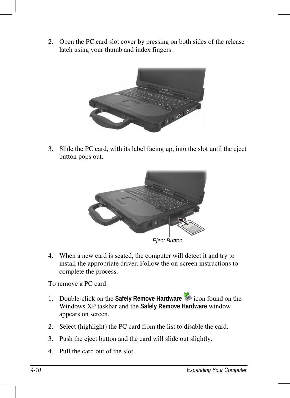
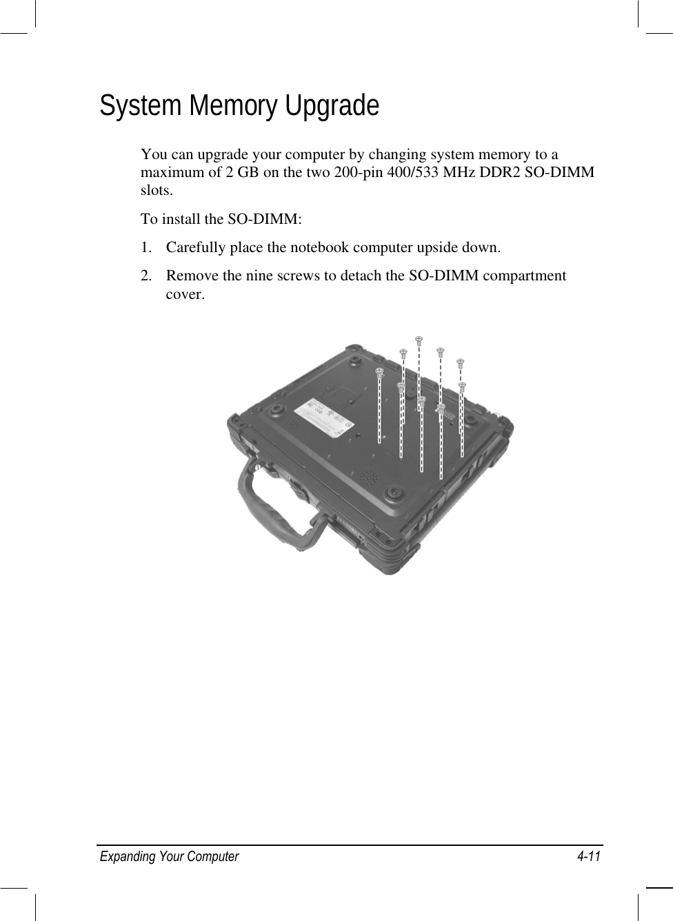
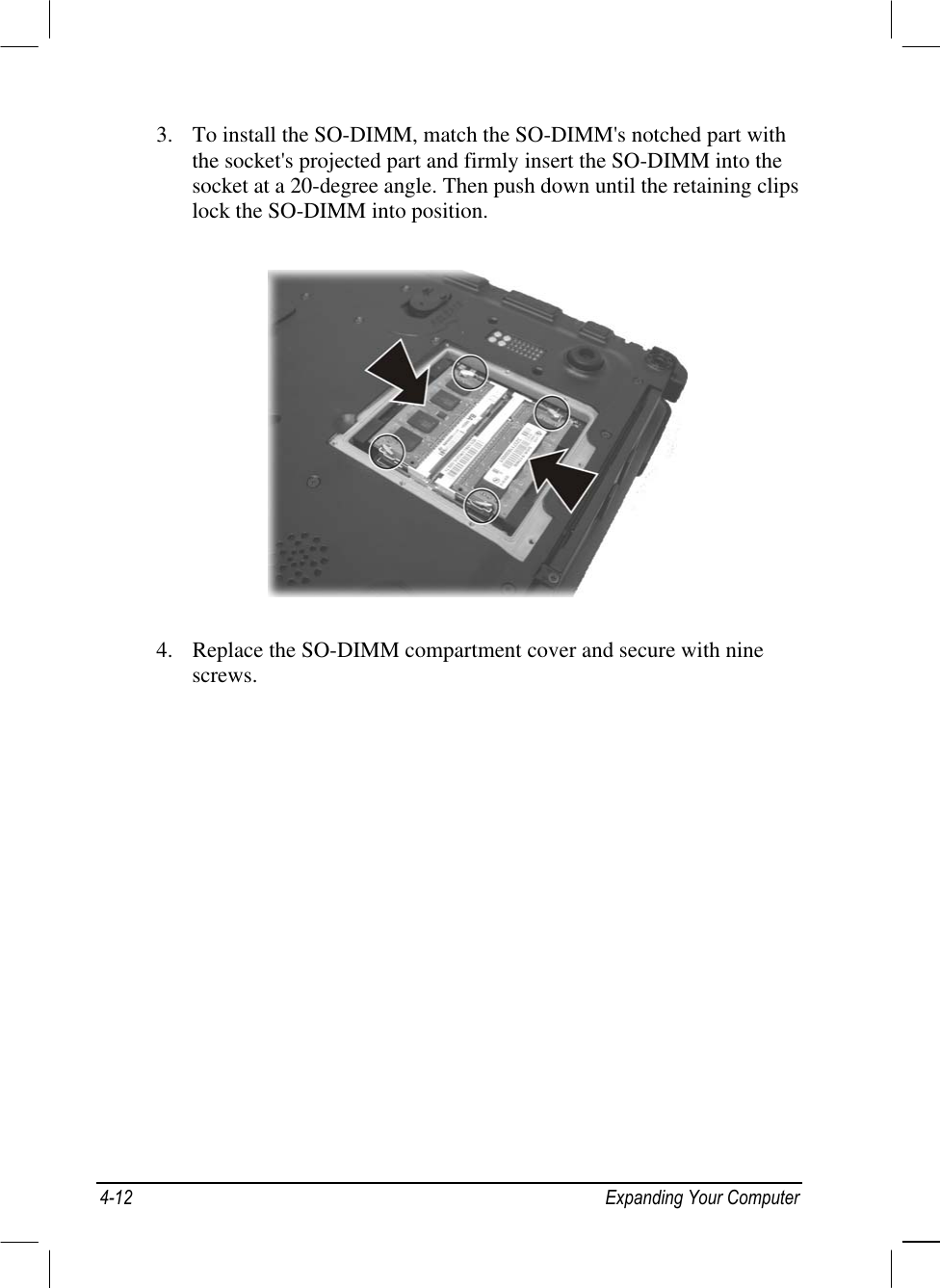
UserManual.wiki
>
Getac Technology
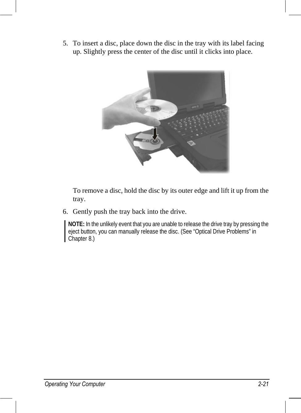
>
032 User Manual
Manual
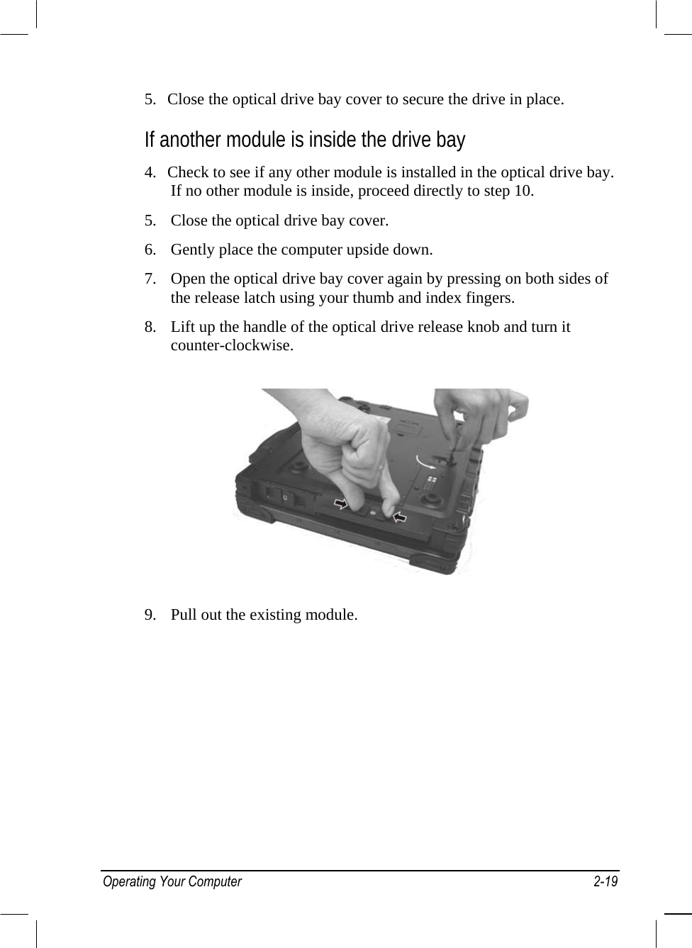
Navigation menu
Upload a User Manual
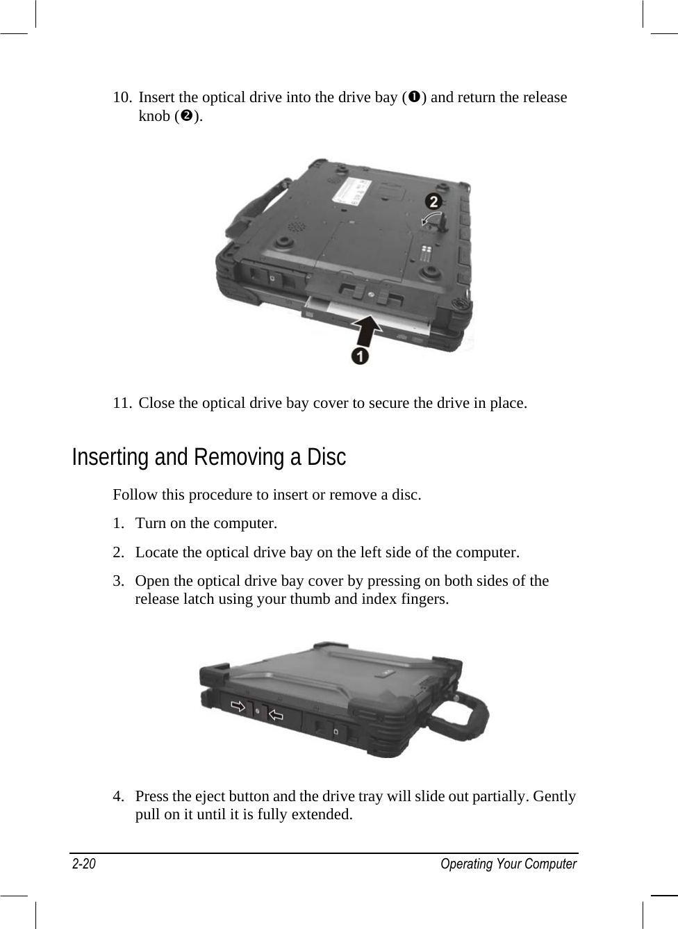
Namespaces
Wiki Guide
HTML
PDF
Info
Views
User Manual
Discussion / Help
Navigation


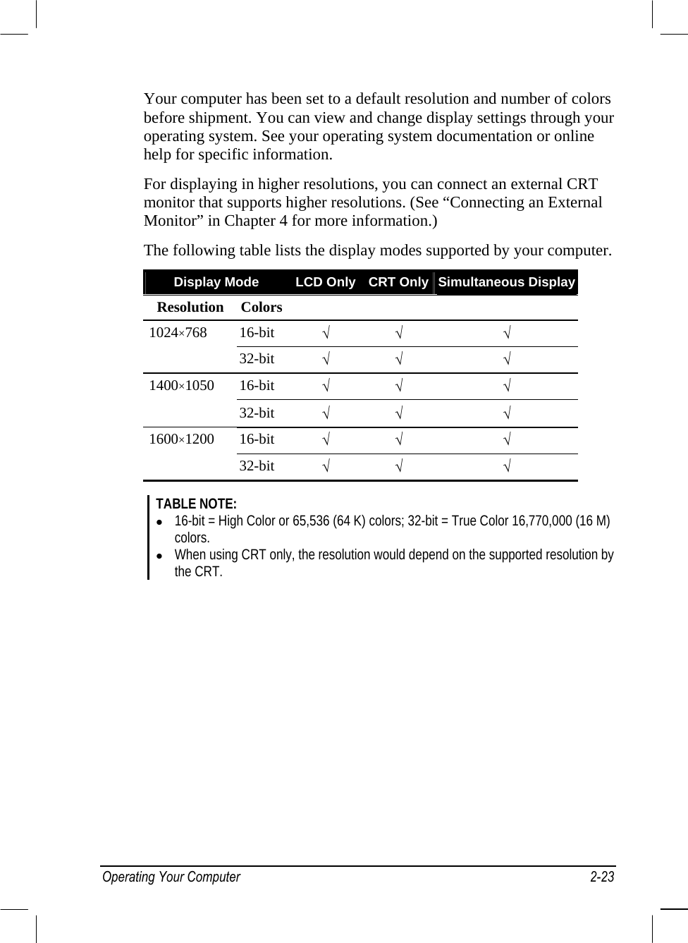
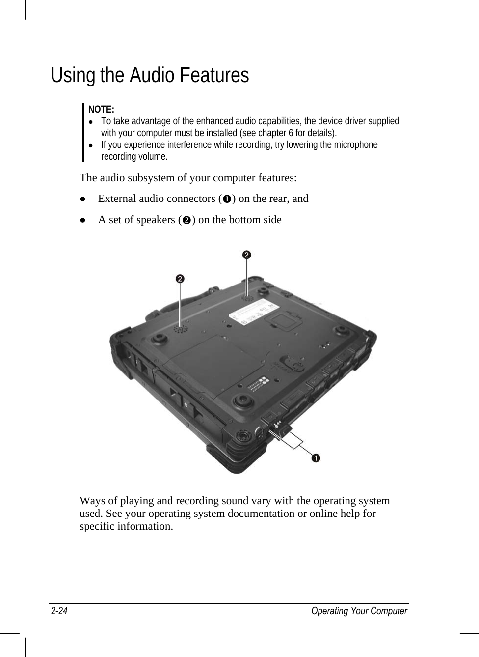
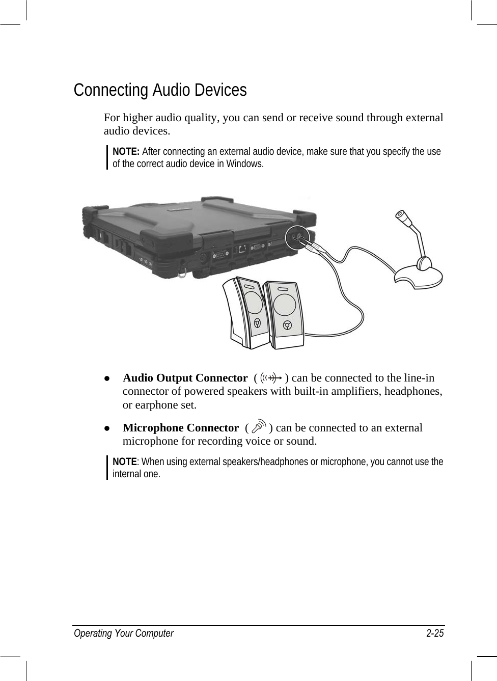
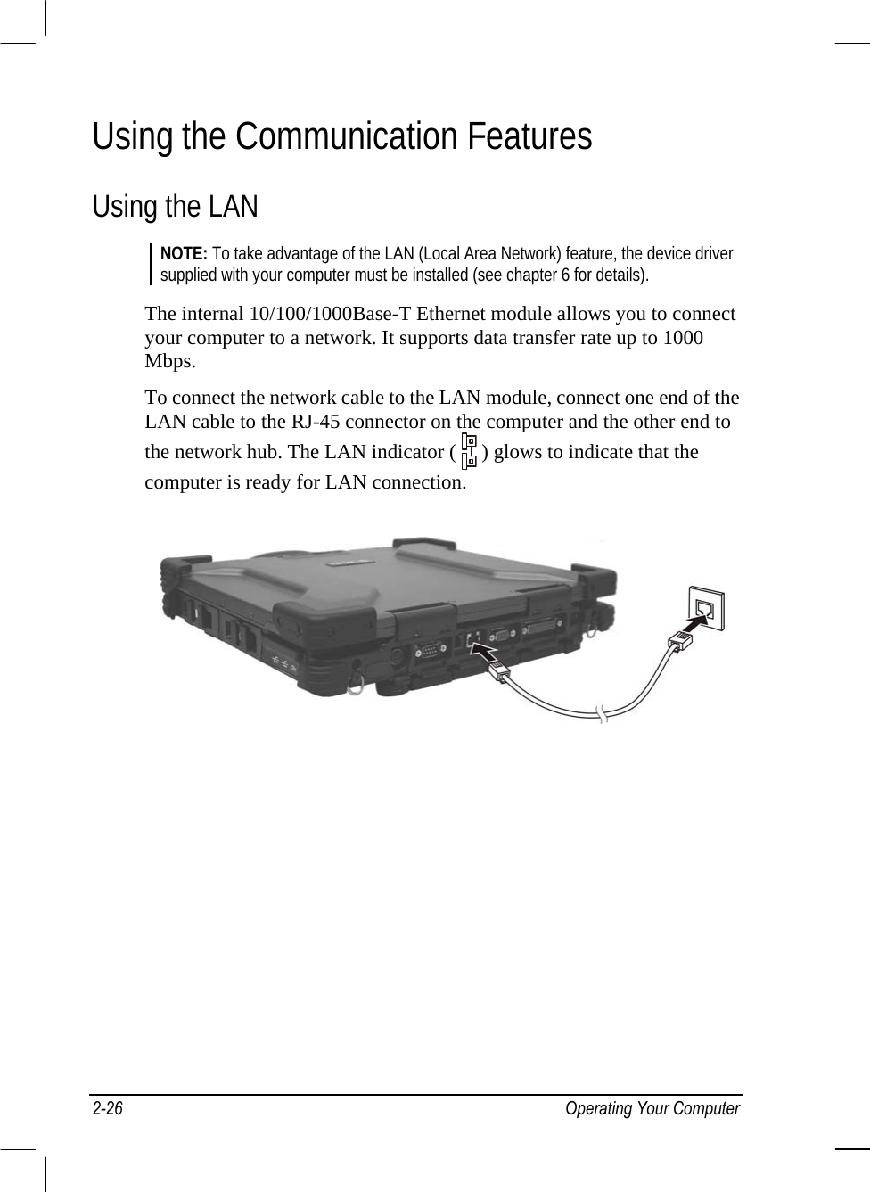


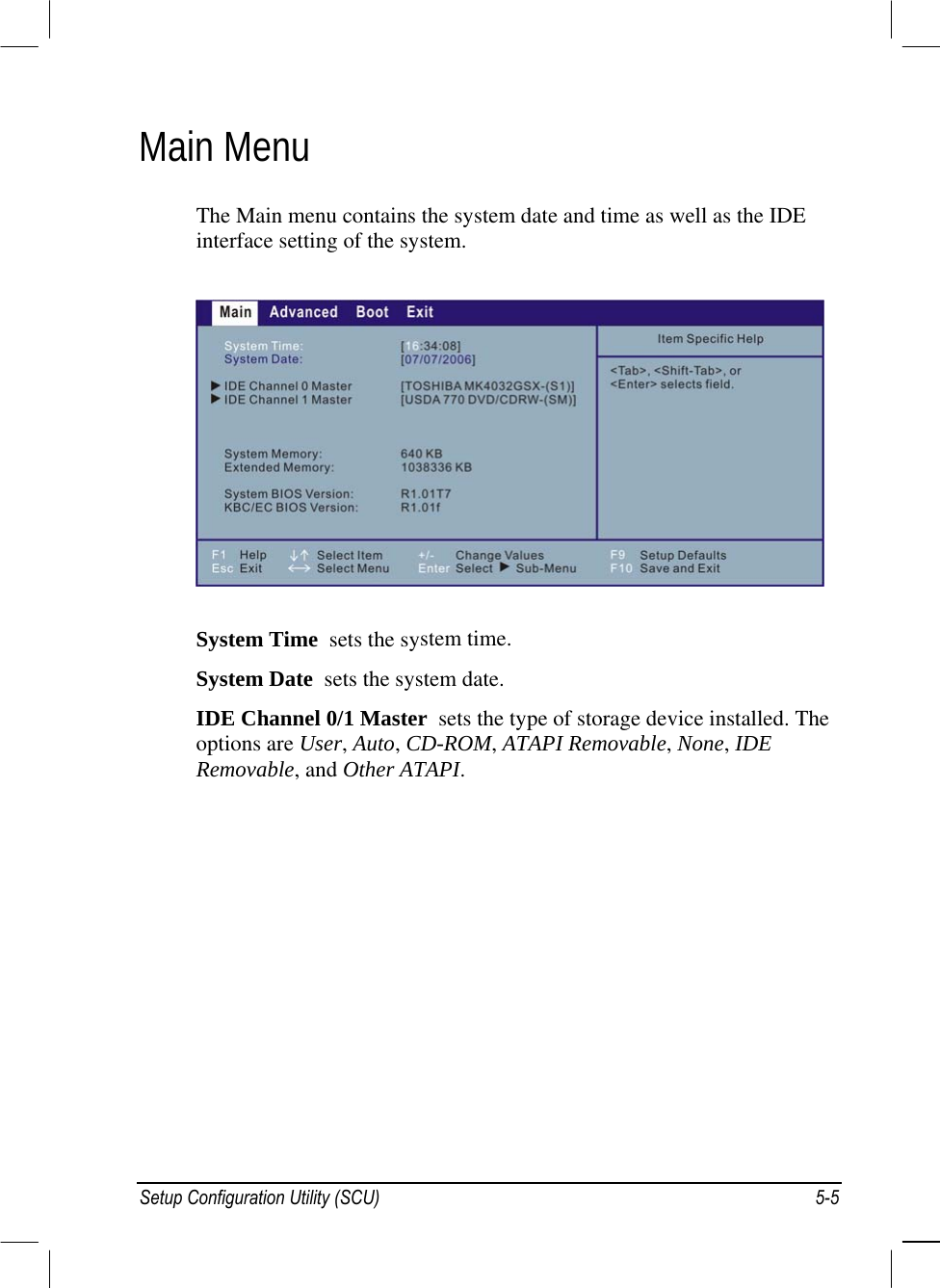


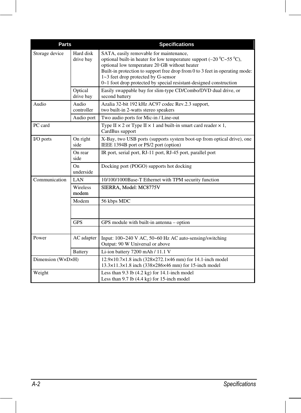
![Parts Specifications Temperature Operating: 0 °C (32 °F) to 55 °C (131 °F) – standard –20 °C (–4 °F) to 60 °C (140 °F) – option Storage: –40 °C (–40 °F) to 70 °C (158 °F) Humidity Operating: 5 % to 95 % RH, non-condensing Altitude Operating: 15,000 ft Storage: 40,000 ft Change rate: 2,000 ft/min Shock Operating: 15 g, 11 ms half sine wave Storage: 50 g, 11 ms half sine wave Vibration Operating: 10~57.5 Hz 0.075 mm, 57.5~500 Hz / 1 g (highway truck vibration exposure) Storage: 10~57.5 Hz 0.15 mm, 57.5~500 Hz 0.15 / 2 g (general minimum integrity exposure] Drop Survives 3 ft drop on steel plate, 4 ft drop on plywood 26 times (LCD panel closed and powered-off) Environment ESD (electrostatic discharge Air discharge: 0~8 KV (included) no error 8~15 KV allow soft error Contact discharge: 0~6 KV (included) no error 6~8 KV allow soft error Specifications A-3](https://usermanual.wiki/Getac-Technology/032/User-Guide-939664-Page-132.png)