Getac Technology 033 CDMA800, 1900 Notebook Computer User Manual Manual 2
Getac Technology Corp. CDMA800, 1900 Notebook Computer Manual 2
Contents
- 1. Manual 3
- 2. Manual 2
- 3. Manual 1
Manual 2

M230
Operation Manual
Part Number: 7990011600010000 0000 0001 R00
(August 2006)

TRADEMARKS
All brand and product names are trademarks or registered trademarks of their
respective companies.
NOTE
The information in this manual is subject to change without notice.

Table of Contents
Preface......................................................................................vii
Chapter 1 Getting Started.....................................................1-1
Getting the Computer Running................................................1-2
Unpacking..........................................................................1-2
Connecting to AC Power ...................................................1-2
Opening the Cover.............................................................1-4
Powering the Computer .....................................................1-5
Taking a Look at the Computer...............................................1-6
Right-Side Components.....................................................1-6
Left-Side Components .......................................................1-7
Rear Components...............................................................1-8
Front Components..............................................................1-9
Bottom-Side Components................................................1-11
Top-open Components.....................................................1-13
Where to Go from Here.........................................................1-15
Chapter 2 Operating Your Computer...................................2-1
Starting and Stopping the Computer........................................2-2
Starting the Computer........................................................2-2
Stopping the Computer ......................................................2-2
Using the Keyboard.................................................................2-4
Typewriter Keys.................................................................2-4
Cursor-Control Keys..........................................................2-5
Numeric Keypad ................................................................2-5
Euro Symbol ......................................................................2-6
i

Windows Keys ...................................................................2-6
Function Keys ....................................................................2-6
Fn Key................................................................................2-7
Hot Keys ............................................................................2-7
Using the Touchpad.................................................................2-9
Configuring the Touchpad ...............................................2-11
Using the Touchscreen (Optional).........................................2-12
Using the Hard Disk Drive ....................................................2-14
Replacing the Hard Disk Drive........................................2-14
Using the Optical Drive.........................................................2-17
Installing the Optical Drive..............................................2-18
Inserting and Removing a Disc........................................2-20
Using the Video Features.......................................................2-22
Configuring the Display Modes.......................................2-22
Using the Audio Features ......................................................2-24
Connecting Audio Devices ..............................................2-25
Using the Communication Features.......................................2-26
Using the LAN.................................................................2-26
Using the Wireless LAN (WLAN)...................................2-27
Using the Modem.............................................................2-30
Using the Wireless Modem (Optional) ............................2-31
Using the GPS (Optional) ................................................2-32
Using Bluetooth (Optional)..............................................2-32
Chapter 3 Managing Power ..................................................3-1
AC Adapter..............................................................................3-2
Battery Pack.............................................................................3-3
Charging the Battery Pack .................................................3-3
Initializing the Battery Pack...............................................3-4
Checking the Battery Level................................................3-4
Replacing the Primary Battery Pack ..................................3-5
Installing the Secondary Battery Pack ...............................3-6
Battery Low Signals and Actions.......................................3-7
Power Management .................................................................3-9
Hibernation.......................................................................3-10
ii

Power-Saving Tips ................................................................3-11
Chapter 4 Expanding Your Computer..................................4-1
Connecting an External Monitor .............................................4-2
Connecting a USB Device.......................................................4-3
Connecting a Parallel Device...................................................4-4
Connecting a Serial Device .....................................................4-5
Connecting an IR Device.........................................................4-6
Connecting an IEEE 1394B Device ........................................4-8
Using PC Cards .......................................................................4-9
PC Card Type.....................................................................4-9
CardBus Support................................................................4-9
Inserting and Removing a PC Card....................................4-9
System Memory Upgrade......................................................4-11
Chapter 5 Setup Configuration Utility (SCU).......................5-1
When and How to Use the SCU Program................................5-2
When to Use.......................................................................5-2
Starting SCU......................................................................5-2
Moving Around and Making Selections............................5-4
Main Menu ..............................................................................5-5
Advanced Menu.......................................................................5-6
Boot Menu...............................................................................5-8
Exit Menu ................................................................................5-9
Chapter 6 Installing Software Drivers..................................6-1
How to Use the Driver CD ......................................................6-2
Touchscreen Driver............................................................6-8
Using the OSD.......................................................................6-10
Chapter 7 Caring for the Computer......................................7-1
Protecting the Computer..........................................................7-2
Using the Password............................................................7-2
Using the Cable Lock.........................................................7-2
Using an Anti-Virus Strategy.............................................7-3
Taking Care of the Computer ..................................................7-4
iii

Location Guidelines ...........................................................7-4
General Guidelines.............................................................7-4
Cleaning Guidelines...........................................................7-5
Battery Pack Guidelines.....................................................7-5
When Traveling .......................................................................7-6
Chapter 8 Troubleshooting...................................................8-1
Preliminary Checklist ..............................................................8-2
Solving Common Problems.....................................................8-3
Battery Problems................................................................8-4
Bluetooth Problems............................................................8-4
Optical Drive Problems......................................................8-5
Display Problems ...............................................................8-6
Hardware Device Problems................................................8-7
Hard Disk Drive Problems.................................................8-7
Infrared Problems...............................................................8-8
Keyboard, Mouse and Touchpad Problems .......................8-8
LAN Problems ...................................................................8-9
WLAN Problems................................................................8-9
Modem Problems .............................................................8-11
PC Card Problems............................................................8-11
Power Management Problems..........................................8-11
Printer Problems...............................................................8-12
Software Problems ...........................................................8-13
Sound Problems ...............................................................8-13
Startup Problems..............................................................8-14
Other Problems.................................................................8-15
Resetting the Computer .........................................................8-16
Appendix A Specifications.................................................... A-1
Appendix B Regulatory Information..................................... B-1
On the Use of the System .......................................................B-2
Class B Regulations ..........................................................B-2
Safety Notices ...................................................................B-3
On the Use of RF Device........................................................B-6
iv

USA and Canada Safety Requirements and Notices......... B-6
European Union CE Marking and Compliance Notices ... B-9
v

Preface
This manual contains information that will help you operate the
computer. It is divided into 8 chapters and 2 appendices.
Chapter 1, Getting Started, takes you through the process of setting
up the computer and identifying its external components.
Chapter 2, Operating Your Computer, tells you how to use the
computer’s components and features.
Chapter 3, Managing Power, provides information on power.
Chapter 4, Expanding Your Computer, provides information on
installing and using peripheral devices.
Chapter 5, Using BIOS Setup, describes the SCU program that
configures the computer’s BIOS settings.
Chapter 6, Installing Software Drivers, describes how to install the
drivers and utilities supplied with the computer.
Chapter 7, Caring for the Computer, gives you tips in care and
maintenance.
Chapter 8, Troubleshooting, gives solutions to common problems
you may encounter when using the computer.
Appendix A, Specifications, gives a brief specification of the
computer.
Appendix B, Regulatory Information, provides regulatory
statements and safety notices on your computer.
vii

Notational Conventions
Throughout this manual, the following conventions are used to
distinguish elements of text.
NOTE: identifies additional information that requires special attention.
CAUTION: identifies important information that, if not followed, may result in loss of
data or damage to the computer.
Keyboard keys are shown in a bold typeset. For example:
Press Enter to complete.
When keys are joined by a plus sign (+), press the first key, and, while
keeping the first key down, press the remaining keys, finally release all
the keys. When necessary, keys are also shown in graphics.
A title, command, setup item, or button that you can see on the screen is
shown in boldface. A value or an option that you can select for a setup
item is shown in italic. For example:
Select Power Schemes, set it to Portable/Laptop, and then click
the OK button.
viii

CHAPTER 1
Getting Started
Congratulations on purchasing this computer.
This high performance notebook computer is especially designed for the
practical applications of warehouses, automobiles, vehicles, public
security, repairing, assisting the handicapped, and other demanding
situations where conventional notebook computers just cannot measure
up.
This chapter first tells you step by step how to get the computer up and
running. You will find instructions for these procedures:
Unpacking
Connecting to AC power
Opening the cover
Turning on the computer
Turning off the computer
Then, you will find a section briefly introducing the external components
of the computer. And the last section navigates you to the information
you may need after the computer is ready for use.

Getting the Computer Running
This section guides you through the procedures for getting the computer
ready for operation.
Unpacking
After unpacking the shipping carton, you should find these standard
items:
Notebook computer
Accessories:
− AC adapter (100~240 VAC, 50/60 Hz)
− AC power cord (US/CE/UK/SA)
− Car adapter (option)
− Extra battery pack (option)
− Touchscreen pen (option)
− Driver CD
− This Operation Manual
− Vehicle docking (option)
− Office docking (option)
− Carrying bag (option)
Inspect all the items. If any item is damaged or missing, notify your
dealer immediately.
Keep the shipping carton and packing materials in case you need to ship
or store the computer in the future.
Connecting to AC Power
The computer operates either on the external AC power or internal
battery power. It is suggested that you use AC power when you start up
the computer for the first time.
CAUTION: Use only the AC adapter included with your computer. Using other AC
adapters may damage the computer.
1-2 Getting Started
NOTE:
Power Supply Cord: (optional) Detachable, minimum 1.5 m long. Listed, rated
minimum 125 V, 7 A, having a 2/18 AWG, type SVT flexible cord. One end terminates
with a parallel blade, molded-on, attachments plug with a 7 A, 125 V (NEMA 1-15P)
configuration; other end terminates with a molded-on appliance coupler.
Alternative: (optional) Detachable, maximum 4.5 m (14.76 ft) long. Listed, rated
minimum 250 V, 6 A, having a 3/18 AWG, type SVT flexible cord. One end terminates
with a Tandem blade, grounding, listed molded-on, attachments plug with a 6 A, 250 V
(NEMA 6-15P) configuration; other end terminates with a molded-on appliance
coupler.
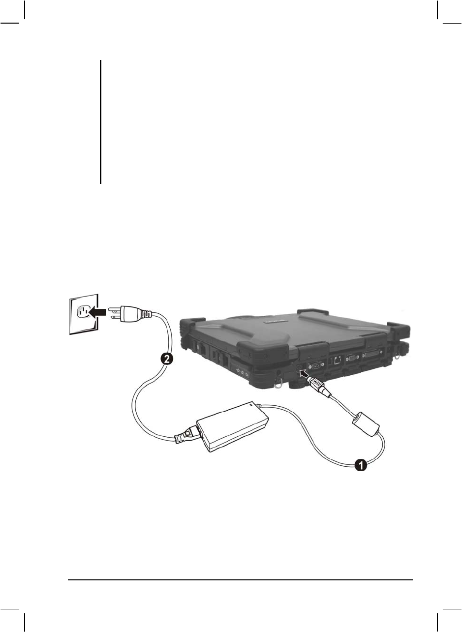
1. Make sure the computer is turned off.
2. Plug the DC cord of the AC adapter to the power connector on the
rear side of the computer () .
3. Plug the female end of the AC power cord to the AC adapter and the
male end to an electrical outlet () .
4. When the AC adapter is connected, the indicator on the AC adapter
lights up, indicating that power is being supplied from the electrical
outlet to the AC adapter and onto your computer. Now, you are ready
to turn on the computer.
Getting Started 1-3
CAUTION:
When you disconnect the AC adapter, disconnect from the electrical outlet first and
then from the computer. A reverse procedure may damage the AC adapter or the
computer.
When unplugging the connector, always hold the plug head. Never pull on the cord.
NOTE: When the AC adapter is connected, it also charges the battery pack. For
information on using battery power, see Chapter 3.
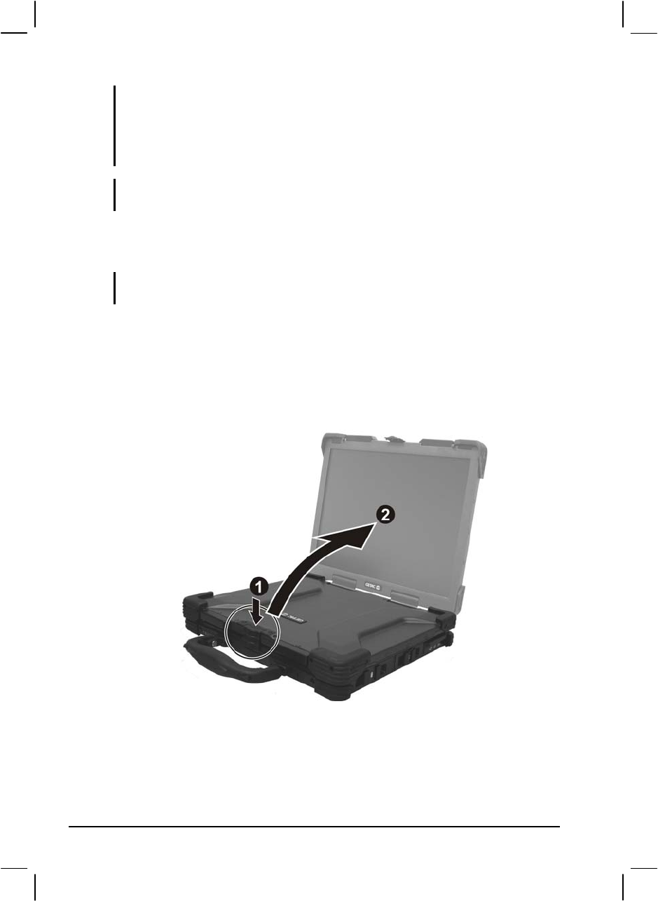
Opening the Cover
CAUTION: Be gentle when opening and closing the cover. Opening it vigorously or
slamming it shut could damage the computer.
1. Open the top cover by pushing on the top portion of the cover latch,
and then pulling on the bottom portion of the cover latch.
2. Lift up the cover. You can tilt the cover forward or backward for
optimal viewing clarity.
1-4 Getting Started
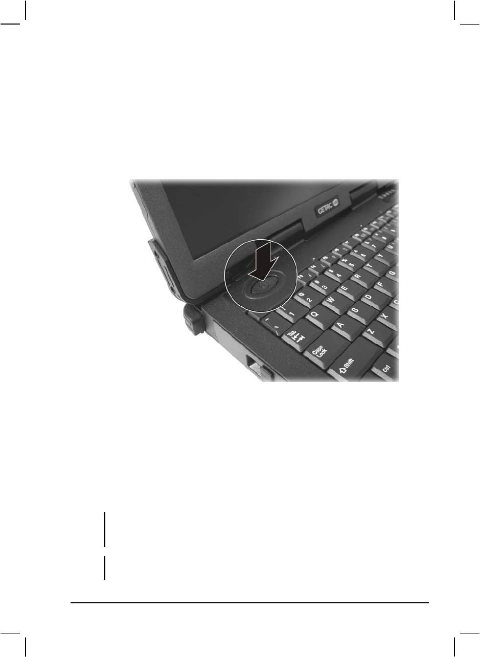
Powering the Computer
Turning On
1. Make sure the computer is connected to AC power.
2. Press the power button.
3. Each time the computer is turned on, it performs a Power-On Self
Test (POST), and the operating system such as Windows should
start.
Turning Off
To turn off the computer power, use the “Shut Down” command of your
operating system.
NOTE: There are other ways you can stop the computer so that you will be back to
where you left off when you next turn on the computer. (See “Stopping the Computer”
in Chapter 2 for information.)
CAUTION: If you have to turn the computer on again immediately after turning it off,
wait for at least five seconds. Turning the computer off and on rapidly can damage it.
Getting Started 1-5

Taking a Look at the Computer
This section identifies the external components of the computer and
briefly describes the function of each component.
NOTE: Depending on the model you purchased, the appearance of your computer may
not exactly be the same as those shown in this manual.
Right-Side Components
Ref Component Description See Also
Primary
Battery Pack Supplies power to your computer when external
power is not connected. P. 3-5
PC Card Slot Accepts a PC card for additional functions. P. 4-10
USB Ports Each of the two ports connects a USB device,
such as a USB floppy drive, USB disk, printer,
digital camera, joystick, and more.
P. 4-3
PS/2 Port Connects a PS/2 keyboard and/or mouse. P. 4-4
1-6 Getting Started
Left-Side Components
Ref Component Description See Also
CD/Combo/
DVD Dual
Drive
Accepts a compact disc (CD) for installing or
loading software, accessing data, and playing
music/video.
P. 2-17
Secondary
Battery Pack You can purchase a secondary battery pack that
supplies power to your computer when external
power is not connected.
P. 3-6
Hard Disk
Drive Slot Inside is the hard disk drive of your computer. P. 2-14
Getting Started 1-7
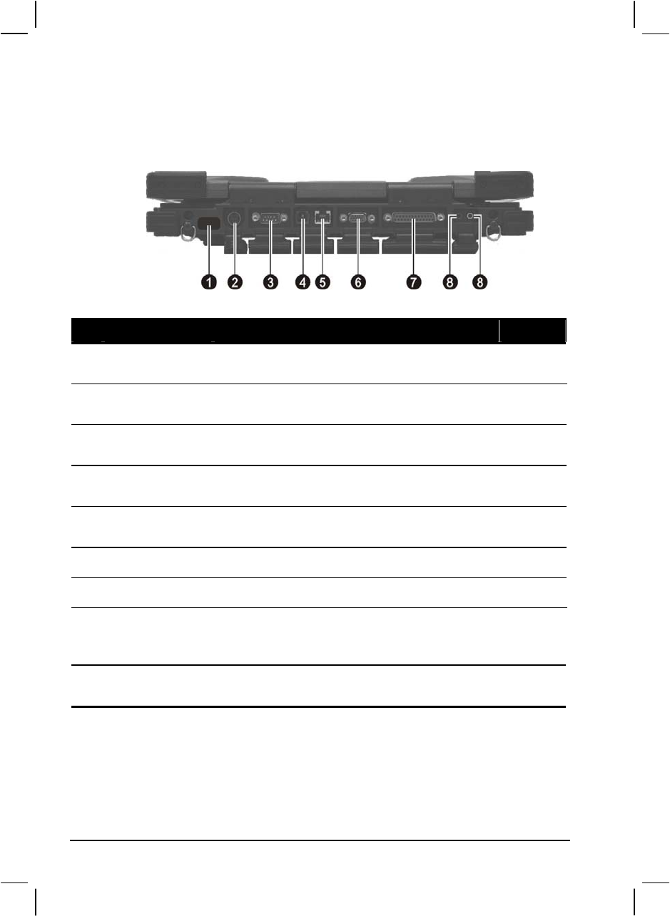
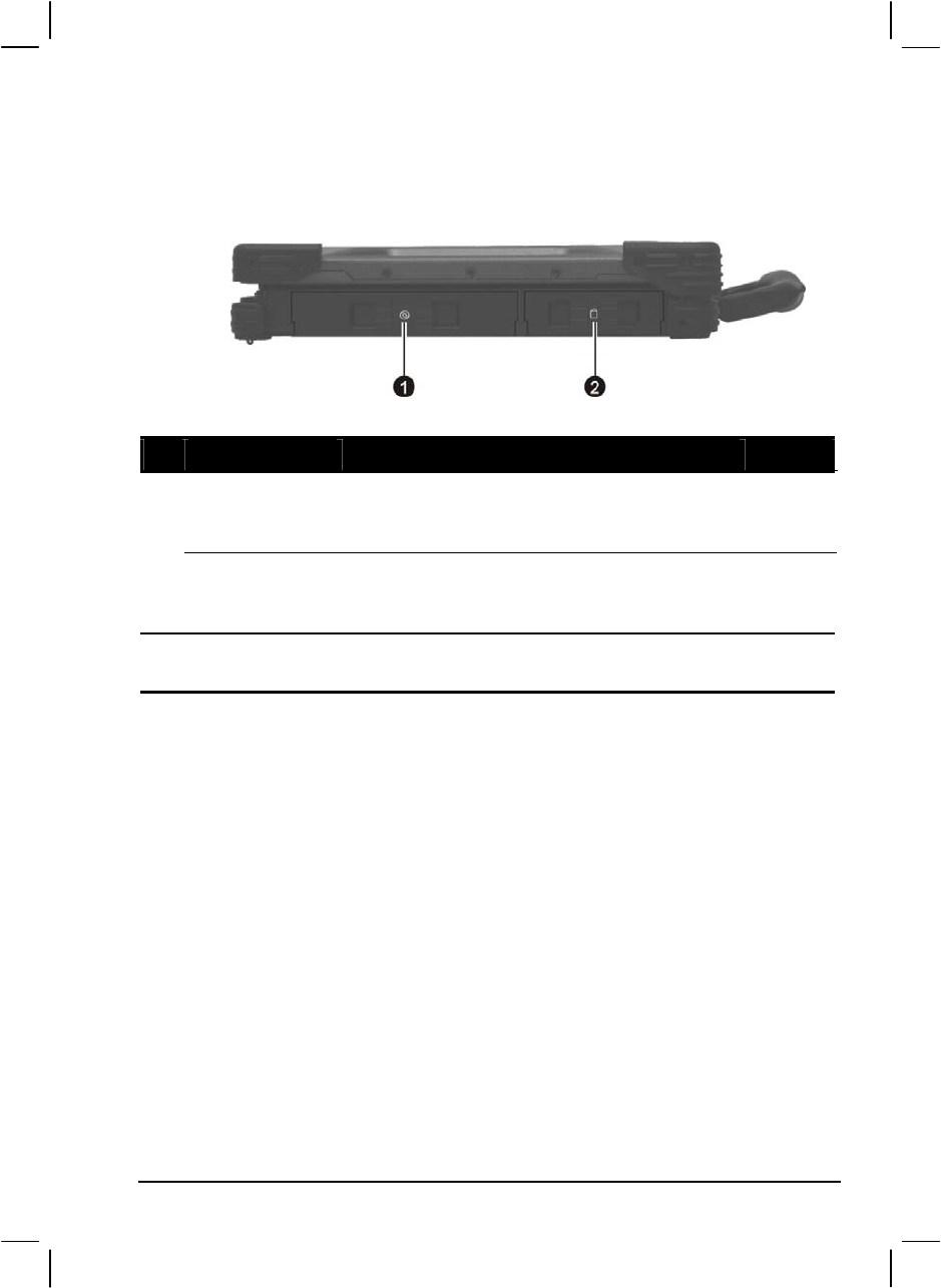
Rear Components
Ref Component Description See Also
IR Port Connects an IrDA-compliant device for wireless
data transfer. P. 4-7
Power
Connector Connects the AC adapter. P. 1-3
Serial Port Connects a serial device, such as an external
modem. P. 4-6
RJ-11
Connector Connects the telephone line. P. 2-29
RJ-45
Connector Connects the LAN cable. P. 2-25
VGA Port Connects an external monitor. P. 4-2
Parallel Port Connects a parallel device, such as a printer. P. 4-5
Audio Output
Connector Connects a set of headphones, external speakers
with amplifier, an audio recording device for
audio output.
P. 2-24
Microphone
Connector Connects an external microphone. P. 2-24
1-8 Getting Started
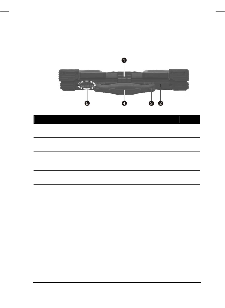
Front Components
Ref Component Description See Also
Top Cover
Latch Locks the top cover. P. 1-4
Kensington
Lock Locks the computer to a stationary object for
security. P. 7-2
Touchscreen
Pen (option) Provides a convenient way to use the
touchscreen. Can be stretched for better grip and
handling.
P. 2-12
Handle Allows you to carry your computer for an easy
grip.
Getting Started 1-9
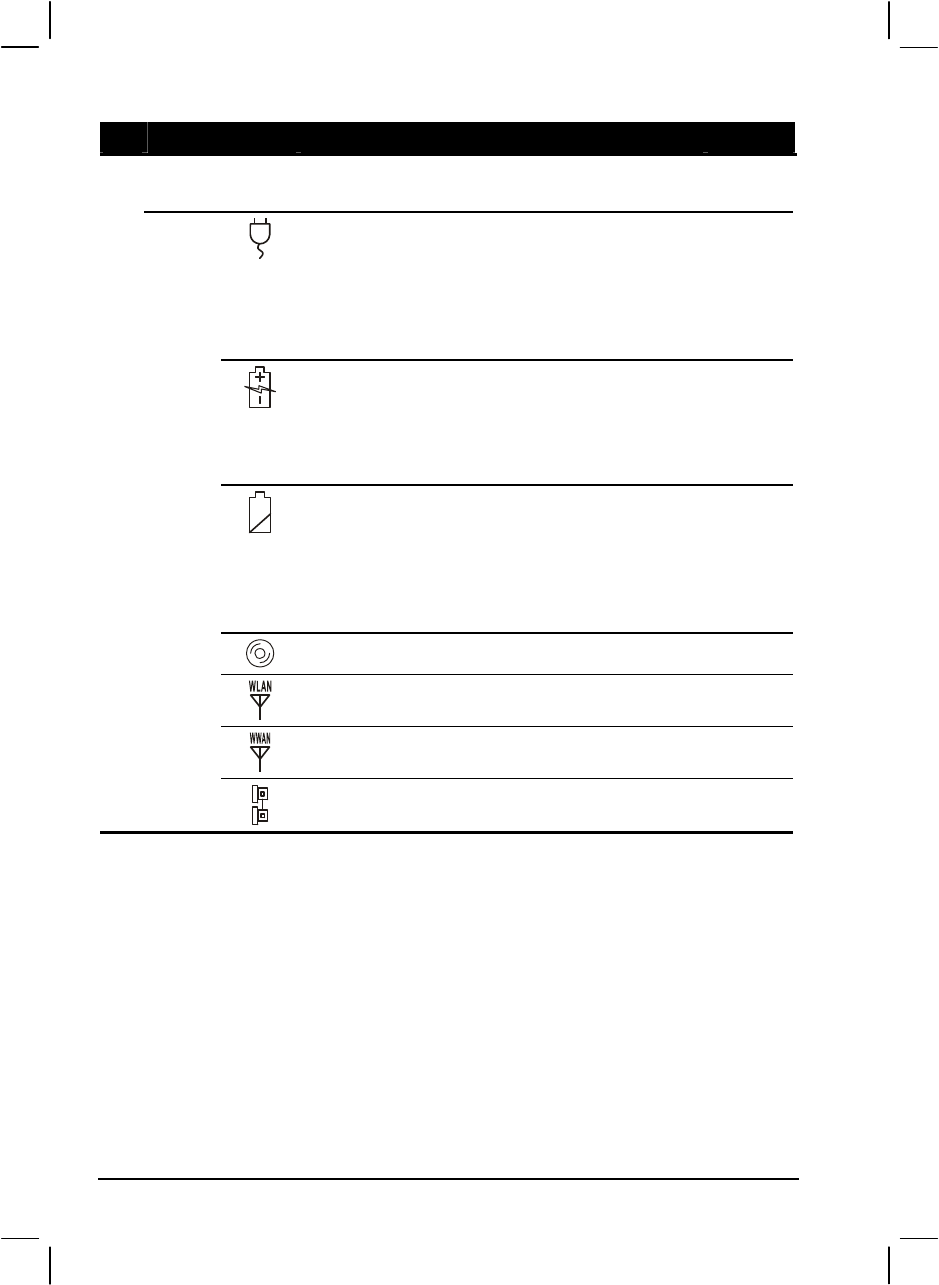
Ref Component Description See Also
Device
Indicators Show the current status of the computer’s
devices.
AC power indicator.
Glows green when the computer is using AC
power.
Glows red when the computer, using AC power,
is in Standby mode.
P. 3-2
Battery Charge Indicator
Glows green when the battery is fully charged
and connected to AC power.
Glows amber when the battery is being charged.
P. 3-3
Battery Power Indicator
Glows green when the computer is using battery
power.
Blinks amber when the battery is almost
completely discharged.
P. 3-7
CD/Combo/DVD Dual drive in-use indicator P. 2-17
Wireless LAN (Local Area Network) indicator P. 2-27
Wireless modem indicator P. 2-30
Wired LAN indicator P. 2-25
1-10 Getting Started
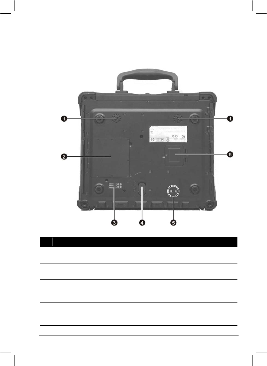
Bottom-Side Components
Ref Component Description See Also
Stereo Speaker
Set Sends out sound and voice from the computer. P. 2-20
Memory Slot Contains the memory slot for expanding the
memory size of your computer. P. 4-12
Docking
Connector
(POGO)
For connecting to a Port Replicator / car mount
(both are available as an option).
Release Knob Allows you to remove the CD/Combo/DVD Dual
drive as well as eject the secondary battery pack
(option).
P. 2-14
P. 3-6
Getting Started 1-11

Ref Component Description See Also
??? ???
SIM Card Slot Contains the SIM card slot for using the GPS
function. P. 2-26
1-12 Getting Started
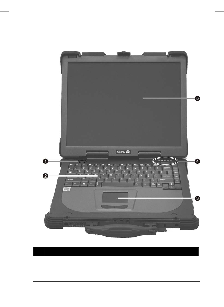
Top-open Components
Ref Component Description See Also
Power Button Turns the computer power ON and OFF. P. 1-5
Getting Started 1-13

Ref Component Description See Also
Keyboard Serves as the data input device of the computer. P. 2-4
Touchpad Serves as the pointing device of the computer. P. 2-9
Device
Indicators Show the current status of the computer’s
devices.
Power On Indicator
Glows green when the computer is on.
Glows red when the computer is in Standby
mode.
P. 1-5
Hard Disk Drive Indicator
Blinks green when the hard disk drive is active.
Blinks red when the hard disk heater is on.
P. 2-14
Scroll Lock indicator P. 2-4
Num Lock indicator P. 2-4
Caps Lock indicator P. 2-4
LCD Screen Displays the output of the computer.
Can also have the optional touchscreen
function.
P. 2-21
P. 2-12
1-14 Getting Started

Where to Go from Here
As your computer is ready for operation, you may want to do any of the
following now:
For this purpose… Do this…
To know more about the computer… Go on to the next chapter.
To install the operating system if your
dealer has not already done so… See the operating system manual.
To know more about the operating
system… Read the operating system manual.
To install the drivers if your dealer has
not already done so… See Chapter 6.
To charge the battery pack for the first
time… See “Charging the Battery Pack” in
Chapter 3.
Getting Started 1-15

1-16 Getting Started

CHAPTER 2
Operating Your Computer
This chapter provides information about the use of the computer.
If you are new to computers, reading this chapter will help you learn the
operating basics. If you are already a computer user but are new to
notebook computers, you may choose to read only the parts containing
information unique to your computer.
Described in this chapter are the operating basics of these components:
Keyboard
Touchpad
Touchscreen
Hard disk drive
Optical drive
And these features:
Starting and stopping the computer
Video features
Audio features
Communication features

Starting and Stopping the Computer
There are a number of ways to start and stop the computer.
Starting the Computer
You always start the computer using the power button.
A computer starts up with an operating system (OS) existing on the
storage device such as the hard disk; or from a CD disc if you have the
respective modules installed. The computer will automatically load the
OS after you turn it on. This process is called booting.
NOTE: An operating system is the platform for all your software application programs to
run on. The most widely used operating system today is Microsoft Windows.
Stopping the Computer
When you finish a working session, you can stop the computer by turning
off the power or leaving the computer in Standby or Hibernation mode:
To stop in
this mode… Do this… To start up or
resume again
Off Follow the shutdown procedure of your
operating system. This can prevent loss of
unsaved data or damage to your software
programs.
If the system is locked up because of
hardware or software problems, press the
power button at least 4 seconds to turn off
the computer.
Press the power
button.
Standby Depending on your settings in Windows,
you can place the computer in Standby
mode by:
• Closing the display cover
• Pressing Fn+F10
• Pressing the power button
Press any key.
2-2 Operating Your Computer

To stop in
this mode… Do this… To start up or
resume again
Hibernation Depending on your settings in Windows,
you can place the computer in
Hibernation mode by:
• Closing the display cover
• Pressing Fn+F10
• Pressing the power button
Press the power
button.
If you choose to stop in Standby or Hibernation mode, you can return to
where you left off the next time you start up the computer. (See “Power
Management” in Chapter 3 for more information.)
Operating Your Computer 2-3

Using the Keyboard
NOTE: Your computer features backlight for your keyboard to help you see the
keyboard keys during poor lighting conditions. Press Fn+F1 to turn it on/off (see Hot
Keys later in this chapter).
Your keyboard has all the standard functions of a full-sized computer
keyboard plus a Fn key added for specific functions.
The standard functions of the keyboard can be further divided into four
major categories:
Typewriter keys
Cursor-control keys
Numeric keys
Function keys
Typewriter Keys
Typewriter keys are similar to the keys on a typewriter. Several keys are
added such as the Ctrl, Alt, Esc, and lock keys for special purposes. When
the lock keys (Caps Lock, Num Lk, and Scroll Lk) are pressed, their
corresponding indicators light up.
The Control/Alternate key is normally used in combination with other
keys for program-specific functions. The Escape key is usually used for
stopping a process. Examples are exiting a program and canceling a
command. The function depends on the program you are using.
2-4 Operating Your Computer
Cursor-Control Keys
NOTE: The word “cursor” refers to the indicator on the screen that lets you know
exactly where on your screen anything you type will appear. It can take the form of a
vertical or horizontal line, a block, or one of many other shapes.
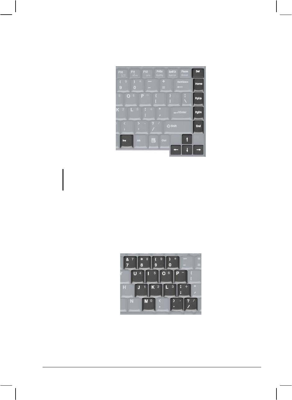
Numeric Keypad
A 15-key numeric keypad is embedded in the typewriter keys as shown
next:
Numeric keys facilitate entering of numbers and calculations. When Num
Lock is on, the numeric keys are activated; meaning you can use these
keys to enter numerals.
Operating Your Computer 2-5
NOTE:
When the numeric keypad is activated and you need to type the English letter in the
keypad area, you can turn Num Lock off or you can press Fn and then the letter
without turning Num Lock off.
Some software may not be able to use the numeric keypad on the computer. If so,
use the numeric keypad on an external keyboard instead.
Euro Symbol
You can press the Euro dollar sign on the keyboard.
To press the Euro sign on the keyboard, hold down either of the Alt
keys and type 0128 on the numeric keypad of your keyboard.
To press the Euro sign on an UK keyboard, hold down the Alt Gr key
and press 4 (which has an Euro sign on it).
Windows Keys
The keyboard has two keys that perform Windows-specific functions:
Windows Logo key and Application key.
The Windows Logo key opens the Start menu and performs
software-specific functions when used in combination with other keys.
The Application key usually has the same effect as a right mouse
click. (See your Windows manual for more information.)
Function Keys
On the top row of the keys are the function keys: F1 to F12. Function keys
are multi-purpose keys that perform functions defined by individual
programs.
2-6 Operating Your Computer

Fn Key
The Fn key, at the lower left corner of the keyboard, is used with another
key to perform the alternative function of a key. The letter “Fn” and the
alternative functions are identified by the color of blue on the keytop. To
perform a desired function, first press and hold Fn, then press the other
key.
Hot Keys
Hot keys refer to a combination of keys that can be pressed any time to
activate special functions of the computer. Most hot keys operate in a
cyclic way. Each time a hot key combination is pressed, it shifts the
corresponding function to the other or next choice.
You can easily identify the hot keys with the icons imprinted on the
keytop. The hot keys are described next.
Key Description
Switches the optional keyboard backlight function on/off with
10 levels of brightness in-between.
Decreases the sound volume.
Increases the sound volume.
Decreases the LCD brightness.
Increases the LCD brightness.
Switches the LCD backlight on and off
Switches the LCD on and off.
Operating Your Computer 2-7
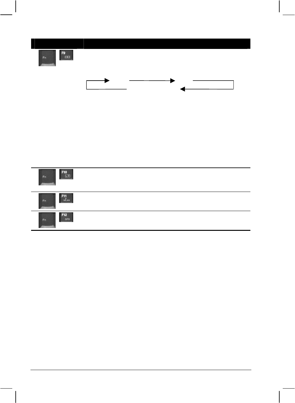
Key Description
Switches the display output to one of the following when an
external device is connected.
Upon booting the system with CRT:
LCD CRT
LCD & CRT
NOTE:
Fn+F9 will not work when playing a DVD/MPEG movie.
Using the VGA utility’s “Graphics Properties” to switch the
display output is not allowed.
Display switching when in full screen (maximize view)
DOS mode is not allowed.
If the display mode is set to 256 colors or lower, or in DOS
mode, there will be only two modes for selecting: CRT only
and LCD & CRT.
This function only applies to Plug & Play CRT monitors.
Serves as the sleep button that you can define with Windows’
Power Management. (See the “Power Management” in
Chapter 3.)
Switches the wireless LAN radio on and off.
Switches the optional GPS function on and off.
2-8 Operating Your Computer
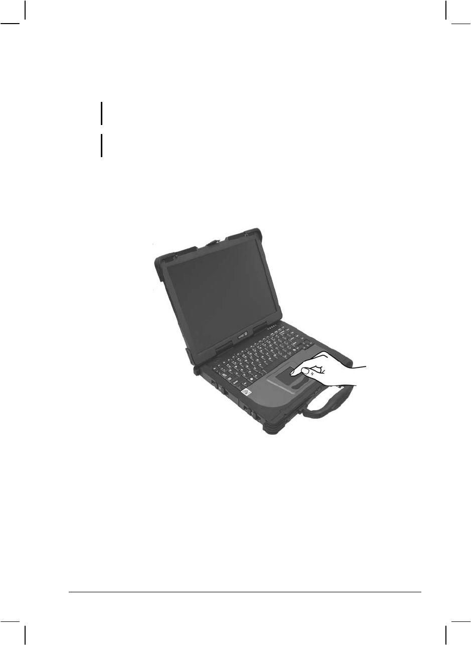
Using the Touchpad
CAUTION: Do not use a sharp object such as a pen on the touchpad. Doing so may
damage the touchpad surface.
NOTE: For optimal performance of the touchpad, keep your fingers and the pads clean
and dry. When tapping on the pad, tap lightly. Do not use excessive force.
The touchpad is a pointing device that allows you to communicate with
the computer by controlling the location of the pointer on the screen and
making selection with the buttons.
The touchpad consists of a rectangular pad and two buttons. To use the
touchpad, place your forefinger or thumb on the pad. The rectangular pad
acts like a miniature duplicate of your display. As you slide your fingertip
across the pad, the pointer (also called cursor) on the screen moves
accordingly. When your finger reaches the edge of the pad, simply
relocate yourself by lifting the finger and placing it on the other side of
the pad.
Operating Your Computer 2-9

Here are some common terms that you should know when using the
touchpad:
Term Action
Point Move your finger on the pad until the cursor points to the
selection on the screen.
Click Press and release the left button.
–or–
Tap gently anywhere on the pad.
Double-
click Press and release the left button twice in quick succession.
–or–
Tap twice on the pad rapidly.
Drag
and
drop
Press and hold the left button, then move your finger until you
reach your destination (drag). Finally, release the button (drop)
when you finish dragging your selection to the destination. The
object will drop into the new location.
–or–
Gently tap twice on the pad and on the second tap, keep your
finger in contact with the pad. Then, move your finger across the
pad to drag the selected object to your destination. When you lift
your finger from the pad, the selected object will drop into place.
Scroll To scroll is to move up and down or left and right in the working
area on the screen.
To move vertically, place your finger on the right edge of the
pad and slide your finger up and down along the edge. To move
horizontally, place your finger on the bottom edge of the pad and
slide your finger left and right.
This function works only after you install the touchpad driver
supplied with the computer and it may not work for all
applications.
TABLE NOTE: If you swap the left and right buttons, “tapping” on the touchpad
as an alternative method of pressing the left button will no longer be valid.
2-10 Operating Your Computer

Configuring the Touchpad
You may want to configure the touchpad to suit your needs. For example,
if you are a left-handed user, you can swap the two buttons so that you
can use the right button as the left button and vise versa. You can also
change the size of the on-screen pointer, the speed of the pointer, and so
on.
To configure the touchpad, you can use the standard Microsoft or IBM
PS/2 driver if you are using Windows.
Operating Your Computer 2-11
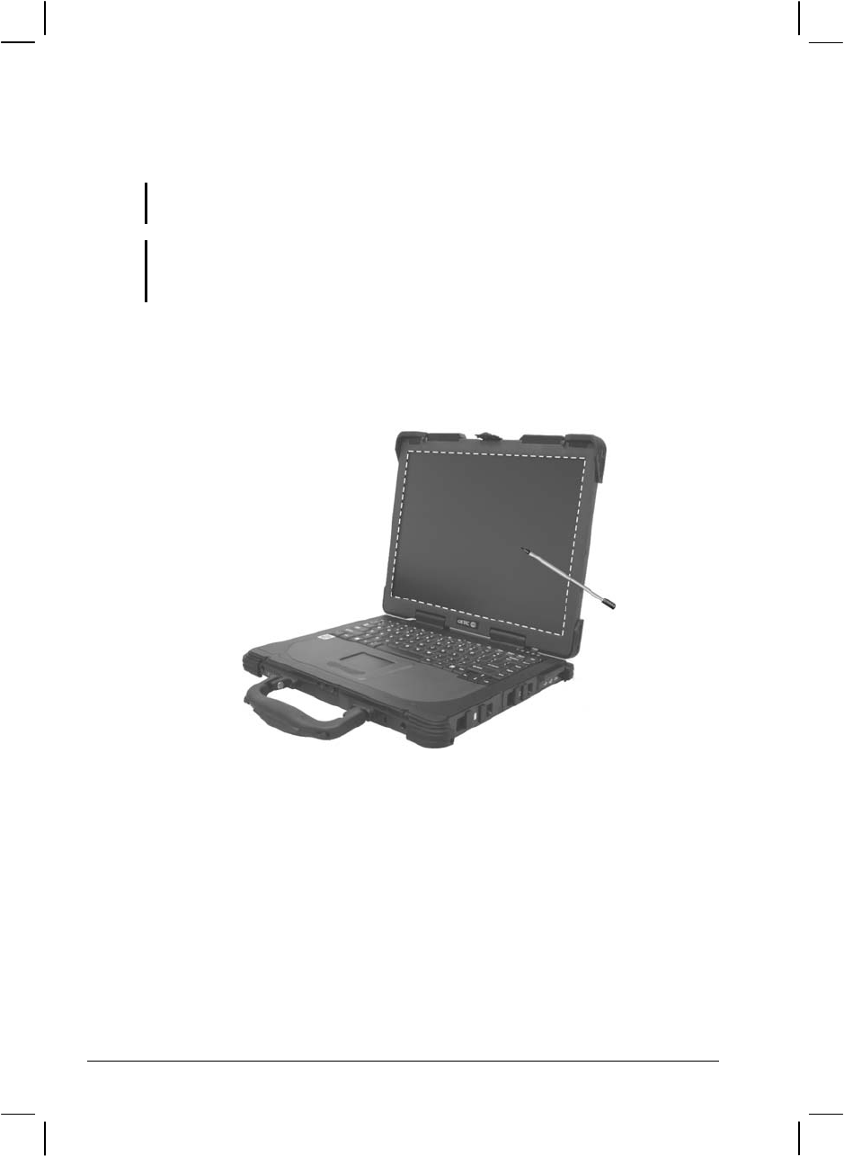
Using the Touchscreen (Optional)
NOTE: Make sure the “Serial Port COM3 (Touchscreen)” item is set properly in the
SCU program. (See “Advanced Menu” in chapter 5 for information.)
CAUTION: Do not use a sharp object such as a ballpoint pen or pencil on the
touchscreen. Doing so may damage the touchscreen surface. Use the included
touchscreen pen (option) located on the handle.
The touchscreen is a touch-sensitive device that allows you to
communicate with the computer by controlling the location of the pointer
on the screen and making selection with the buttons.
The touchscreen needs a special device driver support that allows you to
easily use the computer without a mouse or touchpad. (For information
on installing the driver, see Chapter 6.)
2-12 Operating Your Computer

Here are some common terms that you should know when using the
touchscreen:
Term Action
Click/Point Tap gently on the touchscreen.
Double-click Tap twice on the touchscreen rapidly.
Drag and
drop Press lightly on the touchscreen and move your finger
until you reach your destination (drag). Finally, release
your finger (drop) when you finish dragging your selection
to the destination. The object will drop into the new
location.
Scroll To scroll is to move up and down or left and right in the
working area on the screen.
To move vertically, place your finger on the right edge of
the touchscreen and slide your finger up and down along
the edge. To move horizontally, place your finger on the
bottom edge of the touchscreen and slide your finger left
and right.
This function works only after you install the touchscreen
driver supplied with the computer and it may not work for
all applications.
Operating Your Computer 2-13

Using the Hard Disk Drive
Your computer comes with a removable hard disk drive as drive C. A
hard disk drive is a storage device with non-removable, rotating,
magnetic storage platters inside it. It is where your operating system and
application software programs are stored.
Your hard disk drive is a 2.5-inch IDE (Integrated Drive Electronics) hard
disk drive. This type of drive embodies the latest in fast, reliable mass
storage by integrating all the control circuitry necessary for operation
directly onto the drive itself. This allows the drive manufacturer to
carefully optimize drive performance.
The system comes with a built-in heater that automatically turns on for
low temperature operation. The HDD indicator ( ) blinks red when
heater is on.
NOTE:
To use the HDD heater feature, the MTCCTRL driver supplied with your computer
must be installed (see chapter 6 for details).
Make sure the “HDD Heater” item is set properly in the SCU program. (See
“Advanced Menu” in chapter 5 for information.)
CAUTION:
Make regular backups of your data files from your hard disk drive to USB disks or
other storage media.
Never try to remove or install the hard disk drive while the computer is powered on.
Doing so can result in loss of data, and can damage the computer and the hard disk
drive’s sensitive circuitry.
Never turn off or reset the computer while the hard disk drive in-use indicator is on.
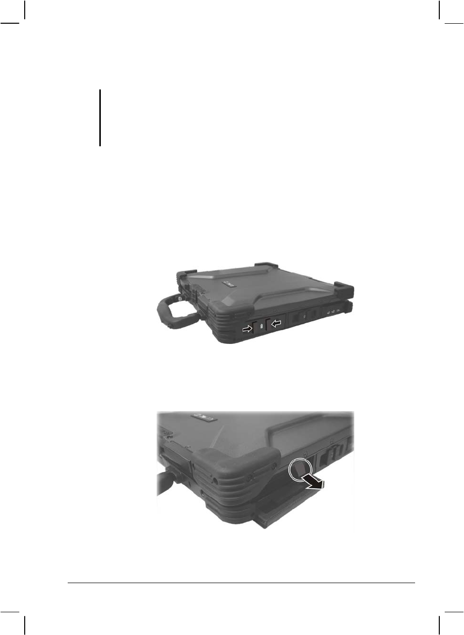
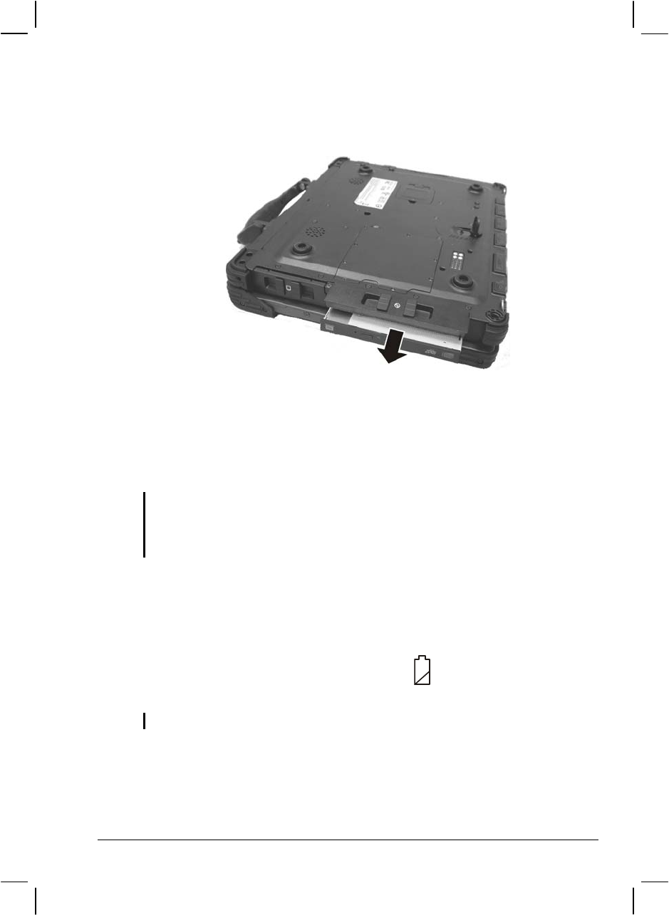
Replacing the Hard Disk Drive
To replace the hard disk drive:
4. Make sure that system power is off.
5. Remove the battery pack (see chapter 3 for details).
6. Locate the hard disk drive slot on the left side of the system.
2-14 Operating Your Computer
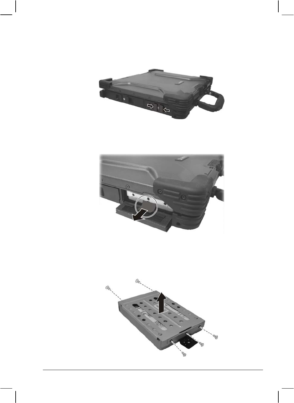
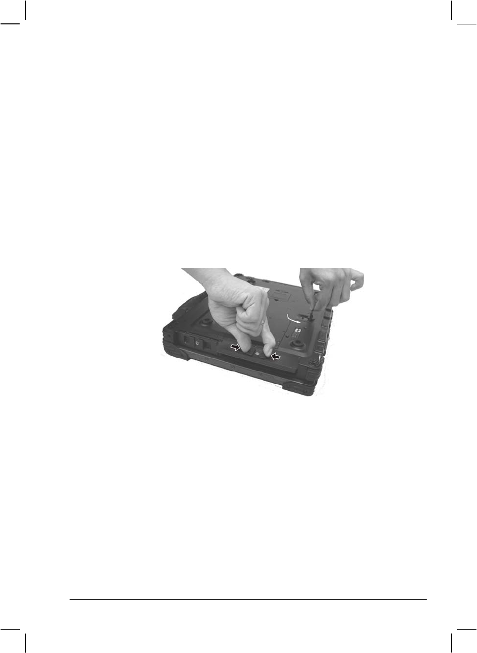
7. Open the hard disk drive slot cover by pressing on both sides of the
release latch using your thumb and index fingers.
8. Pull on the ribbon film to remove the hard disk drive compartment.
9. Remove the three front and two rear screws securing the hard disk
drive to the compartment and remove the compartment cover.
Operating Your Computer 2-15

10. Place the new hard disk drive into the compartment and tighten the
three front and two rear screws.
11. Slide the HDD compartment into the slot until it reaches the end.
12. Close the hard disk drive slot cover to secure the HDD compartment.
2-16 Operating Your Computer

Using the Optical Drive
Depending on the model, your computer comes with a CD, Combo drive,
or DVD dual recorder located on the left side of the computer. This drive
is usually configured as drive D.
The drive uses removable 5.25-inch silver discs, which look like standard
music discs. It is an ideal medium to use for distributing multimedia
because of the huge amount of data that a disc can store.
Depending on the model, your drive is one of the following:
CD drive can read CDs, audio CDs, CD-R, and CD-RW discs.
Combo drive can work both as a CD drive (reading DVD discs in
addition to CDs, audio CDs and CD-R/-RW discs), and also as a CD
recorder (writing to CD-R/-RW discs).
DVD Dual drive besides the Combo drive function, can write to
DVD+R/+RW/-R/-RW discs.
NOTE: If the CD/Combo/DVD Dual drive would be operating for more than half an hour
(such as showing a DVD title), use the AC power source instead of the battery. If not,
the battery may run out of power before the operation is complete.
CAUTION:
When inserting a disc, do not use force.
Make sure the disc is correctly inserted into the tray, and then close the tray.
Do not leave the CD tray open. Also, avoid touching the lens in the tray with your
hand. If the lens becomes dirty, the disc may malfunction.
Do not wipe the lens using materials with rough surface (such as paper towel).
Instead, use a cotton swab to gently wipe the lens.
FDA regulations require the following statement for all laser-based devices:
“Caution, Use of controls or adjustments or performance of procedures other than
those specified herein may result in hazardous radiation exposure.”
NOTE: The CD/Combo/DVD Dual drive is classified as a Class 1 laser product. This
label is located on the drive.
Operating Your Computer 2-17
NOTE: For Combo/DVD Dual drive only.
This product incorporates copyright protection technology that is protected by method
claims of certain U.S. patents and other intellectual property rights owned by
Macrovision Corporation and other rights owners. Use of this copyright protection
technology must be authorized by Macrovision Corporation, and is intended for home
and other limited viewing uses only unless otherwise authorized by Macrovision
Corporation. Reverse engineering or disassembly is prohibited.
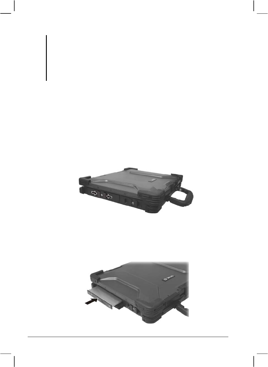
Installing the Optical Drive
To install the optical drive:
1. Make sure that the computer is off.
2. Locate the optical drive bay on the left side of the computer.
3. Open the optical drive bay cover by pressing on both sides of the
release latch using your thumb and index fingers.
If no module is inside the drive bay
4. Insert the optical drive into the drive bay.
2-18 Operating Your Computer
5. Close the optical drive bay cover to secure the drive in place.
If another module is inside the drive bay
4. Check to see if any other module is installed in the optical drive bay.
If no other module is inside, proceed directly to step 10.
5. Close the optical drive bay cover.
6. Gently place the computer upside down.
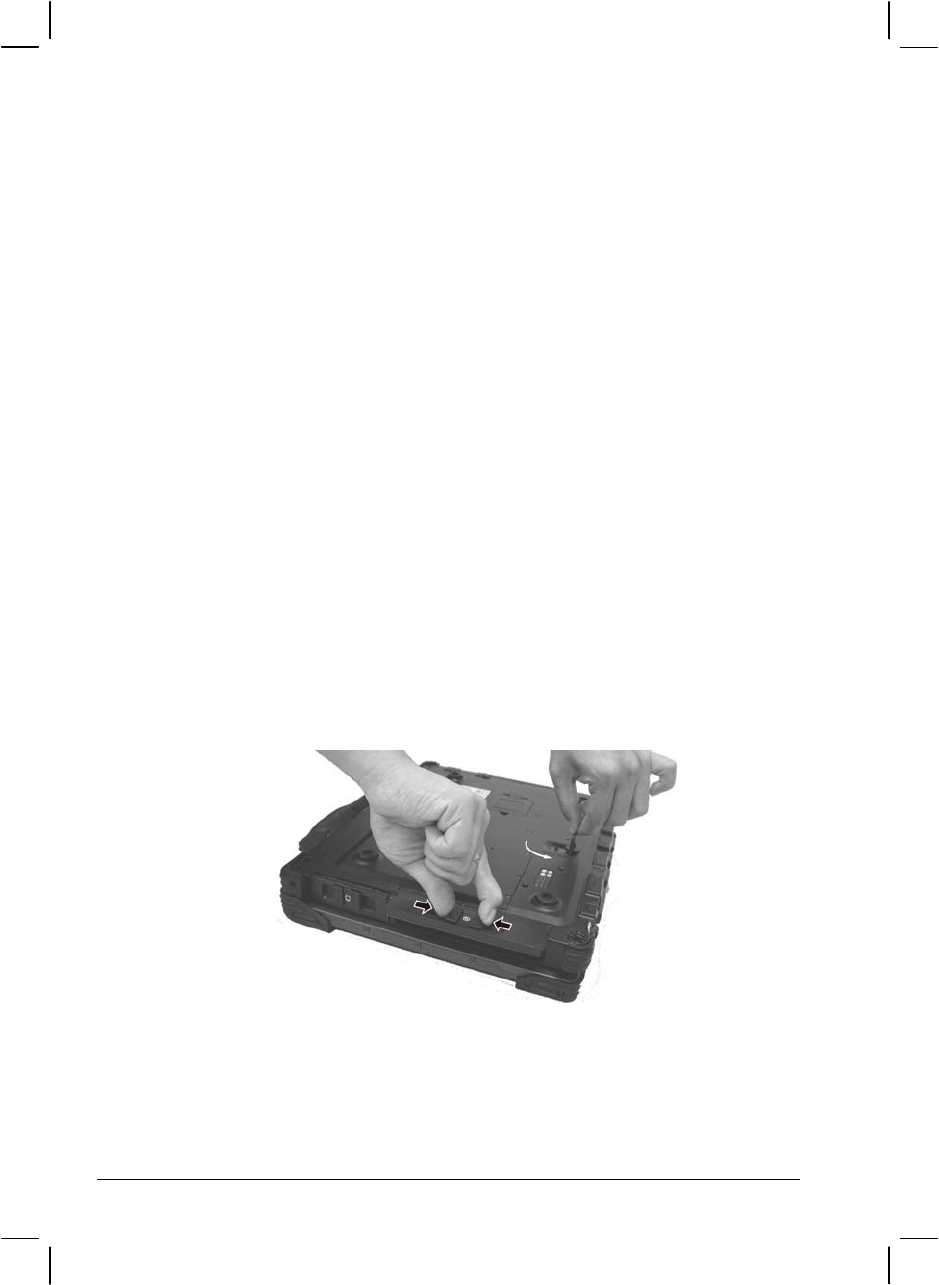
7. Open the optical drive bay cover again by pressing on both sides of
the release latch using your thumb and index fingers.
8. Lift up the handle of the optical drive release knob and turn it
counter-clockwise.
9. Pull out the existing module.
Operating Your Computer 2-19
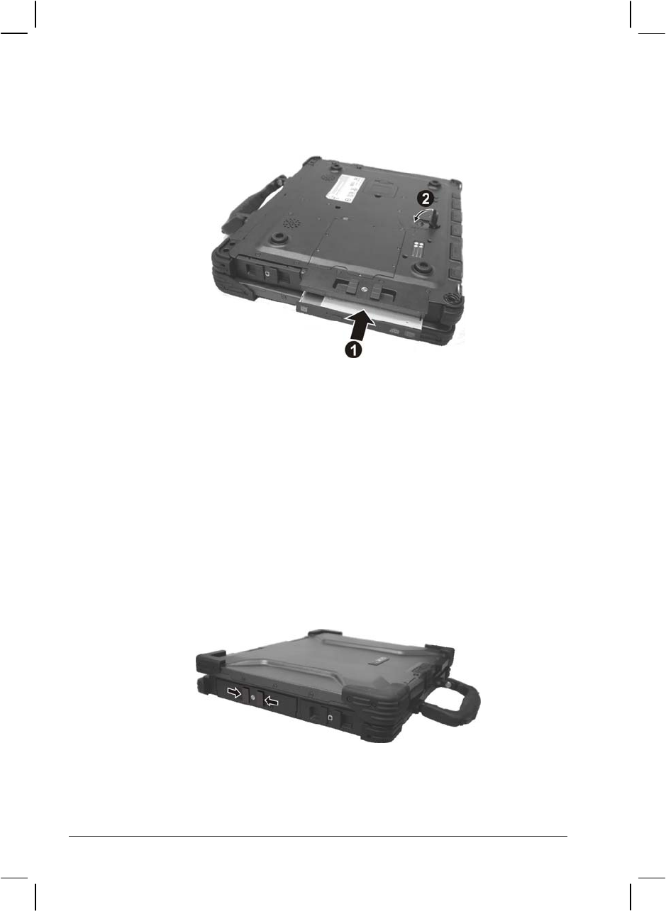
10. Insert the optical drive into the drive bay () and return the release
knob ().
11. Close the optical drive bay cover to secure the drive in place.
Inserting and Removing a Disc
Follow this procedure to insert or remove a disc.
1. Turn on the computer.
2. Locate the optical drive bay on the left side of the computer.
3. Open the optical drive bay cover by pressing on both sides of the
release latch using your thumb and index fingers.
4. Press the eject button and the drive tray will slide out partially. Gently
pull on it until it is fully extended.
2-20 Operating Your Computer
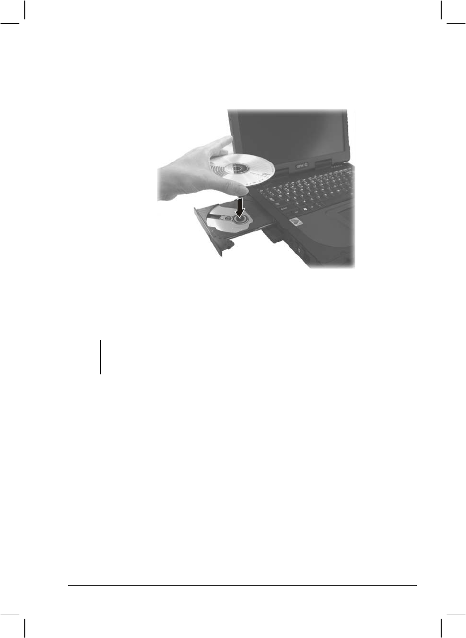
5. To insert a disc, place down the disc in the tray with its label facing
up. Slightly press the center of the disc until it clicks into place.
To remove a disc, hold the disc by its outer edge and lift it up from the
tray.
6. Gently push the tray back into the drive.
NOTE: In the unlikely event that you are unable to release the drive tray by pressing the
eject button, you can manually release the disc. (See “Optical Drive Problems” in
Chapter 8.)
Operating Your Computer 2-21

Using the Video Features
The video subsystem of your computer features:
14.1-inch TFT (Thin-Film Transistor) color LCD display with
1024×768 XGA (Extended Video Graphics Array) resolution, or
15-inch TFT color LCD display with 1400×1050 SXGA+ (Super
Extended Video Graphics Array) resolution.
64 MB shared with system memory.
LCD backlight to help you see the display during poor lighting
conditions. Press Fn+F7 to turn it on/off (see Hot Keys in this
chapter).
Simultaneous display on LCD and external monitor, which is useful
when you have a presentation as you can control the screen from your
computer and face the audience at the same time.
Dual view capability, which allows you to expand your desktop on
the screen to another display device so that you have more desktop
space to work on.
Power Management.
Touchscreen function (option).
High contrast LCD display (option for 14.1-inch panel).
NOTE:
To take advantage of the enhanced video capabilities and before using the dual
view capability, the device driver supplied with your computer must be installed
(see chapter 6 for details).
The computer enters Standby or Hibernation mode when the LCD is closed. If you
want to use the computer with the LCD closed, set None to the “When I close the lid
of my portable computer” option in the Power Management Properties. Thus the
computer does not enter Standby or Hibernation mode when the LCD is closed.
Configuring the Display Modes
NOTE: When using CRT only, the resolution would depend on the supported resolution
by the CRT.
2-22 Operating Your Computer

Your computer has been set to a default resolution and number of colors
before shipment. You can view and change display settings through your
operating system. See your operating system documentation or online
help for specific information.
For displaying in higher resolutions, you can connect an external CRT
monitor that supports higher resolutions. (See “Connecting an External
Monitor” in Chapter 4 for more information.)
The following table lists the display modes supported by your computer.
Display Mode LCD Only CRT Only Simultaneous Display
Resolution Colors
16-bit √ √ √
1024×768
32-bit √ √ √
16-bit √ √ √
1400×1050
32-bit √ √ √
16-bit √ √ √
1600×1200
32-bit √ √ √
TABLE NOTE:
16-bit = High Color or 65,536 (64 K) colors; 32-bit = True Color 16,770,000 (16 M)
colors.
When using CRT only, the resolution would depend on the supported resolution by
the CRT.
Operating Your Computer 2-23
Using the Audio Features
NOTE:
To take advantage of the enhanced audio capabilities, the device driver supplied
with your computer must be installed (see chapter 6 for details).
If you experience interference while recording, try lowering the microphone
recording volume.
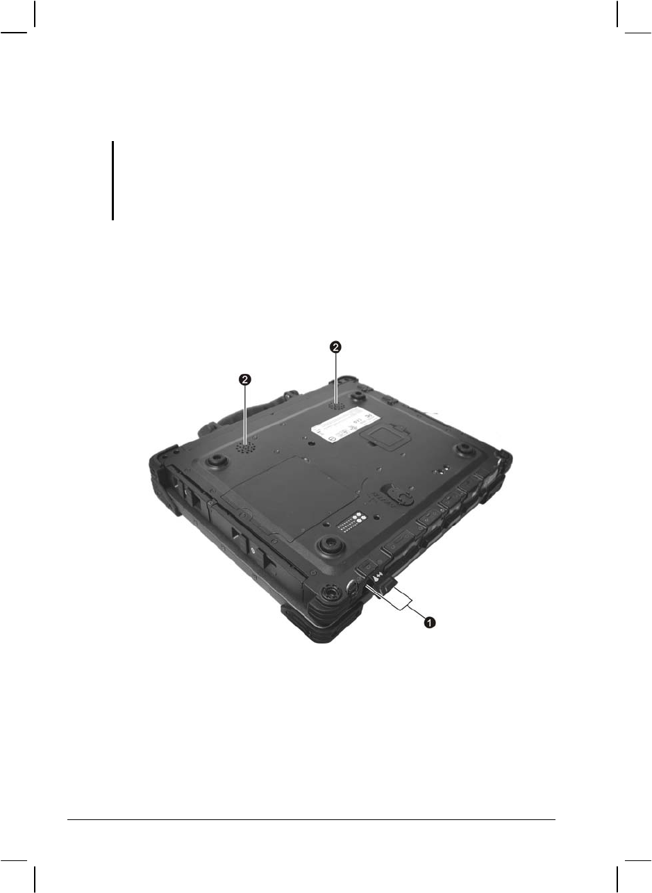
The audio subsystem of your computer features:
External audio connectors () on the rear, and
A set of speakers () on the bottom side
Ways of playing and recording sound vary with the operating system
used. See your operating system documentation or online help for
specific information.
2-24 Operating Your Computer
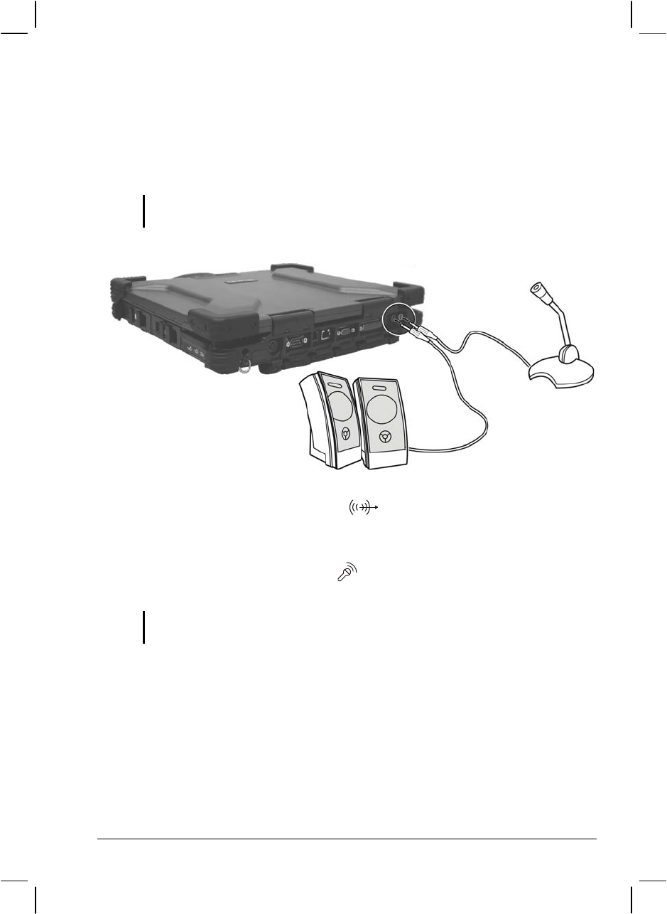
Connecting Audio Devices
For higher audio quality, you can send or receive sound through external
audio devices.
NOTE: After connecting an external audio device, make sure that you specify the use
of the correct audio device in Windows.
Audio Output Connector ( ) can be connected to the line-in
connector of powered speakers with built-in amplifiers, headphones,
or earphone set.
Microphone Connector ( ) can be connected to an external
microphone for recording voice or sound.
NOTE: When using external speakers/headphones or microphone, you cannot use the
internal one.
Operating Your Computer 2-25
Using the Communication Features
Using the LAN
NOTE: To take advantage of the LAN (Local Area Network) feature, the device driver
supplied with your computer must be installed (see chapter 6 for details).
The internal 10/100/1000Base-T Ethernet module allows you to connect
your computer to a network. It supports data transfer rate up to 1000
Mbps.
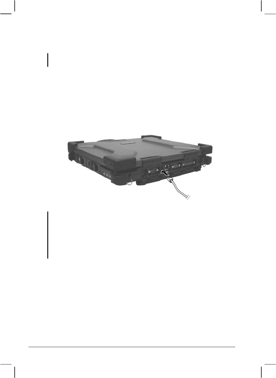
To connect the network cable to the LAN module, connect one end of the
LAN cable to the RJ-45 connector on the computer and the other end to
the network hub. The LAN indicator ( ) glows to indicate that the
computer is ready for LAN connection.
2-26 Operating Your Computer

Using the Wireless LAN (WLAN)
An internal Mini PCI wireless LAN module have been pre-installed by
your computer manufacturer at the factory. This allows you to access
corporate networks or the Internet in a wireless environment.
The WLAN features include:
Peer-to-Peer (Ad-Hoc) and Access Point (Infrastructure) modes
support
WEP (Wired Equivalent Privacy) 64/128-bit data encryption
IEEE 802.11a/b/g standard compliance
Technology 802.11a 802.11b 802.11g
Stated Maximum
Throughput (Mbps) 54 11 54
Data Rates (Mbps) 54, 48, 36, 24, 18,
12, 9, 6 11, 5.5, 2, 1 54, 36, 18, 9
Band (GHz) 5.15 ~ 5.35 2.412 ~ 2.462 2.4
Modulation
Technology OFDM (Orthogonal
Frequency Division
Multiplexing)
DSSS (Direct
Sequence Spread
Spectrum)
OFDM (Orthogonal
Frequency Division
Multiplexing)
NOTE: 802.11g mode is backward compatible with 802.11b mode.
To take advantage of the WLAN feature, make sure that the PROSet
driver is installed correctly (see Chapter 6 for details). If your WLAN
module was provided by your dealer instead of the computer
manufacturer, contact your dealer for the correct driver to use.
Configuring the WLAN
After driver installation, you can use the WLAN utility to configure and
monitor your WLAN connection. If you are using Windows XP, you can
also use its built-in WLAN utility. Follow this procedure to launch the
WLAN utility in Windows XP:
1. Select Control Panel from the Start menu.
2. Click Network and Internet Connections.
Operating Your Computer 2-27

3. Click Network Connections, then double-click the Wireless Network
Connection icon .
4. Click Properties in the Wireless Network Connection Status dialog
box.
5. You can configure your WLAN settings in the Wireless Network
Connection Properties dialog box.
Turning Off/On the WLAN Radio
NOTE: The FAA (Federal Aviation Agency) has deemed it unsafe to operate wireless
devices in aircraft as this may interfere with flight safety. Remember to turn off wireless
LAN when using your computer in the airplane.
Your computer has a built-in Fn+F11 WLAN hot key to switch the WLAN
on/off (see “Hot Keys” in Chapter 2). The WLAN indicator ( ) glows
to indicate that the computer is ready for WLAN connection.
If you need to temporarily turn off the radio, press Fn+F11. To resume
network connection, press Fn+F11 again.
It takes approximately 30 seconds for your computer to make a successful
WLAN connection and approximately 10 seconds to disconnect.
Connecting to a Wireless Network
To connect to a wireless network:
1. Make sure that the WLAN radio is on.
2. Click Start and then All Programs.
3. Click Intel PROSet Wireless and then Intel PROSet Wireless.
2-28 Operating Your Computer
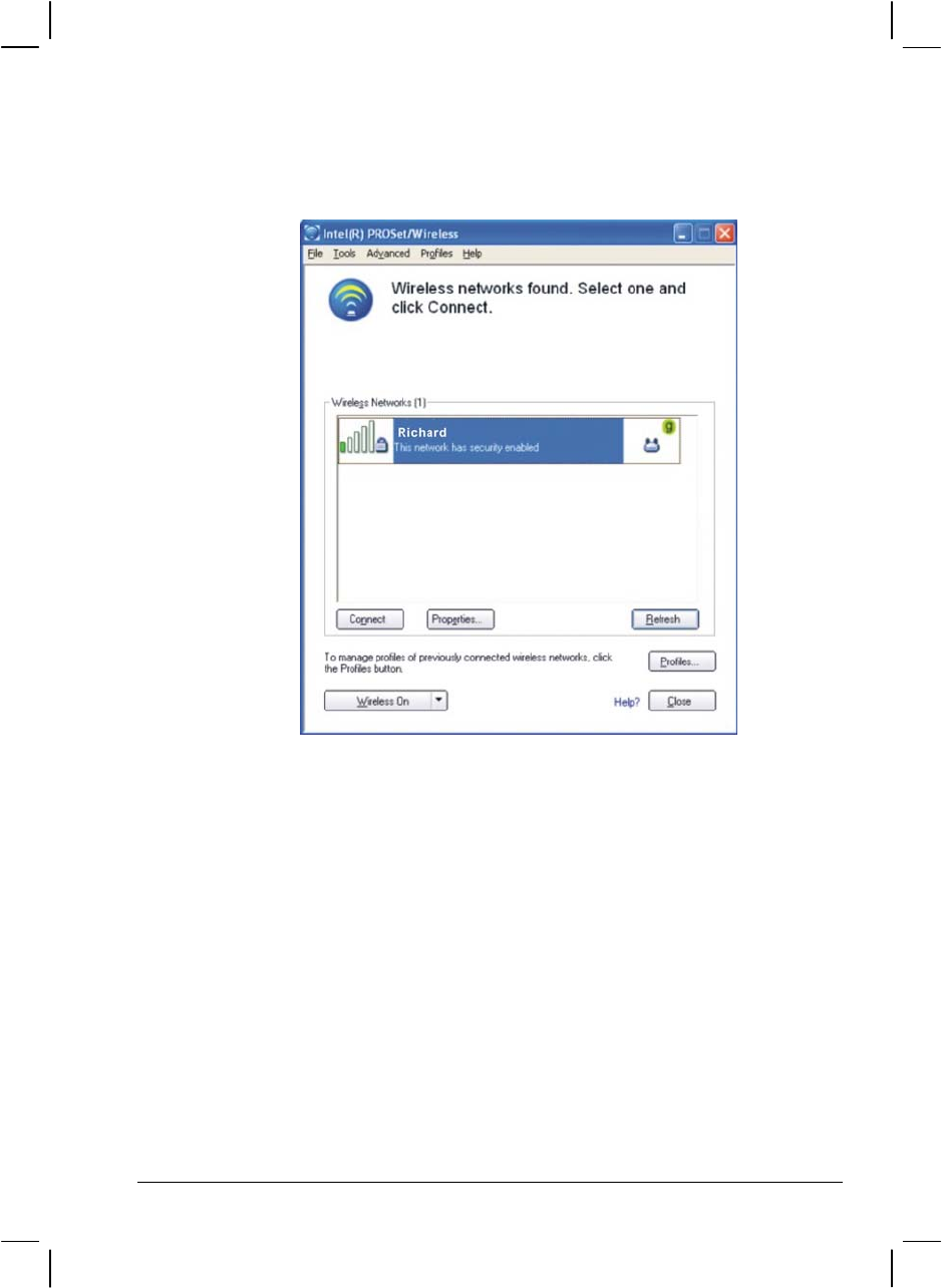
4. If any wireless network is detected, the following window appears on
screen.
5. Click to select a wireless network to connect to, and then click
Connect.
6. Depending on the settings, you may be asked to enter a wireless
security password (encryption key).
For more information on the Intel PROSet Wireless utility, click Help? in
the Intel(R) PROSet/Wireless window.
Operating Your Computer 2-29
Using the Modem
NOTE: To take advantage of the modem feature, the device driver supplied with your
computer must be installed (see chapter 6 for details).
The internal 56 K fax/data modem allows you to use the telephone line to
communicate with others by fax, email, or connect to an online service or
bulletin board.
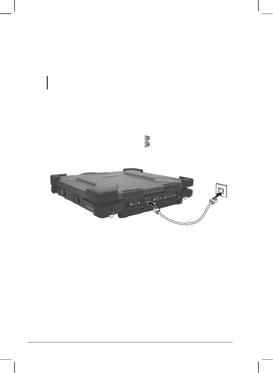
To connect the telephone line to the modem, connect one end of the
modem cable to the RJ-11 connector on the computer and the other end to
the phone line.
NOTE:
When using communication software, you may have to disable power
management.
Set the COM port of the modem to COM3.
Set parameters such as modem speed (baud rate) and line type (pulse dialing or
tone dialing).
Do not enter Standby mode when using communication software.
2-30 Operating Your Computer

Connecting Using GPRS
Your computer can receive General Packet Radio Services (GPRS), a
high-speed data-only service that transmits data over a mobile telephone
network. In addition, GPRS provides permanent on-line connection.
To use GPRS, you must have a subscription to the function with a service
provider that supports GPRS.
To connect to a GPRS network, you must configure a connection for that
service on your computer.
Using the GPS (Optional)
NOTE: To take advantage of the GPS feature, the USB-to-COM driver supplied with
your computer must be installed (see chapter 6 for details).
Navigation and positioning are crucial to so many activities. To try to
figure out where you are and where you are going, you need GPS
technology. The Global Positioning System (GPS) is a worldwide
radio-navigation system.
Turning On/Off the GPS
Your computer has a built-in Fn+F12 GPS hot key to switch the GPS
on/off (see “Hot Keys” in this chapter).
Using Bluetooth (Optional)
NOTE: To take advantage of the Bluetooth feature, the Bluetooth driver supplied with
your computer must be installed (see chapter 6 for details).
Depending on your model, your computer may incorporate the Bluetooth
capability for short-range (about 10 meters) wireless communications
between devices without requiring a cable connection.
With Bluetooth, data can be transmitted through walls, pockets and
briefcases as long as two devices are within range. By default, your
computer’s Bluetooth feature is active (always ON) upon booting your
computer and is in the general discoverable and pairable mode.
2-32 Operating Your Computer
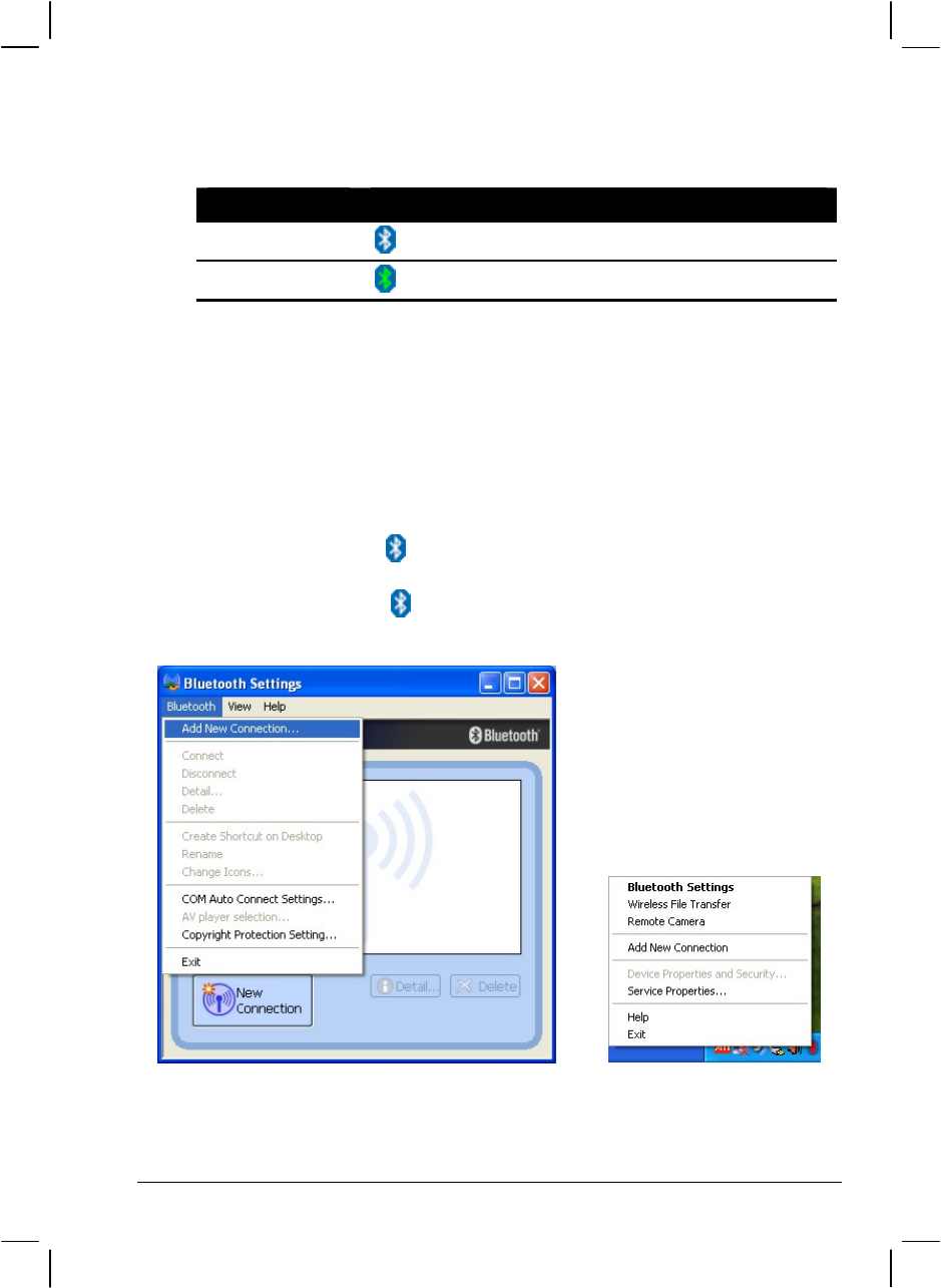
The status of the Bluetooth connection is indicated by the Bluetooth icon
located in the system tray in the lower-right part of the screen.
Status Icon
On (blue with white logo)
Connected (blue with green logo)
You can use the Bluetooth Utility to configure Bluetooth connection
settings and transfer files.
Connecting to Another Bluetooth Device
1. Make sure that the target Bluetooth device is turned on, discoverable
and within close range. (See the documentation that came with the
Bluetooth device.)
2. Double-click the icon, then click on New Connection or click on
Bluetooth, then Add New Connection . . .
Or right-click the icon, and then click on Add New Connection.
or
Operating Your Computer 2-33
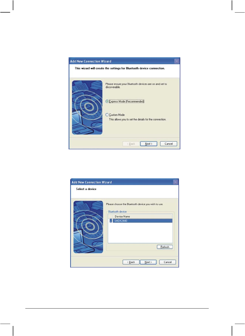
3. The Add New Connection Wizard window appears. Select Express
Mode (Recommended), then click on Next.
4. Select the device to connect to and click on Next.
5. Depending on the type of Bluetooth device that you want to connect
to, you will need to enter the pertinent information.
2-34 Operating Your Computer
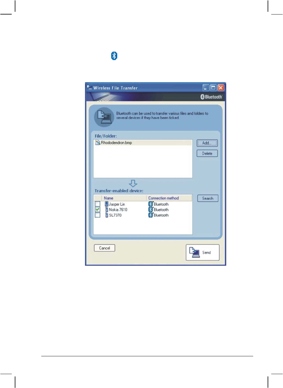
Sending a File
1. Right-click the icon, and then click Wireless File Transfer. The
following screen appears.
2. In the Wireless File Transfer window, click Add to browse for the file
to send. The file(s) will show on the File/Folder window.
3. Click the target device from the Transfer-enabled device window, and
then click Send to start the transfer procedure.
Operating Your Computer 2-35
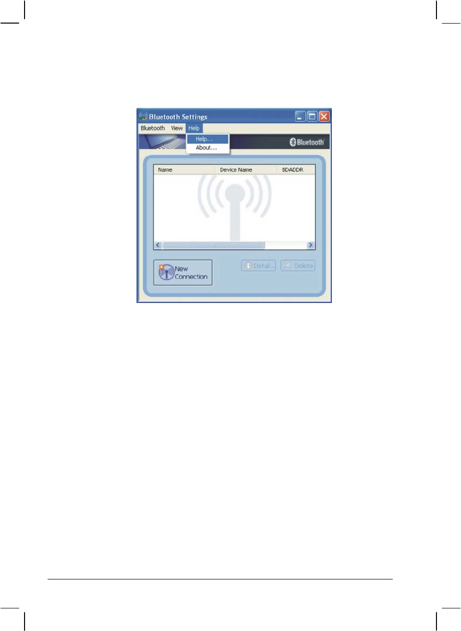
For detailed information on using the Bluetooth Utility, see the Bluetooth
Utility Help on your computer by clicking on Help, then Help . . .
2-36 Operating Your Computer
Operating Your Computer 2-37
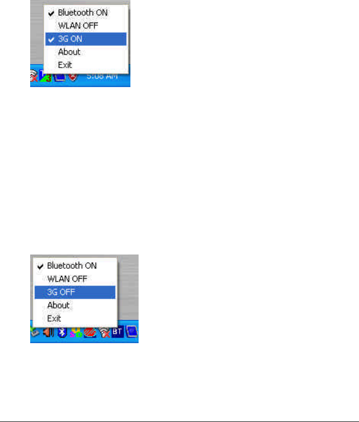
HELP FOR ModuleSW PROGRAM
Version: ModuleSW 1.0.1.9
The ModuleSW program can to set BlueTooth/WirelessLan/3G modules
power ON or OFF and keep the state to system startup.
There are 5 subitem can be selection. The menu and subitem as follow:
The user can select and click BlueTooth or WirelessLan(WLAN) or 3G
subitem to switch module power state.
For example:
If user select and click "3G ON" subitem . ModuleSW will switch 3G module
power ON state to OFF and When system startup(or restart), ModuleSW
will keep 3G module to power OFF state.
2-38 Operating Your Computer
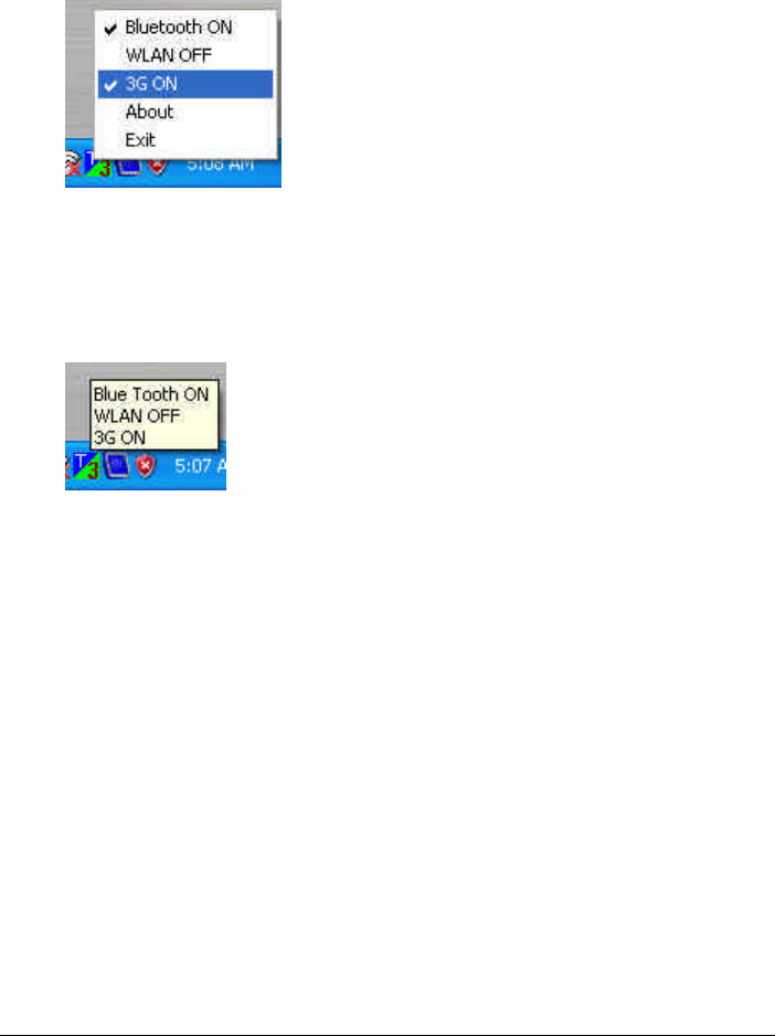
If user select and click "3G OFF" subitem . ModuleSW will switch 3G
module power OFF state to ON and When system startup(or
restart) ,ModuleSW will keep 3G module to power ON state.
If user move cursor to ModuleSW tray-icon than show
BuleTooth/WirelessLan/3G module power state.

CHAPTER 3
Managing Power
Your computer operates either on external AC power or internal battery
power.
This chapter tells you how you can effectively manage power. To
maintain optimal battery performance, it is important that you use the
battery in the proper way.
The topics in this chapter include:
What is an AC adapter
How to charge the battery pack
When and how to initialize the battery pack
How to check the battery level
How to replace the battery pack
What happens when the battery is low and what actions to take
What is Power Management
How to save power

AC Adapter
CAUTION:
The AC adapter is designed for use with your computer only. Connecting the AC
adapter to another device can damage the adapter.
The AC power cord supplied with your computer is for use in the country where you
purchased your computer. If you plan to go overseas with the computer, consult
your dealer for the appropriate power cord.
When you disconnect the AC adapter, disconnect from the electrical outlet first and
then from the computer. A reverse procedure may damage the AC adapter or
computer.
When unplugging the connector, always hold the plug head. Never pull on the cord.
The AC adapter serves as a converter from AC (Alternating Current) to
DC (Direct Current) power because your computer runs on DC power,
but an electrical outlet usually provides AC power. It also charges the
battery pack when connected to AC power.
The AC adapter operates on any voltage in the range of 100 ~ 240 V AC.
3-2 Managing Power

Battery Pack
The battery pack is the internal power source for the computer. It is
rechargeable using the AC adapter.
The operating time of a fully charged battery pack depends on how you
are using the computer. When your applications often access peripherals,
you will experience a shorter operating time.
NOTE: Care and maintenance information for the battery is provided in the “Battery
Pack Guidelines” section in Chapter 7.
Charging the Battery Pack
NOTE:
Charging will not start if the battery pack’s temperature is or above 60 °C (140 °F).
The charging process will stop and the Battery Charge Indicator flashes amber and
green alternatively when the battery’s temperature gets above 60 °C (140 °F). If
this happens, the battery pack may be damaged. Please contact your dealer.
During charging, do not disconnect the AC adapter before the battery has been fully
charged; otherwise you will get a prematurely charged battery.
To charge the battery pack, connect the AC adapter to the computer and
an electrical outlet. The Battery Charge Indicator ( ) on the computer
glows amber to indicate that charging is in progress. You are advised to
keep the computer power off while the battery is being charged. When the
battery is fully charged, the Battery Charge Indicator glows green.
The charging times are as follows:
Charging Time
Battery Type Computer is Off
Computer is On and in Idle
State as well as when
Computer is Off and
battery pack’s temperature
gets above 45 °C (113 °F)
7200 mAh /
11.1 V 2.5 hours
(150 minutes) 5.8 hours
(350 minutes)
CAUTION: After the computer has been fully recharged, do not immediately disconnect
and reconnect the AC adapter to charge it again. Doing so may damage the battery.
Managing Power 3-3

NOTE: The battery level may automatically lessen due to the self-discharge process
(0.21 % per day), even when the battery pack is fully charged (100 %). This happens no
matter if the battery pack is installed in the computer.
Initializing the Battery Pack
You need to initialize a new battery pack before using it for the first time
or when the actual operating time of a battery pack is much less than
expected.
Initializing is the process of fully charging, discharging, and then
charging. It can take several hours.
1. Make sure the computer power is turned off. Connect the AC adapter
to fully charge the battery pack.
2. After the battery pack is fully charged, turn on the computer.
3. Disconnect the AC adapter and leave the computer on until the
battery is fully discharged. The computer will shut down
automatically, depending on your settings in Windows.
4. Connect the AC adapter to fully charge the battery pack.
Checking the Battery Level
When two batteries exist on the system, the battery’s discharge sequence
is from the optional secondary battery (located on the optical drive bay) to
the primary battery (located on the right side). When the battery charge
on the optional secondary battery falls below 9.1 V, then power usage
will switch to the primary battery. When the battery charge on the
primary battery falls below 9.1 V, then system will shutdown.
NOTE: Any battery level indication is an estimated result. The actual operating time can
be different from the estimated time, depending on how you are using the computer.
You can check the approximate battery level using the battery meter
function of the operating system. To read the battery level in Windows,
click the icon on the taskbar. (Click the icon if the computer is
using AC power.)
3-4 Managing Power
Replacing the Primary Battery Pack
CAUTION:
There is danger of explosion if the battery is incorrectly replaced. Replace the
battery only with the computer manufacturer’s optional battery packs. Discard used
batteries according to the dealer’s instructions.
Do not attempt to disassemble the battery pack.
To replace the primary battery pack, follow these steps:
1. Make sure the computer is not turned on or connected to AC power.
2. Locate the battery slot on the right side of the system.
3. Open the slot cover by pressing on both sides of the release latch
using your thumb and index fingers.
4. Pull on the ribbon strip to remove the battery pack and replace it with
a new one.
Managing Power 3-5
5. Slide the new battery pack all the way into the slot. Make sure to
observe the correct orientation (the ribbon strip must face outward for
future battery back removal).
6. Close the slot cover to secure the battery pack.
Installing the Secondary Battery Pack
If you often rely on battery power for a long period of time while
traveling, you may consider the purchase of an additional battery pack
from your dealer and keep it with you in a fully charged state as a backup.
To install the secondary battery pack, follow these steps:
1. Make sure the computer is not turned on or connected to AC power.
2. Locate the optical drive slot on the left side of the system.
3. Gently place the computer upside down.
4. Open the slot cover by pressing on both sides of the release latch
using your thumb and index fingers.
5. Lift up the handle of the optical drive release knob and turn it
counter-clockwise.
3-6 Managing Power
6. The optical drive will slide out partially. Gently pull on it to remove
it.
7. Slide the secondary battery pack all the way into the slot. Make sure
to observe the correct orientation (the ribbon strip must face outward
for future battery pack removal).
8. Close the slot cover to secure the secondary battery
NOTE: The system supports the secondary battery hot-swap function, providing you
the ability to replace the battery even during system on. Hot swap means that you can
remove the secondary battery pack and replace it with another one without significant
interruption to the system (without turning off the system).
Battery Low Signals and Actions
Battery Low occurs when the battery has approximately 10 % (Windows
default setting) of its charge remaining. The computer gives warning
messages and the Battery Power Indicator ( ) blinks amber (orange) to
alert you to take actions.
NOTE: You can set up your threshold and signals of Battery Low under Windows.
Immediately save your data upon Battery Low. The remaining operating
time depends on how you are using the computer. If you are using the
audio subsystem, hard or optical drives, PC card, the battery might run
out of charge very quickly.
Managing Power 3-7

Always respond to Battery Low by placing your computer on Standby or
Hibernation mode, turning off the computer, or connecting the AC
adapter.
If you do not take any action, the computer will automatically hibernate
and turn off.
CAUTION:
If you are using a flash PC card, do not access the card during battery low periods.
This is because the access may take longer than the time it takes the battery to run
out of charge, thus making your access to the card unsuccessful.
If you fail to save your data when the battery completely runs out of charge, then
you lose your data.
3-8 Managing Power

Power Management
Your computer supports ACPI (Advanced Configuration and Power
Interface) for power management. The power management feature allows
you to reduce the power consumption for energy saving.
With an ACPI-compliant operating system such as Windows 2000 and
Windows XP, power supply to different computer components is
controlled on an as-needed basis. This allows maximum power
conservation and performance at the same time.
In general, Windows’ power management works in this way:
What… When…
Power to the hard disk is turned off When the hard disk has been idle for a
set period.
Power to the display is turned off When the display has been idle for a set
period.
When the entire system has been idle
for a set period.
When you press Fn+F10. *
When you close the cover. *
The computer enters Standby mode.
The hard disk and display are turned
off and the entire system consumes
less power.
When you press the power button. *
When you press the power button. *
When you press Fn+F10. *
The computer enters Hibernation
mode. (See the next subsection for
more information.) When you close the cover. *
* depends on your settings in Windows.
For detailed information on power management, see Windows’ Help.
Managing Power 3-9

Hibernation
Hibernation is a very useful feature. People frequently open many
applications when they use computers. It takes some time to get all these
applications open and running, and normally they all have to be closed
before the system can be turned off.
When you use the hibernation feature, you do not have to close the
applications. The computer stores the state of your computer to a file on
the hard disk and then shut down. The next time you turn on your
computer, you return to exactly where you left off.
3-10 Managing Power

Power-Saving Tips
In addition to your computer’s automatic power management, you can do
your part to maximize the battery’s operating time by following these
suggestions.
Do not disable Power Management.
Decrease the LCD brightness to the lowest comfortable level.
Disable the parallel and serial ports if no devices are connected to
these ports. (See “Advanced Menu” in Chapter 5.)
If you work with an application that features wireless connectivity
(LAN/modem/GPS/Bluetooth), exit the application when you finish
using it.
If you have a PC card installed, remove it when not in use. Some PC
cards drain power even while they are inactive.
Turn off the computer when you are not using it.
Managing Power 3-11

3-12 Managing Power

CHAPTER 4
Expanding Your Computer
You can expand the capabilities of your computer by connecting other
peripheral devices. When using a device, be sure to read the instructions
accompanying the device together with the relevant section in this
chapter.
This chapter gives guidelines on installing and using these devices:
External monitor
USB device
Parallel device
Serial device
IR device
IEEE 1394B device
PC card
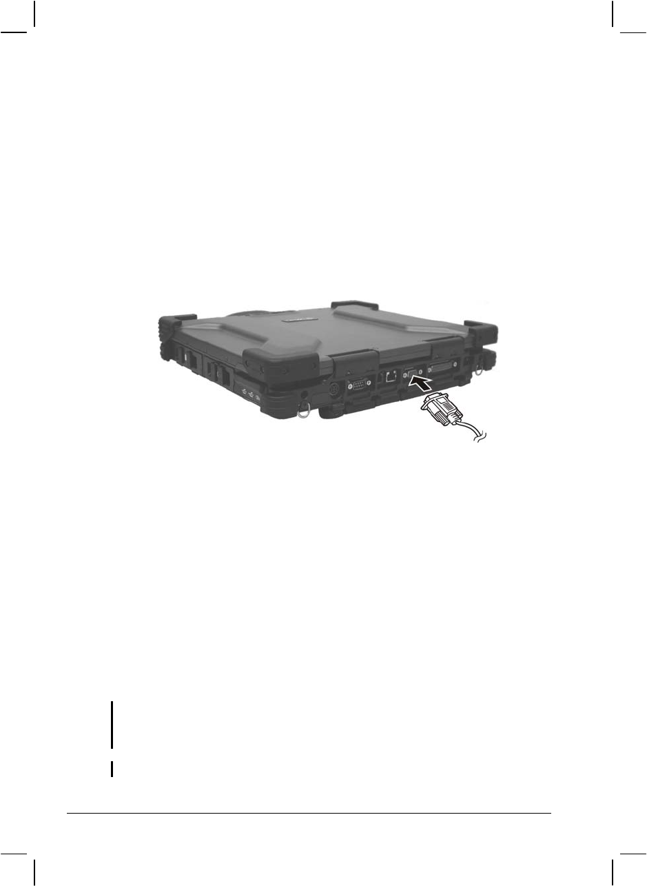
Connecting an External Monitor
If you want the benefits of a larger display screen with higher resolution,
you can connect an external CRT monitor to your computer.
Follow this procedure to connect an external monitor:
1. Make sure that the computer is not turned on.
2. Plug the monitor’s D-type signal connector to the computer’s VGA
port.
3. Plug one end of the monitor’s power cord into the power socket on
the monitor and the other end to an electrical outlet.
4. To use the monitor, turn on the monitor before turning on the
computer.
5. The monitor should respond by default. If not, you can switch the
display to the monitor or to both (simultaneous display) by pressing
Fn+F9. In Windows, you can also change the display through the
settings in Display Properties.
6. You can change display settings through your operating system. See
your operating system documentation or online help for specific
information.
CAUTION: Do not disconnect the external monitor while the computer is in Standby
mode or Hibernation mode. If no external monitor is connected when the computer
resumes, the LCD remains blank and the output is not displayed.
NOTE: Make sure that the device driver is installed correctly (see chapter 6 for details).
4-2 Expanding Your Computer
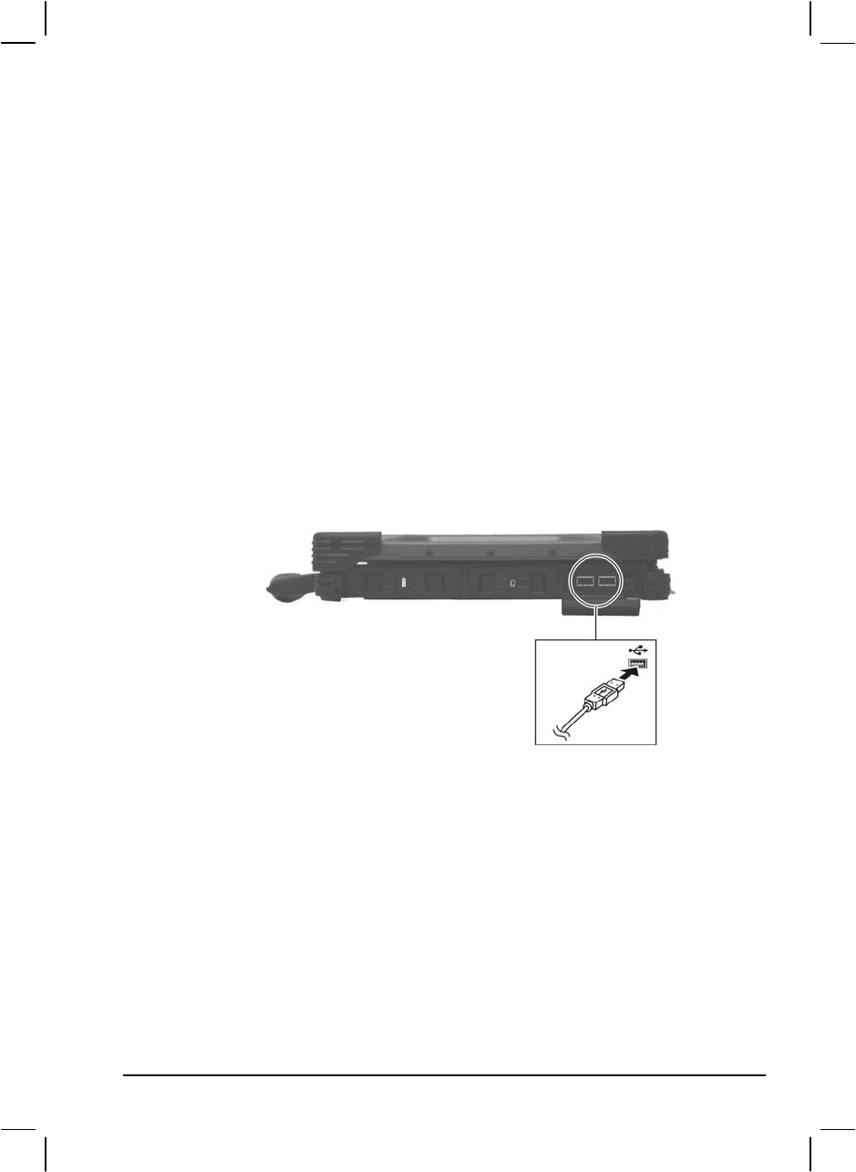
Connecting a USB Device
Your computer has two USB ports that supports transfer rates up to 12
MB/s for USB 1.1 devices and 480 MB/s for USB 2.0 devices, such as
digital camera, scanner, printer, modem, and mouse.
USB is specified to be an industry standard extension to the PC
architecture. It supports “Plug-and-Play” technology so you can install
and remove USB devices without turning off the computer. With its
multiple connection capability, up to 127 devices can be connected in a
daisy-chain configuration. In addition, you can use a USB hub that
converts a single USB connector into multiple ports where USB devices
can be connected.
To connect a USB device, simply plug the device cable to one of the USB
ports.
Expanding Your Computer 4-3
Connecting a Parallel Device
Your computer has a parallel port for connecting a parallel device such as
printer. The port supports ECP (Extended Capabilities Port) and EPP
(Enhanced Parallel Port) modes that turn the standard parallel port into a
high-speed bi-directional peripheral port.
Follow this procedure to connect a parallel device:
1. Make sure that the “Parallel Port” item is set properly in the BIOS
Setup program. (See “Advanced Menu” in Chapter 5 for
information.)
2. Make sure the computer is not turned on.
3. Plug the parallel device’s cable to the computer’s parallel port.
4. If the parallel device has independent power, plug its power cord into
an electrical outlet.
5. If the parallel device has its own power switch, turn on the device
before turning on the computer.
4-4 Expanding Your Computer
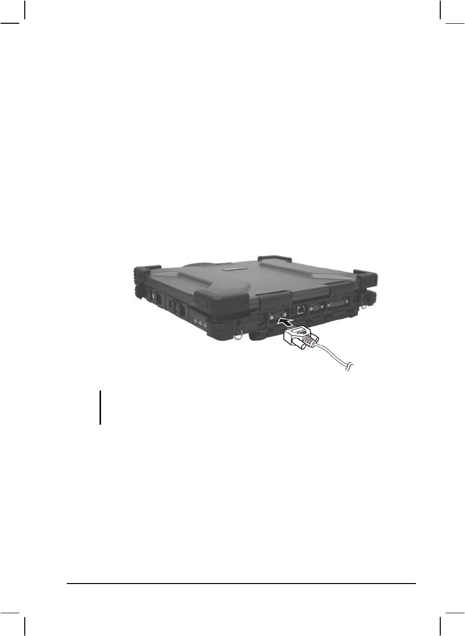
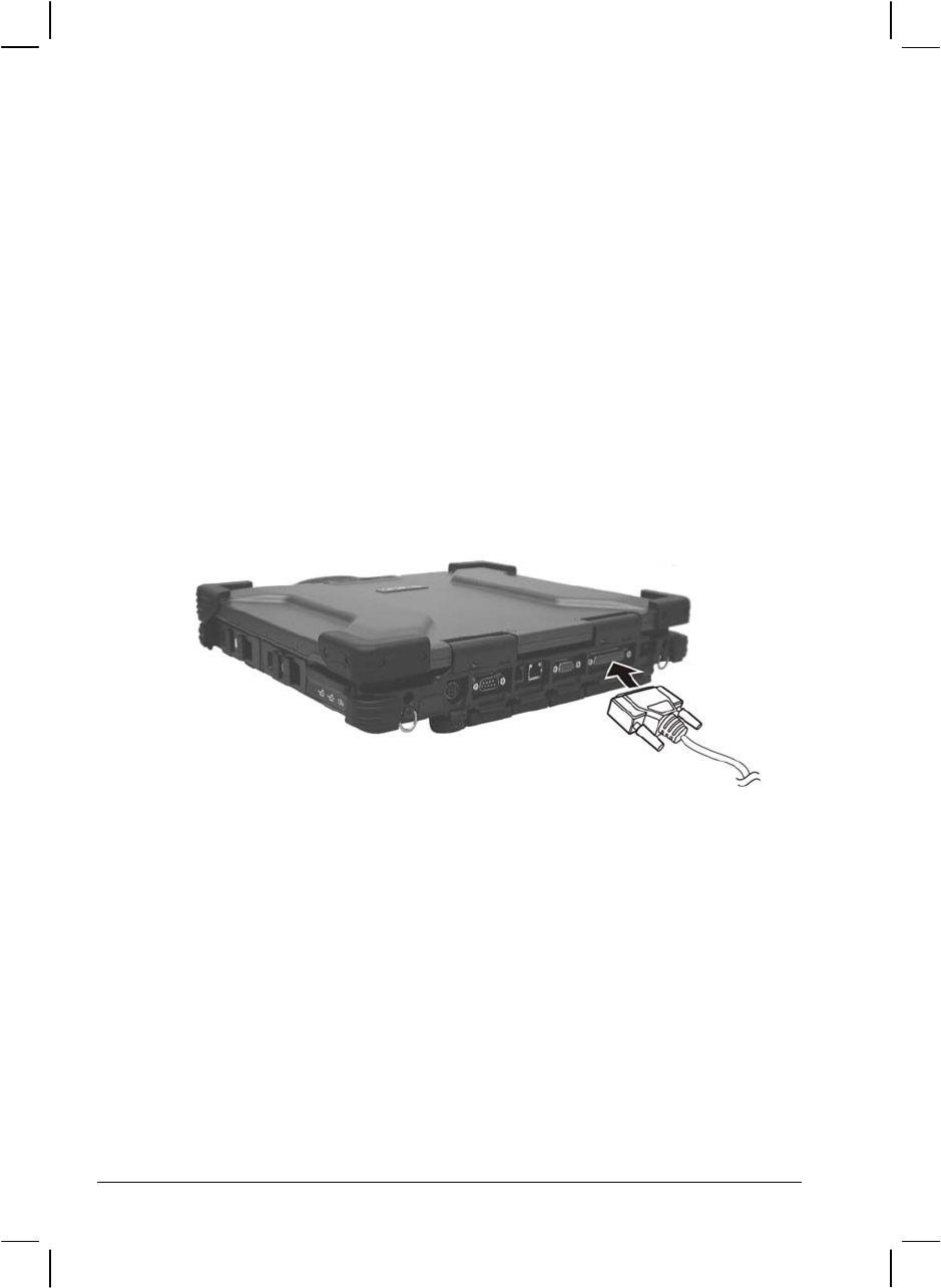
Connecting a Serial Device
Your computer has a serial port for connecting a serial device such as an
external modem.
Follow this procedure to connect a serial device:
1. Make sure the “Serial Port COM1” item is set properly in the SCU
program. (See “Advanced Menu” in Chapter 5 for information.)
2. Make sure the computer is not turned on.
3. Plug the device cable to the serial port on the rear of the computer.
4. Turn on the computer.
NOTE: Portable modems that derive power through the serial port cannot be used with
the computer. Instead, use a modem that is powered by its own internal battery or
external AC power.
Expanding Your Computer 4-5
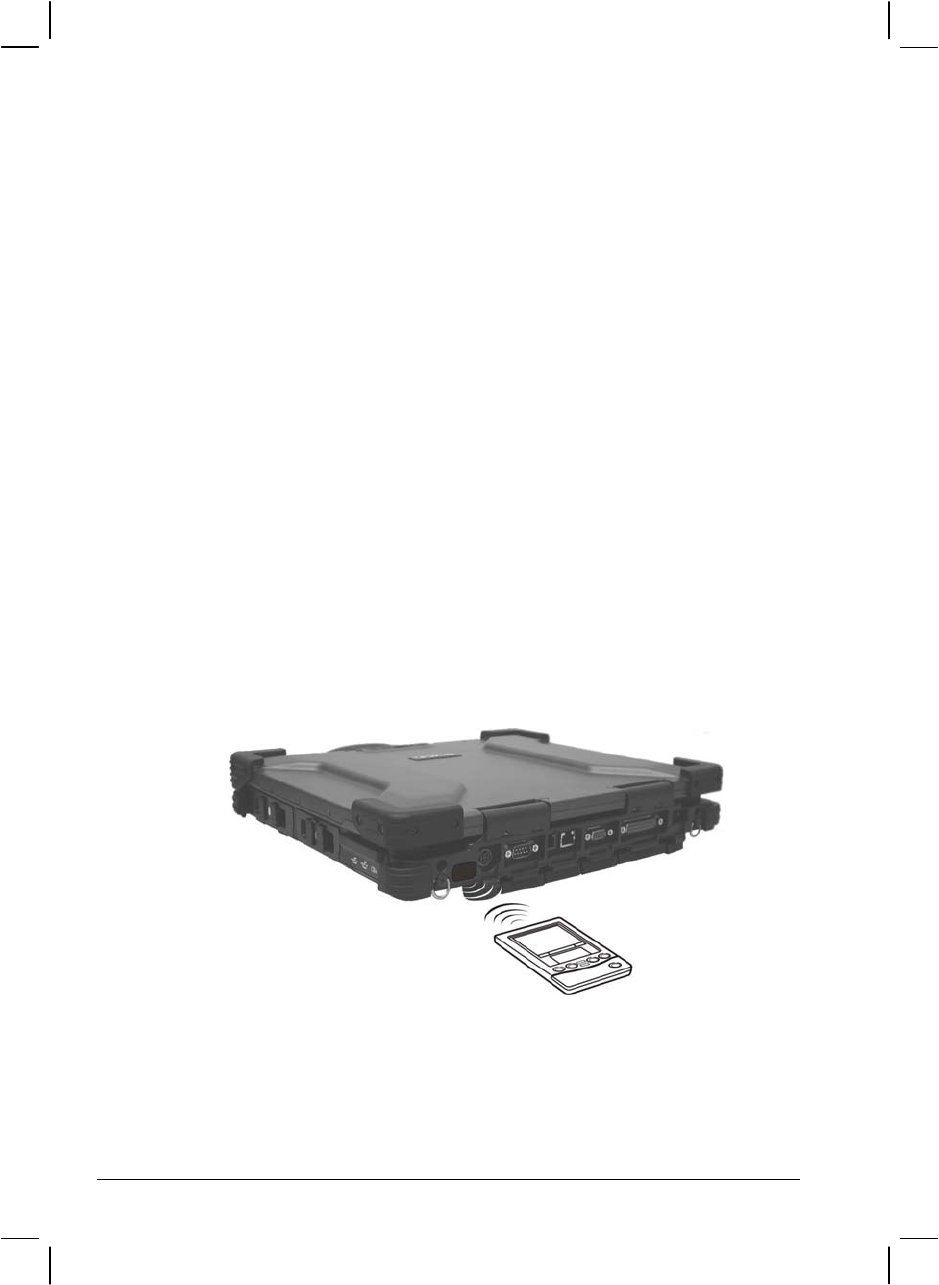
Connecting an IR Device
Your computer has an IR (infrared) port for connecting an
infrared-equipped device wirelessly such as another computer, printer, or
PDA (Personal Digital Assistant).
Follow this procedure to connect an IR device:
1. Make sure that the “Serial Port COM2 (FIR)” item is set properly in
the SCU program. (See “Advanced Menu” in Chapter 5 for
information.)
2. When using the IR port of your computer to receive data:
Place the transmitting device where its IR port faces the IR port of
your computer within the effective range − within ±20-degrees
vertical angle and within ±20-degrees horizontal angle at no greater
than 0.8~1.0 meter distance.
When using the IR port of your computer to transmit data:
Place the receiving device where the IR port of your computer faces
its IR port within the effective range − within ±15-degrees vertical
angle and within ±15-degrees horizontal angle at no greater than
0.8~1.0 meter distance.
To take advantage of the IR communications, you need a third party
software.
4-6 Expanding Your Computer

NOTE: During infrared communication, take note of the following:
Do not move the computer and IR device.
Do not enter Standby mode.
Do not use a cell phone or another IR device near the computer.
Avoid strong light such as sunlight or fluorescent light.
Disable the screen saver.
Expanding Your Computer 4-7
Connecting an IEEE 1394B Device
NOTE:
Your IEEE 1394B port will only function under Windows XP SP2. It is also Windows
Vista ready.
Make sure that the 1394B driver is installed correctly (see chapter 6 for details).
To connect an IEEE 1394A (also known as FireWire 400) device to the computer’s
IEEE 1394B (also known as FireWire 800) port, you need an optional FireWire
800/FireWire 400 bilingual cable.
Your computer has an IEEE 1394B port for connecting IEEE 1394B
devices.
IEEE 1394B is the next-generation serial bus standard, featuring
high-speed data transfer that doubles the throughput of the original IEEE
1394A interface (from 400 Mbit/sec to 800 Mbit/sec) and dramatically
increases the maximum distance of connections (up to 15 feet away,
while a FireWire 800 optical repeater will connect devices up to 1000
meters (3300 feet) away). It allows connection of up to 63 devices. The
applications include mass storage device, digital video (DV) camcorder,
or a digital audio device.
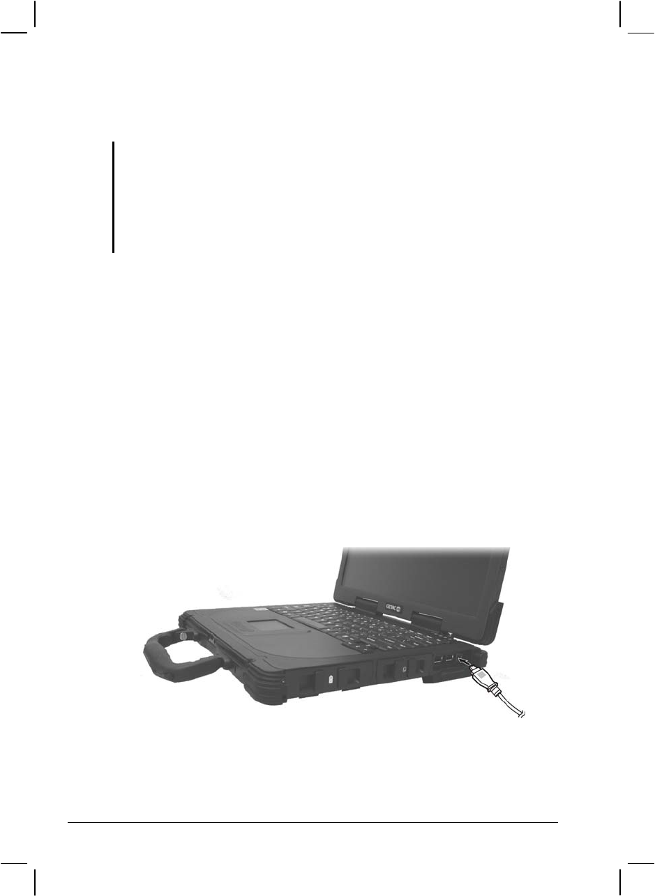
To connect an IEEE 1394B device, prepare an IEEE 1394B cable. Plug
the appropriate end of the cable to the computer’s IEEE 1394B connector
and the other end to the device’s corresponding connector.
4-8 Expanding Your Computer

Using PC Cards
Your computer has a PC card slot.
PC cards are credit card-sized peripheral products based on the standards
developed by PCMCIA (Personal Computer Memory Card International
Association). PCMCIA is a non-profit association for promoting the
interchangeability among mobile computers where ruggedness, low
power, and small size are critical.
PC Card Type
Your computer’s PC card slot can accommodate two type II card or one
type II card and one smart card (option). Typical type II cards are flash
memory, SRAM, modem, LAN, and SCSI cards.
CardBus Support
Your computer’s PC card slot supports CardBus specifications. CardBus
is the 32-bit version of PC card technology. It allows speeds of up to 133
Mbps at 33 MHz. Typical applications are SCSI host bus and high-speed
network cards.
Inserting and Removing a PC Card
NOTE:
Some PC cards require additional system resources. Before using such PC card,
you may have to free other system resources for the PC card.
Although some PC cards can be inserted and removed without turning off the
computer, you cannot remove or install PC cards during Standby mode.
To insert a PC card:
1. Locate the PC card slot on the right side of the computer.
Expanding Your Computer 4-9
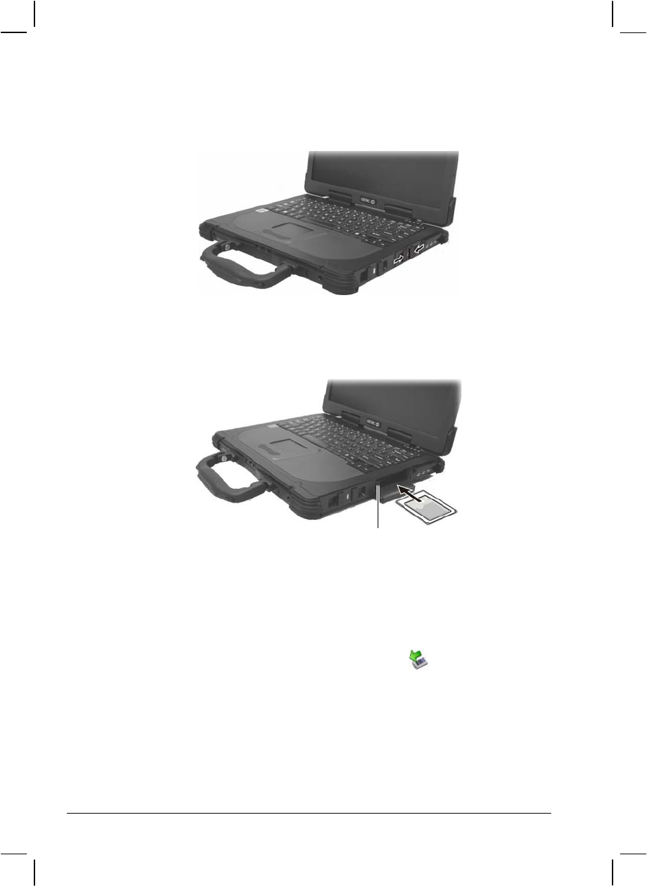
2. Open the PC card slot cover by pressing on both sides of the release
latch using your thumb and index fingers.
3. Slide the PC card, with its label facing up, into the slot until the eject
button pops out.
Eject Button
4. When a new card is seated, the computer will detect it and try to
install the appropriate driver. Follow the on-screen instructions to
complete the process.
To remove a PC card:
1. Double-click on the Safely Remove Hardware icon found on the
Windows XP taskbar and the Safely Remove Hardware window
appears on screen.
2. Select (highlight) the PC card from the list to disable the card.
3. Push the eject button and the card will slide out slightly.
4. Pull the card out of the slot.
4-10 Expanding Your Computer
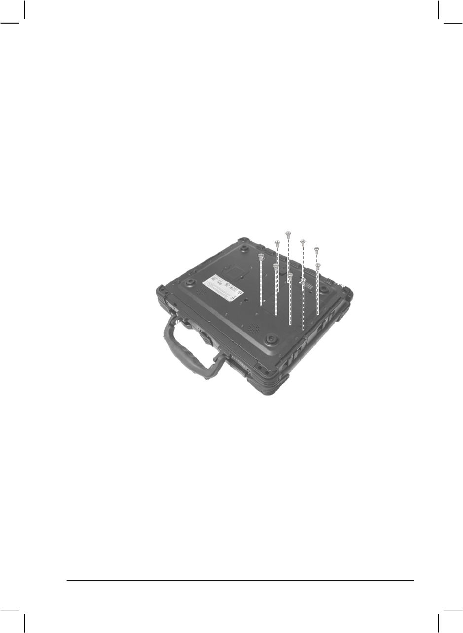
System Memory Upgrade
You can upgrade your computer by changing system memory to a
maximum of 2 GB on the two 200-pin 400/533 MHz DDR2 SO-DIMM
slots.
To install the SO-DIMM:
1. Carefully place the notebook computer upside down.
2. Remove the nine screws to detach the SO-DIMM compartment
cover.
Expanding Your Computer 4-11
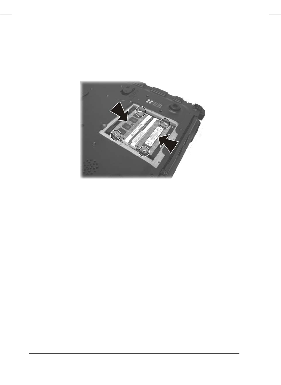
3. To install the SO-DIMM, match the SO-DIMM's notched part with
the socket's projected part and firmly insert the SO-DIMM into the
socket at a 20-degree angle. Then push down until the retaining clips
lock the SO-DIMM into position.
4. Replace the SO-DIMM compartment cover and secure with nine
screws.
4-12 Expanding Your Computer

CHAPTER 5
Setup Configuration Utility (SCU)
SCU is a program for configuring the BIOS (Basic Input/Output System)
settings of the computer.
BIOS is a layer of software, called firmware, that translates instructions
from other layers of software into instructions that the computer hardware
can understand. The BIOS settings are needed by your computer to
identify the types of installed devices and establish special features.
This chapter tells you how to use the SCU program.

When and How to Use the SCU Program
When to Use
You need to run the SCU program when:
You see an error message on the screen requesting you to run Setup.
You want to restore the factory default settings.
You want to modify some specific settings according to the
hardware.
You want to modify some specific settings to optimize system
performance.
Starting SCU
NOTE:
The Setup screens shown in this chapter are for your reference only. The actual
items or settings on your computer may differ.
The Setup program may have been updated after the publication of this manual.
The settings you select in your operating system might override similar settings in
Setup.
To run SCU, press F2 when the prompt appears in the lower left corner of
the screen during system startup. The prompt shows up on the screen for
only a few seconds. You must press F2 quickly. The SCU menu appears
as shown next.
5-2 Setup Configuration Utility (SCU)
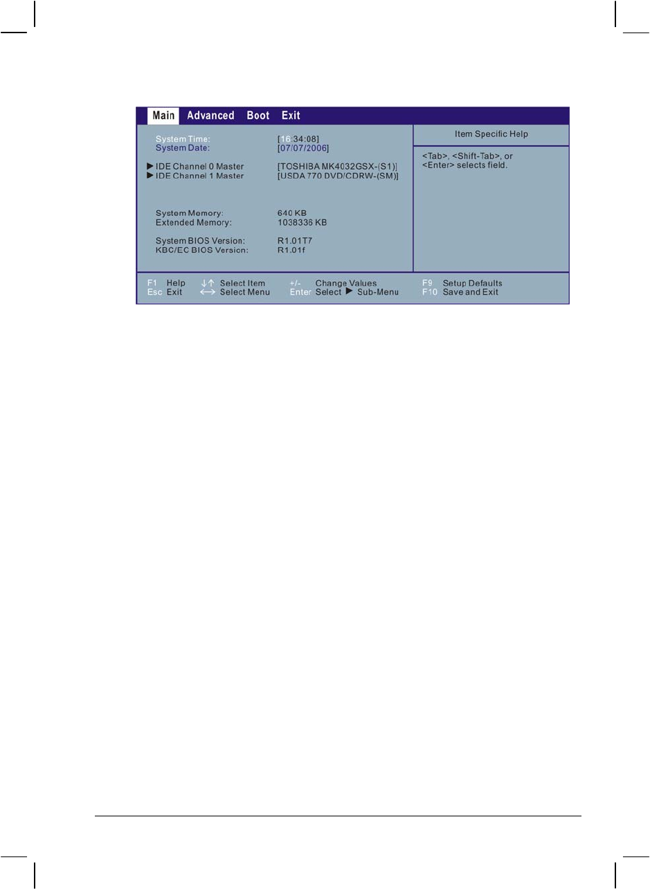
The SCU menu can be divided into four areas:
On the top is the menu bar containing the titles of the available
menus. Each menu title brings a specific menu.
The center column of the menu displays the current configuration
information of the system, devices, and memory items.
The right column of the menu provides more detailed information
when a menu item is highlighted.
On the bottom keyboard keys are displayed for navigating the screen.
Setup Configuration Utility (SCU) 5-3

Moving Around and Making Selections
In most cases, you must go through two levels to complete the setting for
an item: menu title and submenu.
Use the keyboard to move around and make selections. A brief
description of keyboard usage is listed next:
Key Function
← , → Selects a menu title.
↑ , ↓ Selects an item or option.
+, – Changes the value.
Enter 1) Brings up the sub-menu when available.
2) Opens or closes the option window when an item is selected.
Esc 1) Displays the Exit menu.
2) Closes the option window if one is open.
F1 Displays help information.
F9 Changes the values to the setup defaults.
F10 Saves and exit the SCU program.
5-4 Setup Configuration Utility (SCU)
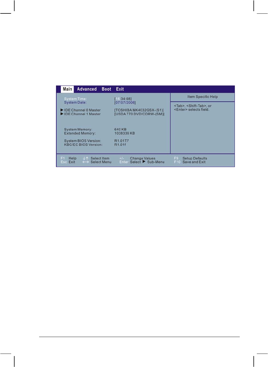
Main Menu
The Main menu contains the system date and time as well as the IDE
interface setting of the system.
System Time sets the system time.
System Date sets the system date.
IDE Channel 0/1 Master sets the type of storage device installed. The
options are User, Auto, CD-ROM, ATAPI Removable, None, IDE
Removable, and Other ATAPI.
Setup Configuration Utility (SCU) 5-5
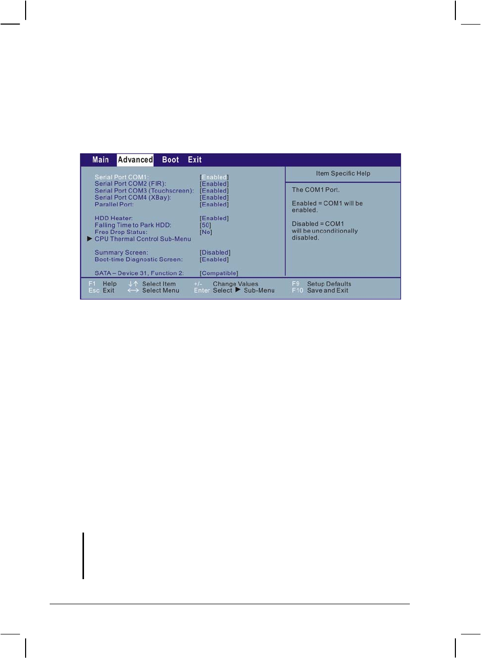
Advanced Menu
The Advanced menu contains the I/O (input/output) configuration
settings of the system.
Serial Port COM1 enables or disables the serial (COM1) port. The
options are Enabled and Disabled.
Serial Port COM2 (FIR) enables or disables the infrared (COM2) port.
The options are Enabled and Disabled.
Serial Port COM3 (Touchscreen) enables or disables the touchscreen
(COM3) function. The options are Enabled and Disabled.
Serial Port COM4 (XBay) enables or disables the XBay (COM4) port.
The options are Enabled and Disabled.
Parallel Port enables or disables the parallel port. The options are
Enabled and Disabled.
HDD Heater sets if the system automatically turns on the built-in hard
disk drive heater for low temperature operation. The options are Enabled
and Disabled.
NOTE:
To use the HDD heater feature, the MTCCTRL driver supplied with your computer
must be installed (see chapter 6 for details).
Disable this item to conserve energy when using battery power.
5-6 Setup Configuration Utility (SCU)

Falling Time to Park HDD sets the time (millisecond) for EC to inform
SMI to park the HDD during an accidental drop. The options are 0
(disabled) to 127.
Free Drop Status specifies if the computer had been free-dropped. The
options are Yes and No.
CPU Thermal Control Sub-Menu sets the items that control various
CPU thermal parameters.
Summary Screen sets if the system configuration would be displayed
onscreen during system boot-up. The options are Enabled and Disabled.
Boot-time Diagnostic Screen sets if the system diagnostic screen would
be displayed during system boot-up. The options are Enabled and
Disabled.
SATA – Device 31, Function 2 sets the primary/secondary
compatible/enhanced SATA/PATA (serial ATA / parallel ATA)
controller in Legacy/Native mode. The options are Compatible and
Enhanced.
Setup Configuration Utility (SCU) 5-7
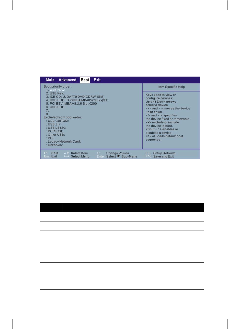
Boot Menu
The Boot menu sets the sequence of the devices to be searched for the
operating system.
The bootable devices will be automatically detected during POST and
shown here, allowing you to set the sequence that the BIOS uses to look
for a boot device from which to load the operating system.
A brief description of keyboard usage is listed next:
Key Function
↑ , ↓ Selects (highlight) a boot device.
+, – Changes the boot sequence.
1 to 4 Loads the default boot sequence.
f or r Specifies if the device is fixed (f) or removable (r).
X Moves the highlighted boot device from the “Boot priority order”
list to the “Excluded from boot order” list, and vice versa.
Shift + 1
Deactivates/activates the highlighted boot device on the “Boot
priority order” list. When a device has been deactivated, an “!”
(exclamation) symbol appears beside the item and system will
bypass it when detecting boot device during POST.
5-8 Setup Configuration Utility (SCU)
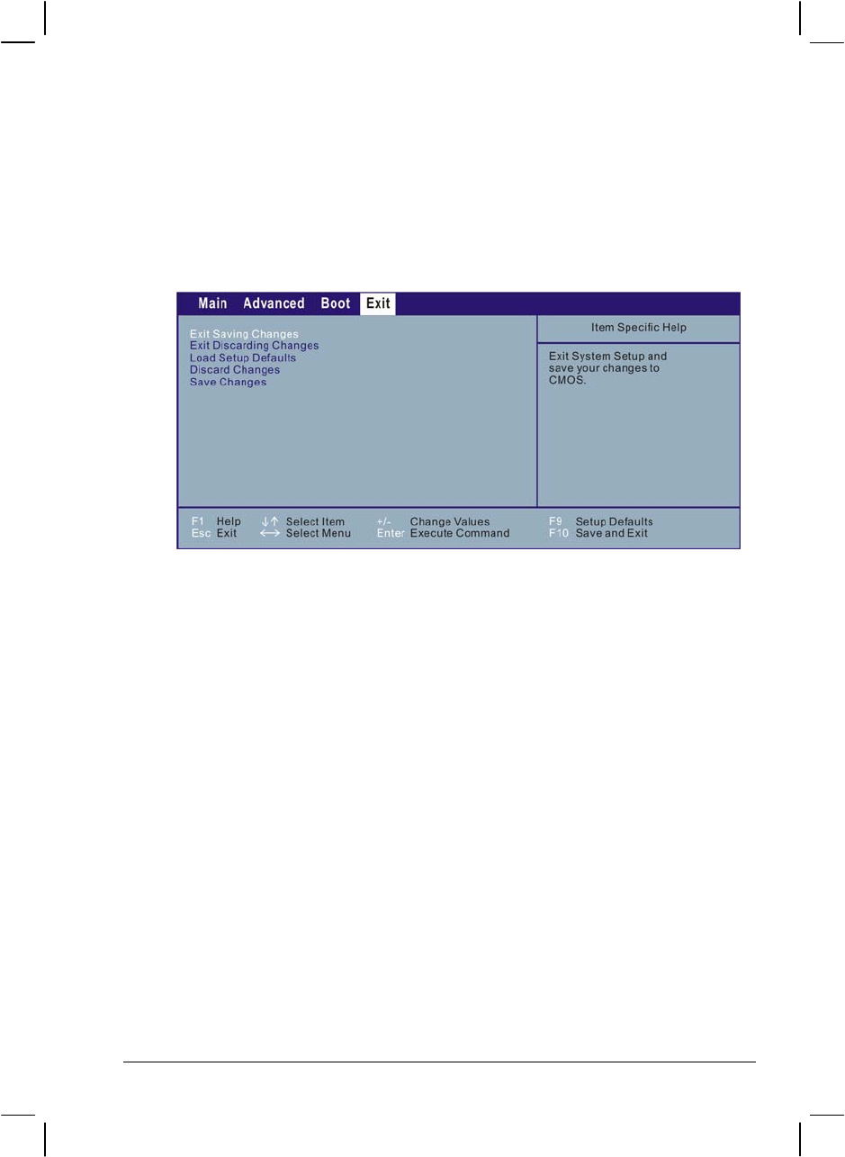
Exit Menu
The Exit menu displays ways of exiting the SCU program. After finishing
with your settings, you must save and exit so that the changes can take
effect.
Exit Saving Changes saves the changes you have made and exits BIOS
Setup Utility.
Exit Discarding Changes exits BIOS Setup Utility without saving the
changes you have made.
Load Setup Defaults loads the factory default values for all the items.
Discard Changes restores the previous values for all the items.
Save Changes saves the changes you have made.
Setup Configuration Utility (SCU) 5-9

5-10 Setup Configuration Utility (SCU)

CHAPTER 6
Installing Software Drivers
To take full advantage of the unique features of your computer, some
operating systems require custom software, known as drivers, to be
installed.
If you purchased the computer with Windows pre-installed, your dealer
may have already installed the drivers. If not, you need to install the
drivers using the driver disc supplied with your computer.
This chapter describes how to install the drivers.

How to Use the Driver CD
NOTE:
• The drivers may have been updated after this manual was published. For driver
upgrade, please contact your dealer.
• You can always find README or document files on the driver disc. These files
contain the latest information from the software supplier. Please read the files
together with this chapter.
• This driver disc supports Windows 2000 and Windows XP as well as Red-hat Linux
only. You are recommended to install Windows 2000 Service Pack 4 when using
Windows 2000 and Windows XP Service Pack 2 when using Windows XP.
• The available items may differ according to your computer model and operating
system.
• Please do not remove the driver disc when installing the driver.
An autorun program is provided on the driver disc to help you easily
install the drivers. As you insert the driver disc, the autorun program
automatically starts. If you need to start the program manually, run the
Autorun.exe program from the driver disc.
6-2 Installing Software Drivers
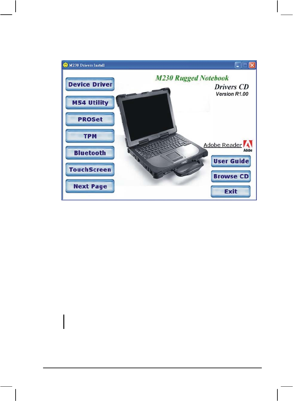
The main screen appears as shown next:
To install the necessary driver, just click on the particular option and
follow the onscreen instructions to continue and complete installation.
Drivers on the First Page
Device Driver Ensures the full function of the following drivers.
Install this main driver before installing the other
drivers. Upon clicking this button, the chipset, VGA,
audio, modem, and LAN drivers would be installed
one after the other.
M54 Utility Installs the optional ATi M54-CSP VGA controller
utility.
NOTE: You need to install the M54 utility if your system comes with the ATi M54-CSP
VGA controller and if you are using Windows XP Service Pack 2 only.
PROSet Installs the WLAN driver that allows your system to
connect wirelessly to the Internet.
Installing Software Drivers 6-3

TPM Allows you to use the TPM (Trusted Platform
Module) support for security.
Bluetooth Allows your computer to connect to
Bluetooth-compliant devices.
TouchScreen Allows you to use your fingers (or optional
touchscreen pen) as a pointing device on the LCD
screen (refer to the next section for further
instructions).
User Guide Allows you to view the Operation Manual on screen.
NOTE: You need Adobe Acrobat Reader to open the manual file supplied on this driver
disc. Install the Adobe Acrobat Reader program if you do not have it on your computer
by clicking on Adobe Reader.
Browse CD Browses the contents of the driver disc.
Exit Exits the driver installation.
6-4 Installing Software Drivers
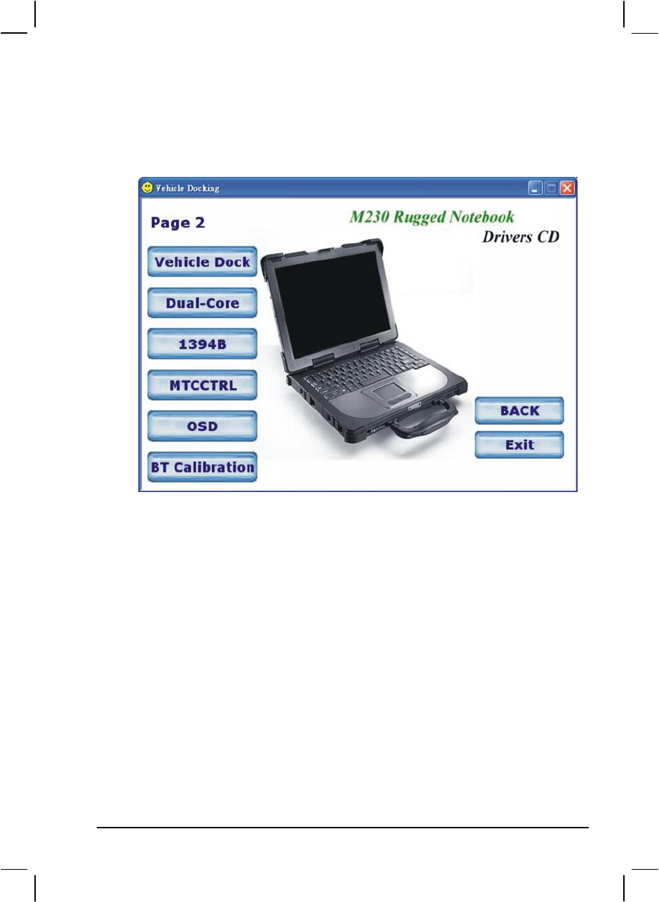
Drivers on the Second Page
Upon clicking on Next Page, the following screen appears.
Installing Software Drivers 6-5
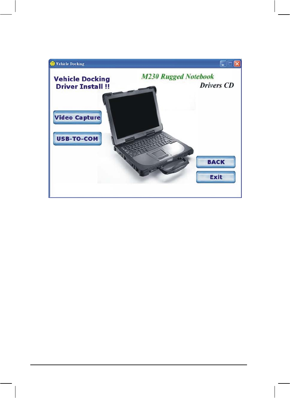
Vehicle Dock Upon clicking on this, the following screen appears.
Video Capture Allows you to connect a video capture device through
the AV input port (option).
USB-to-COM Allows you to use the optional wireless modem and
GPS features to transmit information wirelessly.
Dual Core Installs the dual core hotfix for Windows XP only.
1394B 1394B Please install the 1394 hot fix and note
that 1394B will be fully supported by Window
Vista .
This hotfix for Windows XP only.
MTCCTRL Allows you to use the built-in heater feature that
automatically turns on for low temperature hard disk
drive operation.
OSD Installs the OSD (on screen display) utility that
provides a graphic display to indicate the current
status of certain operations.
6-6 Installing Software Drivers

NOTE: The OSD utility is an option for you. You can decide whether you would like to
have this utility installed. (See the next section for details.)
BT Calibration Installs the battery pack automatic calibration utility.
NOTE: For Windows 2000 only.
Install the DirectX 8.1 driver to take full advantage of multimedia applications. Run the
file DX81NTeng.exe located on the /Utility/DirectX/ directory on your
driver disc.
Installing Software Drivers 6-7
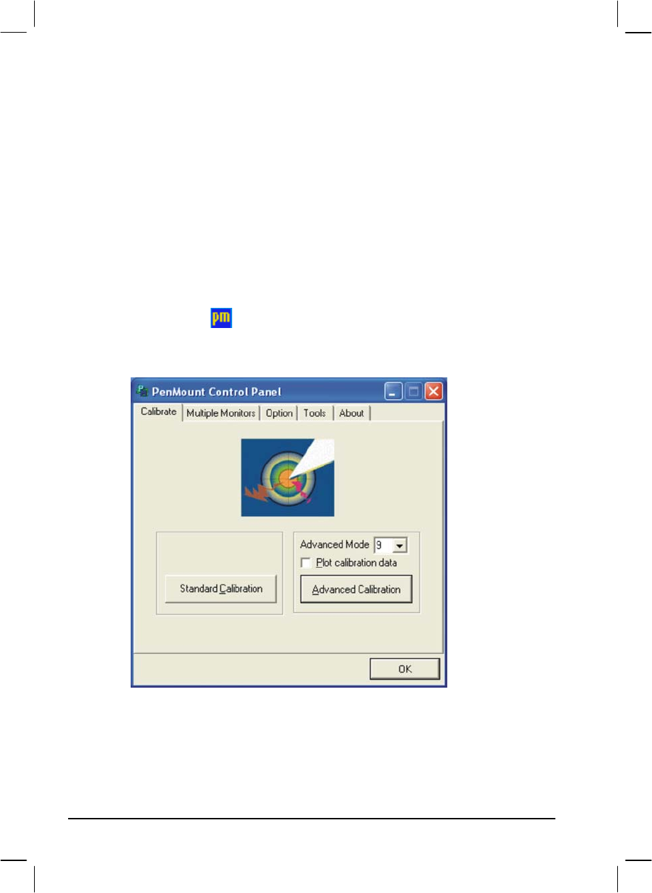
Touchscreen Driver
To install the touch screen driver, perform the following:
1. Insert the driver disc into the optical drive.
2. Click on TouchScreen and follow the onscreen instructions to
continue.
3. When finished installing, select Yes to reboot your system. The driver
should now be loaded.
4. After the system has finished rebooting, click on the PenMount
Monitor icon located on the taskbar to bring up the PenMount
Control Panel.
5. Click on Standard Calibration.
6. Click on the four sides (points) and the plus-sign “+” on the screen to
calibrate your touchscreen for use on the computer.
6-8 Installing Software Drivers
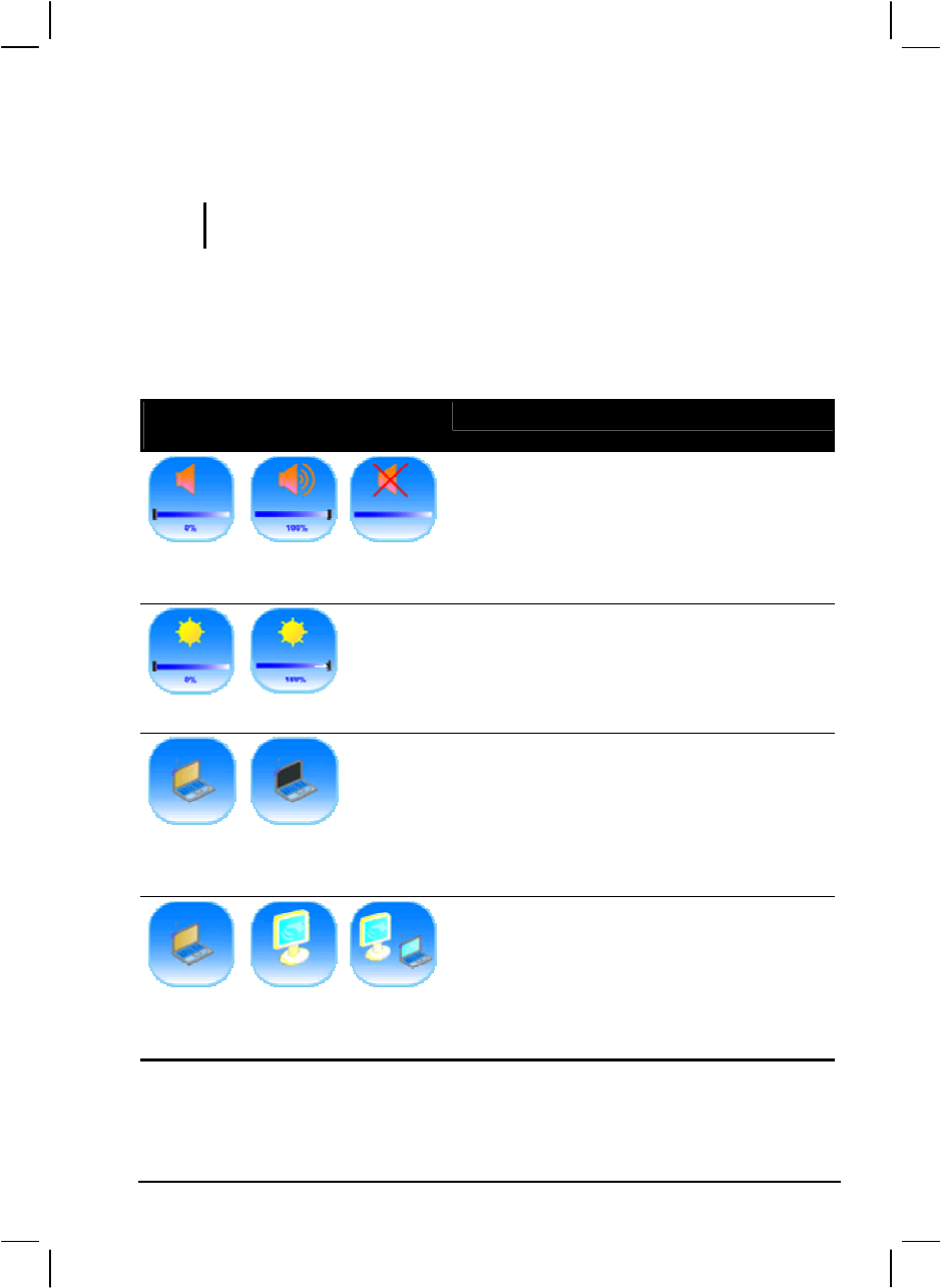
Using the OSD
NOTE: The OSD utility is an option for you. You can decide whether you would like to
have this utility installed.
With the OSD utility installed, the utility will be activated and an icon
will appear on the system tray every time Windows starts up.
A graphic display will appear on the screen to indicate the current status
of certain operations (as listed next).
Icon
Hot Key/Button Operation OSD Description
Fn+F3 Fn+F4 Mute
Icon appears on the screen whenever you
adjust Windows or any of its application
program’s volume control (e.g., Windows
Media Player, etc.) to indicate the volume
level. The OSD disappears after a few
seconds.
Fn+F5 Fn+F6
Icon appears on the screen to indicate the
brightness level. The OSD disappears after a
few seconds.
Fn+F7/F8 Fn+F7/F8
On Off
Icon appears on the screen to indicate that
LCD backlight (F7) or display (F8) is on or
off. The OSD disappears after a few seconds.
Fn+F9 Fn+F9 Fn+F9
LCD CRT Both
Icon appears on the screen to indicate the
current display output. The OSD disappears
after a few seconds.
Installing Software Drivers 6-9

Icon
Hot Key/Button Operation OSD Description
Fn+F11 Fn+F11
On Off
Icon appears on the screen to indicate that
wireless LAN is on or off. The OSD
disappears after a few seconds.
AC In AC out
Icon appears on the screen to indicate that AC
power cord has been connected or unplugged.
The OSD disappears after a few seconds.
Speaker On Speaker Off
Icon appears on the screen to indicate that
speaker is on or off. The OSD disappears after
a few seconds.
Exiting and Reactivating the OSD Utility
To exit the OSD utility, right-click on the OSD utility icon on Windows
system tray and click on “Exit.”
To reactivate the OSD utility:
Double-click on the file OSD.EXE located on
c:/Program Files/OSD/ or
Restart the system.
6-10 Installing Software Drivers

CHAPTER 7
Caring for the Computer
Taking good care of your computer will ensure a trouble-free operation
and reduce the risk of damage to your computer.
This chapter gives you guidelines covering these areas of maintenance:
How to protect the computer
What to note when using and storing the computer
How to clean the computer
What to note when using the battery pack
What to note when traveling with the computer
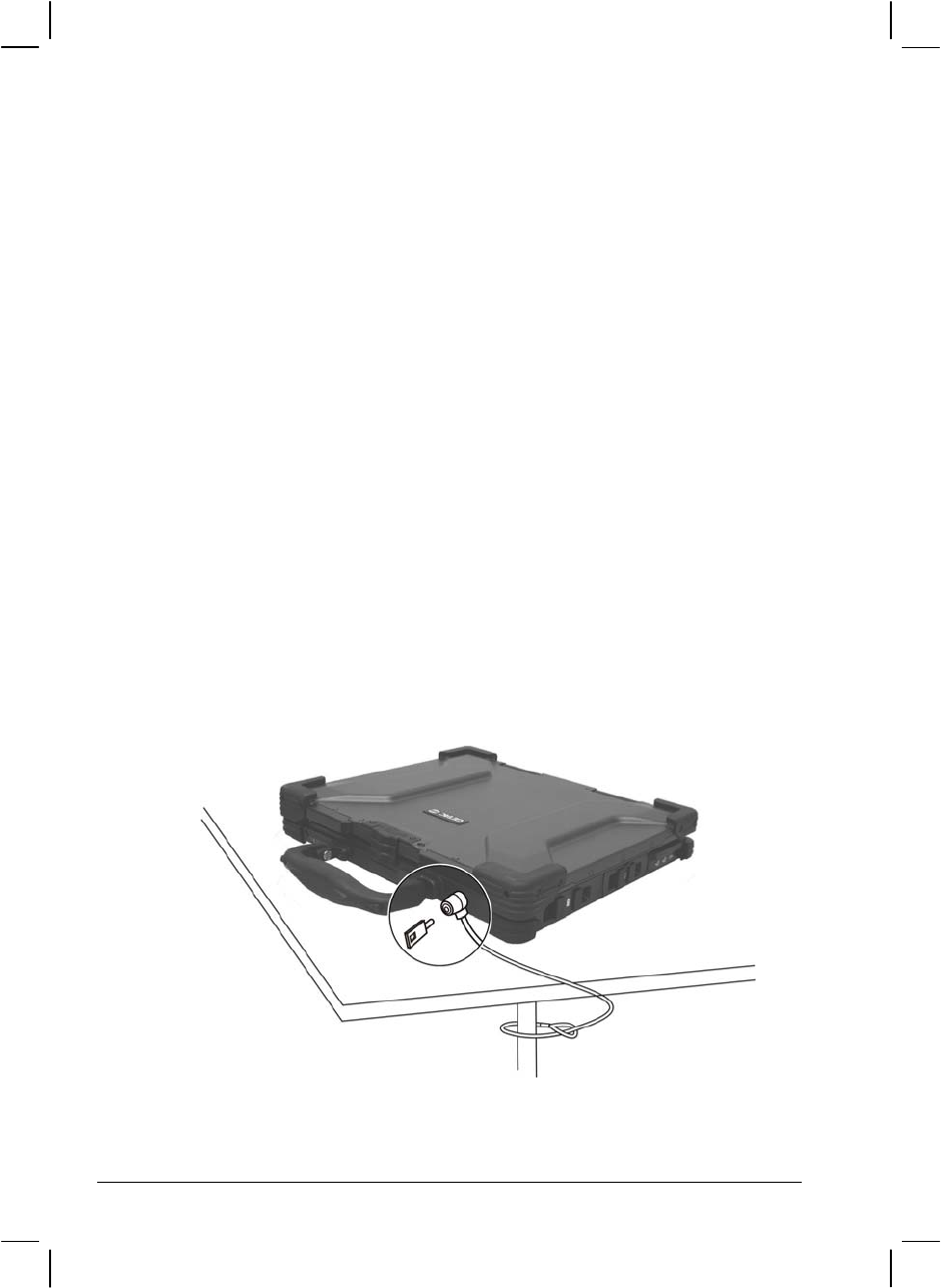
Protecting the Computer
To safeguard the integrity of your computer data as well as the computer
itself, you can protect the computer in several ways as described in this
section.
Using the Password
The power-on password protects your computer against unauthorized
use. If the password is set, the prompt requesting for the password
appears on the screen whenever the computer is turned on.
Using the Cable Lock
You can use a Kensington-type cable lock to protect your computer
against theft. The cable lock is available in most computer stores.
To use the lock, loop the lock cable around a stationary object such as a
table. Insert the lock to the Kensington lock hole and turn the key to
secure the lock. Store the key in a safe place.
7-2 Caring for the Computer

Using an Anti-Virus Strategy
New viruses are always being developed nowadays and they are attacking
computers even more easily with emails so commonly used worldwide.
You can also install a virus-detecting program to monitor potential
viruses that could damage your files.
Caring for the Computer 7-3

Taking Care of the Computer
Location Guidelines
Use the computer where the temperature is between 0 °C (32 °F) and
55 °C (131 °F).
Avoid placing the computer in a location subject to high humidity,
extreme temperatures, mechanical vibration, direct sunlight, or heavy
dust.
Do not cover or block any ventilation openings on the computer. For
example, do not place the computer on a bed, sofa, rug, or other
similar surface. Otherwise, overheating may occur that results in
damage to the computer.
Keep the computer at least 13 cm (5 inches) away from electrical
appliances that can generate a strong magnetic field such as a TV,
refrigerator, motor, or a large audio speaker.
Do not move the computer abruptly from a cold to a warm place. A
temperature difference of more than 10 °C (18 °F) will cause
condensation inside the unit, which may damage the storage media.
Do not place the computer on an unsteady surface.
General Guidelines
Do not place heavy objects on top of the computer as this may
damage the display.
The screen surface is easily scratched. Do not use paper towels to
clean the display. Avoid touching it with a ballpoint pen or pencil.
To maximize the life of the backlight in the display, allow the
backlight to automatically turn off as a result of power management.
Avoid using a screen saver or other software that prevents the power
management from working.
7-4 Caring for the Computer

Cleaning Guidelines
Never clean the computer with its power on.
Use a soft cloth moistened with water or a non-alkaline detergent to
wipe the exterior of the computer.
Gently wipe the display with a soft, lint-free cloth. Do not use alcohol
or detergent on the display.
Dust on the IR port can interfere with data transfer. Wipe the port
with a soft, dry cloth.
Dust or grease on the touchscreen can affect its sensitivity. Clean the
touchscreen by using adhesive tape to remove the dust and grease on
its surface.
Battery Pack Guidelines
Recharge the battery pack when it is nearly discharged. When
recharging, make sure the battery pack is fully charged. Doing so
may avoid harm to the battery pack.
Operate the computer with the battery pack installed even when using
external power. This ensures that the battery is fully charged.
If you will not be using the computer for a long period of time (more
than two weeks), remove the battery pack from the computer.
If you remove the battery pack, make sure the battery terminals do
not contact any conductors such as metal objects or water. Otherwise,
the battery may become unusable as a result of a short circuit.
If you need to store the battery pack, store it in a cool, dry place.
Never allow the temperature to exceed 70 °C (158 °F).
Do not leave the battery pack in storage for more than 3 months
without recharging it.
Caring for the Computer 7-5

When Traveling
Before traveling with your computer, make a backup of your hard
disk data into USB disks or other storage devices. As an added
precaution, bring along an extra copy of your important data.
Make sure the battery pack is fully charged.
Make sure the computer is turned off.
Do not leave objects that will press onto the display.
Disconnect the AC adapter from the computer and take it with you.
Use the AC adapter as the power source and as a battery-charger.
Hand-carry the computer. Do not check it in as luggage.
Allow extra time for airport security. Many airports inspect
electronic devices carefully.
If you need to leave the computer in the car, put it in the trunk of the
car to avoid exposing the computer to excessive heat.
When going through airport security, it is recommended that you
send the computer and USB disk through the X-ray machine (the
device you set your bags on). Avoid the magnetic detector (the device
you walk through) or the magnetic wand (the hand-held device used
by security personnel).
If you plan to travel abroad with your computer, consult your dealer
for the appropriate AC power cord for use in your country of
destination.
7-6 Caring for the Computer

CHAPTER 8
Troubleshooting
Hardware, software, or a combination of both can cause computer
problems. When you encounter any problem, it might be a typical
problem that can easily be solved.
This chapter tells you what actions to take when solving common
computer problems. It is divided into three sections:
Preliminary checklist
Solving common problems
Resetting the computer

Preliminary Checklist
Here are helpful hints to follow before you take further actions when you
encounter any problem:
Try to isolate which part of the computer is causing the problem.
Make sure that you turn on all peripheral devices before turning on
the computer.
If an external device has a problem, make sure that the cable
connections are correct and secure.
Make sure that the configuration information is properly set in the
SCU program.
Make sure that all the device drivers are correctly installed.
Make notes of your observations. Are there any messages on the
screen? Do any indicators light? Do you hear any beeps? Detailed
descriptions are useful to the service personnel when you need to
consult one for assistance.
If any problem persists after you follow the instructions in this chapter,
contact an authorized dealer for help.
8-2 Troubleshooting

Solving Common Problems
For easy reference, the problems are divided into these categories.
Problem Type Go to
Battery Problems P. 8-4
Bluetooth Problems P. 8-4
Optical Drive Problems P. 8-4
Display Problems P. 8-5
Hardware Device Problems P. 8-7
Hard Disk Drive Problems P. 8-7
Infrared Problems P. 8-8
Keyboard, Mouse and Touchpad Problems P. 8-8
LAN Problems P. 8-9
WLAN Problems P. 8-9
Modem Problems P. 8-9
PC Card Problems P. 8-11
Power Management Problems P. 8-11
Printer Problems P. 8-12
Software Problems P. 8-13
Sound Problems P. 8-13
Startup Problems P. 8-14
Other Problems P. 8-15
Troubleshooting 8-3

Battery Problems
The battery does not charge (Battery Charge indicator does not light
amber).
Make sure that the AC adapter is properly connected.
Make sure that the battery is not too hot. Allow time for the battery
pack to return to room temperature.
Make sure that the battery pack is installed correctly.
Make sure that the battery terminals are clean.
The operating time of a fully charged battery becomes shorter.
If you often partially recharge and discharge, the battery might not be
charged to its full potential. Initialize the battery to solve the problem.
(See “Initializing the Battery Pack” in Chapter 3 for instructions.)
The battery operating time indicated by the battery meter does not
match the actual operating time.
The actual operating time can be different from the estimated time,
depending on how you are using the computer. If the actual operating
time is much less than the estimated time, initialize the battery. (See
“Initializing the Battery Pack” in Chapter 3 for instructions.)
Bluetooth Problems
I cannot connect to another Bluetooth-enabled device.
Make sure that the Bluetooth driver is installed correctly.
Make sure that both devices have activated Bluetooth.
Make sure that the distance between the two devices are not over 10
meters or that there are no walls or other obstructions between the
devices.
Make sure that the other device is not in “Hidden” mode.
Make sure that both devices are compatible.
8-4 Troubleshooting
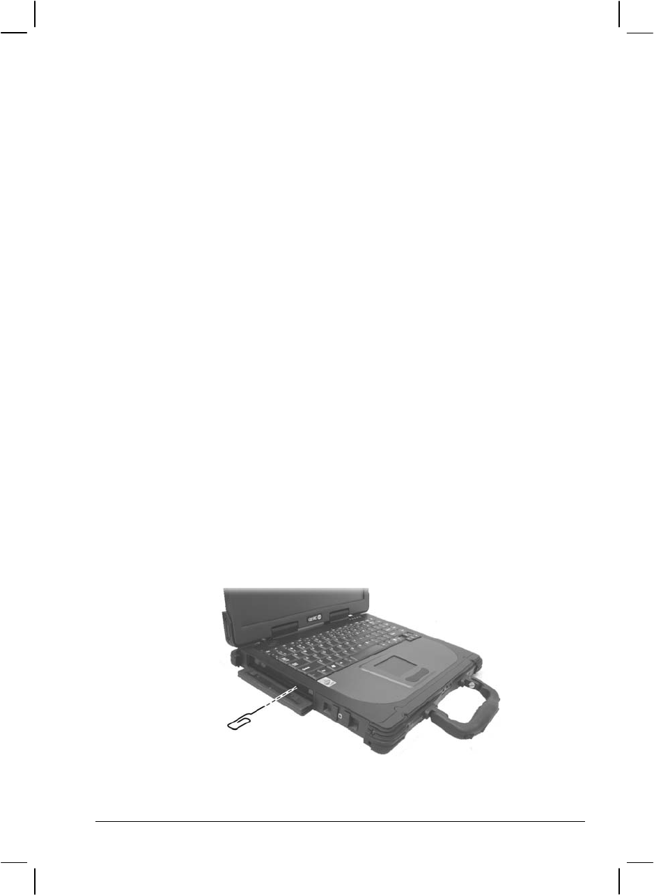
I cannot end a Bluetooth connection.
If another device is connected to your computer, you can either end
the connection using the other device or by deactivating Bluetooth.
Optical Drive Problems
The optical drive cannot read a disc.
Make sure that the disc is correctly seated in the tray, with the label
facing up.
Make sure that the disc is not dirty. Clean the disc with a disc cleaning
kit, available in most computer stores.
Make sure that the optical drive driver is installed correctly.
Make sure that the computer supports the disc or the files contained.
You cannot eject a disc.
The disc is not properly seated in the drive. Manually release the disc
following the method described next:
1. Turn off the system.
2. Insert a small rod, such as a straightened paperclip, into the drive’s
manual eject hole and push firmly to release the tray.
3. Pull the tray out until fully extended, and then remove the disc.
Troubleshooting 8-5

Display Problems
Nothing appears on the screen.
If the power-on indicator is not on, check the electrical outlet, the
plugs and power cords.
If the power button does not respond to a light touch, press the button
firmly.
If you are using battery power, make sure that it has a charge
remaining and that it is installed correctly.
During operation, the screen may automatically turn off as a result of
power management. Press any key to see if the screen comes back.
The brightness level might be too low. Increase brightness by pressing
Fn+F6.
The display output might be set to an external device. To switch the
display back to the LCD, press Fn+F9, or change the display through
the settings in Display Properties.
Reset the computer by pressing Ctrl+Alt+Del keys.
Try turning the computer off, wait for a few seconds, then turn it back
on.
The characters on the screen are dim.
Adjust the brightness and/or contrast.
Bad dots appear on the display at all times.
A small number of missing, discolored, or bright dots on the screen
are an intrinsic characteristic of TFT LCD technology. It is not
regarded as a LCD defect. The Inspection Standard generally agreed
in the LCD industry allows a maximum of 8 bad dots on a unit.
Resolution cannot be adjusted to desired setting.
Make sure that the device driver is installed correctly.
The external monitor displays nothing.
Make sure that the monitor is turned on.
8-6 Troubleshooting

Make sure that the monitor’s signal cable is properly connected.
Switch the display to the monitor by pressing Fn+F9, or change the
display through the settings in Display Properties.
Simultaneous display/multi-display does not work.
Make sure that you turn on the external monitor before turning on the
computer.
Press Fn+F9 to toggle through the display options or change the
settings in Display Properties in Windows.
Hardware Device Problems
The computer does not recognize a newly installed device.
The device may not be correctly configured in the SCU program. Run
the SCU program to identify the new type.
Make sure if any device driver needs to be installed. (Refer to the
documentation that came with the device.)
Make sure if the device needs any jumper or switch settings. (Refer to
the documentation that came with the device.)
Check the cables or power cords for correct connections.
For an external device that has its own power switch, make sure that
the power is turned on.
Hard Disk Drive Problems
The hard disk drive error message appears on the screen.
Insert a bootable diskette or CD disc and check the integrity of your
hard drive.
The hard disk drive has defects. Ask your dealer for help.
The hard disk drive operations seem slow.
The data files stored on the hard disk drive may be fragmented. Use a
tool such as Window’s Disk Defragmenter to defragment the files.
Troubleshooting 8-7

The hard disk drive in-use indicator glows without blinking.
The data files stored on the hard disk drive may be fragmented. Use a
tool such as Window’s Disk Defragmenter to defragment the files.
Infrared Problems
The IR port does not work.
Make sure that the IR ports of the two device face each other within a
±15-degrees angle and 1 meter (3 feet) distance and there are no
obstructions in between.
Make sure that the device connected is using an equivalent speed.
Make sure that the IR port is set correctly in the SCU program.
If you are printing to an infrared printer, make sure that the
appropriate driver is installed.
If you are using any file transfer functions, make sure that both the
computer and the IR device have the appropriate software running.
Make sure that there is no device radiating infrared rays, such as
remote-controlled devices or wireless headphones, near the computer
or device.
Make sure that no direct sunlight or fluorescent lamps are near the
computer or device.
Make sure that the IR ports are clean.
Keyboard, Mouse and Touchpad Problems
The keyboard does not respond.
Try connecting an external keyboard. If it works, contact an
authorized dealer, as the internal keyboard cable might be loose.
The numeric keypad is disabled.
Make sure that Num Lk is switched on. (Check if the Num Lock
Indicator
N
glows or not.)
8-8 Troubleshooting

The external keyboard does not work.
Make sure that the keyboard cable is properly connected.
The USB mouse does not work.
Make sure that the mouse cable is properly connected.
The touchpad does not work, or the pointer is difficult to control
with the touchpad.
Make sure that the touchpad is clean.
LAN Problems
I cannot access the network.
Make sure that the device driver is correctly installed.
Make sure that the LAN cable is properly connected to the RJ-45
connector and the network hub.
Make sure that the network configuration is appropriate.
Make sure that the user name or password is correct.
WLAN Problems
I cannot use the WLAN feature.
Make sure that the necessary driver(s) is correctly installed.
Make sure that the WLAN feature is turned on.
Transmission quality is poor.
Your computer may be in an out-of-range situation. Move your
computer closer to the Access Point or another WLAN device it is
associated with.
Check if there is high interference around the environment and solve
the problem as described next.
Troubleshooting 8-9

Radio interference exists.
Move your computer away from the device causing the radio
interference such as microwave oven and large metal objects.
Plug your computer into an outlet on a different branch circuit from
that used by the affecting device.
Consult your dealer or an experienced radio technician for help.
I cannot connect to another WLAN device.
Make sure that the WLAN feature is turned on.
Make sure that the SSID setting is the same for every WLAN device
in the network.
Your computer is not recognizing changes. Restart the computer.
Make sure that the IP address or subnet mask setting is correct.
I cannot communicate with the computer in the network when
Infrastructure mode is configured.
Make sure that the Access Point your computer is associated with is
powered on and all the LEDs are working properly.
If the operating radio channel is in poor quality, change the Access
Point and all the wireless station(s) within the BSSID to another radio
channel.
Your computer may be in an out-of-range situation. Move your
computer closer to the Access Point it is associated with.
Make sure that your computer is configured with the same security
option (encryption) to the Access Point.
Use the Web Manager/Telnet of the Access Point to check whether it
is connected to the network.
Reconfigure and reset the Access Point.
I cannot access the network.
Make sure that the necessary driver(s) is correctly installed.
Make sure that the network configuration is appropriate.
8-10 Troubleshooting

Make sure that the user name or password is correct.
You have moved out of range of the network.
Turn off power management.
Modem Problems
The modem does not work.
Make sure that the device driver is correctly installed.
Make sure that the COM port in the communication software is
correctly set.
Turn off power management.
PC Card Problems
The PC card does not work.
Make sure that the PC card is correctly seated.
If the card requires an IRQ (Interrupt ReQuest), make sure that there
is one available.
The PC card stops communicating properly.
The application may have been reset when the computer is turned off
or in Standby mode. Exit and restart the application.
Power Management Problems
The computer does not enter Standby or Hibernation mode
automatically.
If you have a connection to another computer, the computer does not
enter Standby or Hibernation mode if the connection is actively in
use.
Make sure that the Standby or Hibernation time-out is enabled.
Troubleshooting 8-11

The computer does not enter Standby or Hibernation mode
immediately.
If the computer is performing an operation, it normally waits for the
operation to finish.
The computer does not resume from Standby or Hibernation mode.
The computer automatically enters Standby or Hibernation mode
when the battery pack is empty. Do any one of the following:
− Connect the AC adapter to the computer.
− Replace the empty battery pack with a fully charged one.
The computer does not enter Hibernation mode with the Fn+F10 hot
keys.
Make sure that the Hibernation function is specified for the sleep
button.
Printer Problems
The printer does not work.
Make sure that the printer is turned on (if it comes with an
independent power source) and is online (ready to use).
Make sure that the printer’s signal cable is properly connected.
Make sure that the printer driver is correctly installed.
Make sure that you have assigned the printer port correctly in your
operating system or application program.
Make sure that the printer port is enabled in the SCU program.
The printer prints garbled information.
Make sure that the printer driver is correctly installed.
Make sure that the printer cable is properly connected.
8-12 Troubleshooting

Software Problems
An application program does not work correctly.
Make sure that the software is correctly installed.
If an error message appears on the screen, consult the software
program’s documentation for further information.
If you are sure the operation has stop, reset the computer. (See
“Resetting the Computer” later in this chapter.)
Sound Problems
No sound is produced.
Make sure that the volume control is not set too low.
Make sure that the device driver is correctly installed.
Make sure that the computer is not in Standby mode.
If using an external speaker, make sure that the speaker is properly
connected.
Distorted sound is produced.
Make sure that the volume control is not set too high or too low. In
most cases, a high setting can cause the audio electronics to distort the
sound.
The sound system does not record.
Adjust the playback or recording sound levels.
The external microphone or audio device does not work.
Make sure that the microphone is connected to the proper connector
on the computer.
Make sure that your computer is equipped with the driver needed.
Click the speaker symbol on the taskbar and check the Windows
volume control.
Check the volume control of your computer.
Troubleshooting 8-13

Startup Problems
When you turn on the computer, it does not respond and the Power
Indicator does not light green.
If you are using an external AC power, make sure that the AC adapter
is correctly and securely connected. If so, make sure that the electrical
outlet works properly.
If you are using the battery power, make sure that the battery is not
discharged.
When you turn on the computer, it stops after POST.
Restart your computer.
The message “Operating system not found” appears on the
screen after you turn on the computer.
If this message appears when you are booting from the hard disk,
insert a bootable disc in the optical drive and check the condition of
the hard disk.
Make sure that the hard disk is recognized correctly in the SCU
program.
The message “Invalid
system disk” or “Disk error” appears
on the screen after you turn on the computer.
If you are deliberately trying to boot from a CD disc, replace the disc
with a bootable one and press any key to continue booting.
If you are booting from the hard disk, make sure that there is no CD
disc in the optical drive. If there is, remove it and restart the system.
If this message appears when you are booting from the hard disk,
insert a bootable disc in the optical drive and check the condition of
the hard disk.
Make sure that the hard disk is set correctly in the SCU program.
8-14 Troubleshooting

Other Problems
The date/time is incorrect.
Correct the date and time via the operating system or SCU program.
After you have performed everything as described above and still
have the incorrect date and time every time you turn on the computer,
the RTC (Real-Time Clock) battery is at the end of its life. Call an
authorized dealer to replace the RTC battery.
Troubleshooting 8-15

Resetting the Computer
You may have to reset (reboot) your computer on some occasions when
an error occurs and the program you are using hangs up.
If the system operation seems to hang up, first wait. It is possible that the
system is processing data. Periodically check the hard disk drive in-use
indicator, if it flashes irregularly, the program may be accessing data and
preventing you from using the keyboard. If you are sure the operation has
stopped and you cannot use the “restart” function of the operating system,
reset the computer.
Reset the computer by any one of these methods:
Press Ctrl+Alt+Del.
If the above action does not work, turn off the system. Wait for at least
five seconds and turn it on again.
CAUTION: Resetting will cause any unsaved data to be lost.
8-16 Troubleshooting
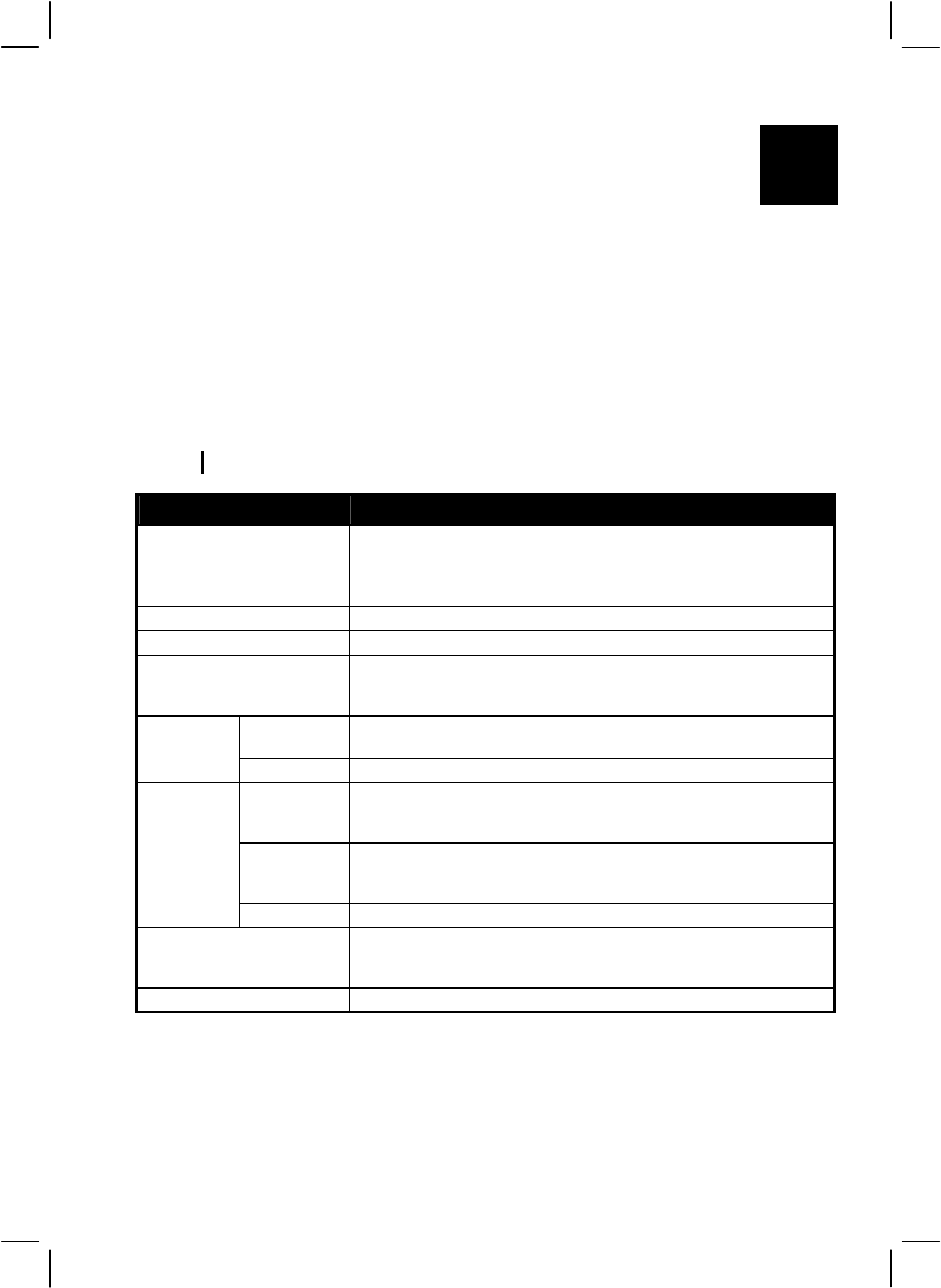
A
APPENDIX
Specifications Specifications
NOTE: Specifications are subject to change without any prior notices. NOTE: Specifications are subject to change without any prior notices.
Parts Specifications
CPU Intel Yonah low voltage dual core processor µ-FCBGA package
1.66 GHz
Intel Yonah low voltage dual core processor µ-FCBGA package 1.5 GHz
667 MHz Front Side Bus (FSB), 15 W thermal ceiling
Core logic Intel 945GM chipset (Calistoga) + ICH7-M (PCI express × 6 channels)
Cache memory L2 2 MB on-die
ROM BIOS 8 MB Flash EEPROM (includes system and VGA BIOS), Plug-&-Play,
ACPI 2.0 capability, boot from IDE/SATA devices and USB
optical/floppy drive, Suspend-to-DRAM/HDD, PC2001 compliance
System Two 200-pin DDR2 SO-DIMM sockets,400/533 MHz
maximum 2 GB (standard 256 MB)
RAM
Video 64 MB (shared system memory)
Panel 14.1-inch TFT XGA LCD, resolution up to 1024×768,
15-inch TFT SXGA+ LCD, resolution up to 1400×1050
Touchscreen (option), high-contrast display (option for 14.1-inch LCD)
Video
controller Integrated in Intel 945GM chipset, Intel GMA950, or
ATi M54-CSP VGA controller with 128 MB memory (option)
dual view function, LCD/CRT simultaneous display capability
Display
Video port VGA port
Keyboard Waterproof membrane cover
Waterproof rubber keyboard (option)
Rubber keyboard with backlight feature (option)
Pointing device Touchpad with two buttons, waterproof and resistance-type (option)
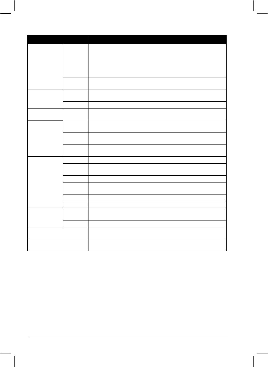
Parts Specifications
Hard disk
drive bay SATA, easily removable for maintenance,
optional built-in heater for low temperature support (–20 0C~55 0C),
optional low temperature 20 GB without heater
Built-in protection to support free drop from 0 to 3 feet in operating mode:
1~3 feet drop protected by G-sensor
0~1 foot drop protected by special resistant-designed construction
Storage device
Optical
drive bay Easily swappable bay for slim-type CD/Combo/DVD dual drive, or
second battery
Audio
controller Azalia 32-bit 192 kHz AC97 codec Rev.2.3 support,
two built-in 2-watts stereo speakers
Audio
Audio port Two audio ports for Mic-in / Line-out
PC card Type II × 2 or Type II × 1 and built-in smart card reader × 1,
CardBus support
On right
side X-Bay, two USB ports (supports system boot-up from optical drive), one
IEEE 1394B port or PS/2 port (option)
On rear
side IR port, serial port, RJ-11 port, RJ-45 port, parallel port
I/O ports
On
underside Docking port (POGO) supports hot docking
LAN 10/100/1000Base-T Ethernet with TPM security function
Wireless
modem
SIERRA, Model: MC8775V
Modem 56 kbps MDC
GPS GPS module with built-in antenna – option
Communication
AC adapter Input: 100∼240 V AC, 50∼60 Hz AC auto-sensing/switching
Output: 90 W Universal or above
Power
Battery Li-ion battery 7200 mAh / 11.1 V
Dimension (W×D×H) 12.9×10.7×1.8 inch (328×272.1×46 mm) for 14.1-inch model
13.3×11.3×1.8 inch (338×286×46 mm) for 15-inch model
Weight Less than 9.3 lb (4.2 kg) for 14.1-inch model
Less than 9.7 lb (4.4 kg) for 15-inch model
A-2 Specifications

Parts Specifications
Temperature Operating: 0 °C (32 °F) to 55 °C (131 °F) – standard
–20 °C (–4 °F) to 60 °C (140 °F) – option
Storage: –40 °C (–40 °F) to 70 °C (158 °F)
Humidity Operating: 5 % to 95 % RH, non-condensing
Altitude Operating: 15,000 ft
Storage: 40,000 ft
Change rate: 2,000 ft/min
Shock Operating: 15 g, 11 ms half sine wave
Storage: 50 g, 11 ms half sine wave
Vibration Operating: 10~57.5 Hz 0.075 mm, 57.5~500 Hz / 1 g
(highway truck vibration exposure)
Storage: 10~57.5 Hz 0.15 mm, 57.5~500 Hz 0.15 / 2 g
(general minimum integrity exposure]
Drop Survives 3 ft drop on steel plate, 4 ft drop on plywood 26 times
(LCD panel closed and powered-off)
Environment
ESD
(electrostatic
discharge
Air discharge: 0~8 KV (included) no error
8~15 KV allow soft error
Contact discharge: 0~6 KV (included) no error
6~8 KV allow soft error
Specifications A-3

A-4 Specifications

APPENDIX B
Regulatory Information
This appendix provides regulatory statements and safety notices on your
computer.
NOTE: Marking labels located on the exterior of your computer indicate the regulations
that your model complies with. Please check the marking labels and refer to the
corresponding statements in this appendix. Some notices apply to specific models only.

B-2 Regulatory Information
On the Use of the System
Class B Regulations
USA
Federal Communications Commission Radio Frequency Interference
Statement
NOTE:
This equipment has been tested and found to comply with the limits for a
Class B digital device pursuant to Part 15 of the FCC Rules. These limits
are designed to provide reasonable protection against harmful interference
in a residential installation. This equipment generates, uses, and can radiate
radio frequency energy and, if not installed and used in accordance with the
instructions, may cause harmful interference to radio communications.
However, there is no guarantee that interference will not occur in a
particular installation. If this equipment does cause harmful interference to
radio or television reception, which can be determined by turning the
equipment off and on, the user is encouraged to try to correct the
interference by one or more of the following measures:
z Reorient or relocate the receiving antenna.
z Increase the separation between the equipment and receiver.
z Connect the equipment into an outlet on a circuit different from that to
which the receiver is connected.
z Consult the dealer or an experienced radio/TV technician for help.
Any changes or modifications not expressly approved by the manufacturer
could void the user’s authority to operate the equipment.
Please note:
The use of a non-shielded interface cable with this equipment is
prohibited.

Regulatory Information B-3
Canada
Canadian Department of Communications
Radio Interference Regulations Class B Compliance Notice
This Class B digital apparatus meets all requirements of the Canada
Interference-Causing equipment regulations.
Cet appareil numérique de Classe B respecte toutes les exigences du
Règlement Canadien sur le matériel brouileur.
This digital apparatus does not exceed the Class B limits for radio noise
emissions from digital apparatus set out in the Radio Interference
Regulations of the Canadian Department of Communications.
Le présent appareil numérique n’émet pas de bruits radioélectriques
dépassant les limites applicables aux appareils numériques de la classe B
prescrites dans le Règlement sur le brouillage radioélectrique édicté par le
ministère des Communications du Canada.
Safety Notices
About the Battery
Caution Texts Concerning Lithium Batteries
DANISH
ADVARSEL! Lithiumbatteri – Eksplosionsfare ved fejlagtig håndtering. Udskiftning må
kun ske med batteri af samme fabrikat og type. Levér det brugte batteri tilbage til
leverandøren.
NORWEGIAN
ADVARSEL: Eksplosjonsfare ved feilaktig skifte av batteri. Benytt samme batteritype
eller en tilsvarende type anbefalt av apparatfabrikanten. Brukte batterier kasseres i
henhold til fabrikantens instruksjoner.
SWEDISH
VARNING: Explosionsfara vid felaktigt batteribyte. Använd samma batterityp eller en
ekvivalent typ som rekommenderas av apparattillverkaren. Kassera använt batteri enligt
fabrikantens instruktion.
FINNISH
VAROITUS: Paristo voi räjähtää, jos se on virheellisesti asennettu. Vaihda paristo
ainoastaan valmistajan suosittelemaan tyyppiin. Hävitä käytetty paristo valmistajan
ohjeiden mukaisesti.

B-4 Regulatory Information
ENGLISH
CAUTION: Danger of explosion if battery is incorrectly replaced. Replace only with the
same or equivalent type recommended by the equipment manufacturer. Discard used
batteries according to manufacturer's instructions.
DEUTSCH
VORSICHT: Explosionsgefahr bei unsachgemäßem Austausch der Batterie. Ersatz nur
durch denselben oder einen vom Hersteller empfohlenen gleich-wertigen Typ.
Entsorgung gebrauchter Batterien nach Angaben des Herstellers.
FRENCH
ATTENTION: II y a danger d’explosion s’il y a remplacement incorrect de la batterie.
Remplacer uniquement avec une batterie du même type ou d’un type équivalent
recommandé par le constructeur. Mettre au rebut les batteries usagées conformément aux
instructions du fabricant.
Attention (for USA Users)
The product that you have purchased contains a rechargeable battery. The battery is
recyclable. At the end of its useful life, under various state and local laws, it may be illegal
to dispose of this battery into the municipal waste stream. Check with your local solid
waste officials for details in your area for recycling options or proper disposal.
About the AC Adapter
z Use only the AC adapter supplied with your computer. Use of another
type of AC adapter will result in malfunction and/or danger.
z Do not use the adapter in a high moisture environment. Never touch
the adapter when your hands or feet are wet.
z Allow adequate ventilation around the adapter when using it to
operate the device or charge the battery. Do not cover the AC adapter
with paper or other objects that will reduce cooling. Do not use the
AC adapter while it is inside a carrying case.
z Connect the adapter to a proper power source. The voltage
requirements are found on the product case and/or packaging.
z Do not use the adapter if the cord becomes damaged.
z Do not attempt to service the unit. There are no serviceable parts
inside. Replace the unit if it is damaged or exposed to excess
moisture.

Regulatory Information B-5
About the Modem
Caution
z Never install telephone wiring during a lightning storm.
z Never install telephone jacks in wet locations unless the jack is
specifically designed for wet locations.
z Never touch non-insulated telephone wires or terminals unless the
telephone line has been disconnected at the network interface.
z Use caution when installing or modifying telephone lines.
z Avoid using the telephone function (other than a cordless type) during
an electrical storm. There may be a remote risk of electric shock from
lightning.
z Do not use the telephone function to report a gas leak in the vicinity of
the leak.
z Do not use this product near water, for example near a bathtub, wash
bowl, kitchen sink or laundry tub, in a wet basement or near a
swimming pool.
Caution (for USA Users)
To reduce the risk of fire, use only No.26 AWG or larger
telecommunication line cord.

B-6 Regulatory Information
On the Use of RF Device
NOTE: The information in this section applies to models with the wireless module.
USA and Canada Safety Requirements and Notices
IMPORTANT NOTE: To comply with FCC RF exposure compliance
requirements, the antenna must not be co-located or operating in
conjunction with any other antenna or transmitter.
Radio Frequency Interference Requirements and SAR
The FCC with its action in ET Docket 93-62 has adopted a safety
standard for human exposure to Radio Frequency (RF) electromagnetic
energy emitted by FCC certified equipment. The A790 laptop with
wireless module meets the Human Exposure limits found in OET Bulletin
65, 2001, and ANSI/IEEE C95.1, 1992. Proper operation of this radio
according to the instructions found in this manual will result in exposure
substantially below the FCC’s recommended limits. The following safety
precautions should be observed:
z Do not disassemble to gain access or touch the radio transmitter or it’s
antenna for any purpose.
z Do not operate the radio or attempt to transmit data unless the antenna
is connected; if not, the radio may be damaged.
Use in specific environments:
z The use of wireless devices in hazardous locations is limited by the
constraints posed by the safety directors of such environments.
z The use of wireless devices on airplanes is governed by the Federal
Aviation Administration (FAA).
z The use of wireless devices in hospitals is restricted to the limits set
forth by each hospital.

Regulatory Information B-7
Antenna use:
To comply with FCC RF exposure compliance requirements, the antenna
must not be co-located or operating in conjunction with any other antenna
or transmitter.
Explosive Device Proximity Warning
WARNING: Do not operate a portable transmitter (such as a wireless
network device) near unshielded blasting caps or in an explosive
environment unless the device has been modified to be qualified for such
use.
Use on Aircraft Caution
CAUTION: Regulations of the FCC and FAA prohibit airborne operation
of radio-frequency wireless devices because their signals could interfere
with critical aircraft instruments.

Regulatory Information B-8
Information to User: To assure continued compliance, any
changes or modifications not expressly approved by the party
responsible for compliance could void the user’s authority to
operate this equipment.
IMPORTANT NOTE:
This equipment complies with FCC radiation exposure limits set
forth for an uncontrolled environment.
End users must follow the specific operation instruction for
satisfying RF exposure compliance.
This transmitter must not be co-located or operating in conjunction
with any other antenna or transmitter.
SAR VALUE:
The maximum reported Body SAR value is:
GSM850: 0.00259 W/Kg
PCS1900: 0.023 W/Kg
WCDMA BAND V: 0.00215 W/Kg
WCDMA BAND II: 0.015 W/Kg

B-9 Regulatory Information
EMC Requirements
This device uses, generates and radiates radio frequency energy. The radio
frequency energy produced by this device is well below the maximum
exposure allowed by the Federal Communications Commission (FCC).
This device complies with the limits for a Class B digital device pursuant
to Part 15 subpart C of the FCC Rules and Regulations. Operation is
subject to the following two conditions:
(1) This device may not cause harmful interference.
(2) This device must accept any interference received, including
interference that may cause undesired operation.
The FCC limits are designed to provide reasonable protection against
harmful interference when the equipment is installed and used in
accordance with the instruction manual and operated in a commercial
environment. However, there is no guarantee that interference will not
occur in a particular commercial installation, or if operated in a residential
area.
If harmful interference with radio or television reception occurs when the
device is turned on, the user must correct the situation at the user’s own
expense. The user is encouraged to try one or more of the following
corrective measures:
z Reorient or relocate the receiving antenna.
z Increase the separation between the equipment and receiver.
z Connect the equipment into an outlet on a circuit different from that to
which the receiver is connected.
z Consult the dealer or an experienced radio/TV technician for help.
CAUTION: The Part 15 radio device operates on a non-interference basis
with other devices operating at this frequency. Any changes or
modification to said product not expressly approved by the manufacturer
could void the user’s authority to operate this device.

Regulatory Information B-10
Canada Radio Frequency Interference Requirements
To prevent radio interference to the licensed service, this device is
intended to be operated indoors and away from windows to provide
maximum shielding. Equipment (or its transmit antenna) that is installed
outdoors is subject to licensing.
Pour empêcher que cet appareil cause du brouillage au service faisant
l'objet d'une licence, il doit être utilisé à l'intérieur et devrait être placé
loin des fenêtres afin de fournir un écran de blindage maximal. Si le
matériel (ou son antenne d'émission) est installé à l'extérieur, il doit faire
l'objet d'une licence.
European Union CE Marking and Compliance Notices
Statements of Compliance
English
This product follows the provisions of the European Directive
1999/5/EC.
Danish
Dette produkt er i overensstemmelse med det europæiske direktiv
1999/5/EC.
Dutch
Dit product is in navolging van de bepalingen van Europees Directief
1999/5/EC.
Finnish
Tämä tuote noudattaa EU-direktiivin 1999/5/EC määräyksiä.
French
Ce produit est conforme aux exigences de la Directive Européenne
1999/5/EC.
German
Dieses Produkt entspricht den Bestimmungen der Europäischen
Richtlinie 1999/5/EC.

B-11 Regulatory Information
Greek
To προϊόν αυτό πληροί τις προβλέψεις της Ευρωπαϊκής Οδηγίας
1999/5/EC.
Icelandic
Þessi vara stenst reglugerð Evrópska Efnahags Bandalagsins númer
1999/5/EC.
Italian
Questo prodotto è conforme alla Direttiva Europea 1999/5/EC.
Norwegian
Dette produktet er i henhold til bestemmelsene i det europeiske direktivet
1999/5/EC.
Portuguese
Este produto cumpre com as normas da Diretiva Européia 1999/5/EC.
Spanish
Este producto cumple con las normas del Directivo Europeo 1999/5/EC.
Swedish
Denna produkt har tillverkats i enlighet med EG-direktiv 1999/5/EC.