Getac Technology 042 NOTEBOOK COMPUTER User Manual V200 MAU042 English Manual
Getac Technology Corp. NOTEBOOK COMPUTER V200 MAU042 English Manual
User Manual

Rugged Mobile Computing Solutions
V200
USER’S MANUAL

Sep. 2010
TRADEMARKS
The Bluetooth® word mark and logos are owned by the Bluetooth SIG, Inc.
All brand and product names are trademarks or registered trademarks of
their respective companies.
NOTE
The information in this manual is subject to change without notice.
Most screens and operating instructions in this manual are based on
Windows 7. If you’re using a different version of Windows, the screens and
related operations may not be the same.

For the latest version of the manual, please visit the Getac website at
www.getac.com.
ENERGY STAR® is a government program that offers businesses and
consumers energy-efficient solutions, making it easy to save money while
protecting the environment for future generations.
Please reference ENERGY STAR® related information from
www.energystar.gov.
As an ENERGY STAR® Partner, Getac Technology Corporation has
determined that this product meets the ENERGY STAR® guidelines for
energy efficiency.
An ENERGY STAR® qualified computer uses 70 % less electricity than
computers without enabled power management features.
Earning the ENERGY STAR®
When every home office is powered by equipment that has earned
the ENERGY STAR®, the change will keep over 289 billion pounds of
greenhouse gases out of the air.
If left inactive, ENERGY STAR® qualified computers enter a low-power
mode and may use 15 watts or less. New chip technologies make
power management features more reliable, dependable, and
user-friendly than even just a few years ago.

Spending a large portion of time in low-power mode not only saves
energy, but helps equipment run cooler and last longer.
Businesses that use ENERGY STAR® enabled office equipment may
realize additional savings on air conditioning and maintenance.
Over its lifetime, ENERGY STAR® qualified equipment in a single home
office (e.g., computer, monitor, printer, and fax) can save enough
electricity to light an entire home for more than 4 years.
Power management (“sleep settings”) on computers and monitors
can result in much savings annually.
Remember, saving energy prevents pollution
Because most computer equipment is left on 24 hours a day, power
management features are important for saving energy and are an easy
way to reduce air pollution. By using less energy, these products help
lower consumers’ utility bills, and prevent greenhouse gas emissions.

i
Table of Contents
Chapter 1 Getting Started ...............................................................1-1
Getting the Computer Running............................................1-2
Unpacking............................................................................1-2
Connecting to AC Power..................................................1-3
Opening and Closing the Cover......................................1-4
Operating in Tablet Mode.................................................1-5
Turning On and Off the Computer...................................1-8
Taking a Look at the Computer............................................1-9
Front Components..............................................................1-9
Rear Components.............................................................1-11
Right-Side Components...................................................1-12
Left-Side Components......................................................1-12
Top-open Components ...................................................1-14
Bottom Components........................................................1-16
Using the Accessories............................................................1-17
Using the Tether (Optional)..............................................1-17
Attaching the Hand Strap...............................................1-18
Chapter 2 Operating Your Computer .............................................2-1
Starting and Stopping the Computer..................................2-2
Starting the Computer .......................................................2-2
Stopping the Computer.....................................................2-2
Using the Internal Keyboard..................................................2-4
Typewriter Keys....................................................................2-4
Cursor-Control Keys ............................................................2-4
Numeric Keypad.................................................................2-5

ii
Function Keys.......................................................................2-6
Fn Key....................................................................................2-6
Hot Keys................................................................................2-6
Using the Touchpad................................................................2-8
Configuring the Touchpad..............................................2-10
Navigating on the Screen....................................................2-11
Using the Touchscreen.....................................................2-11
Using Multi-touch Gestures (Windows 7 Only)..............2-12
Using the Dual Mode Display (Optional).......................2-15
Using the Input Panel............................................................2-18
Using OSD Control Panel......................................................2-19
Using the Fingerprint Scanner (Optional) ..........................2-20
Using the Video Features......................................................2-22
Configuring the Display Modes ......................................2-22
Using Landscape or Portrait View...................................2-23
Using the Audio Features......................................................2-25
Connecting Audio Devices.............................................2-25
Using G-Camera Lite.............................................................2-27
Using the Network Features ..................................................2-28
Using the Modem..............................................................2-28
Using the LAN.....................................................................2-29
Using the Wireless LAN......................................................2-29
Using the Bluetooth Feature ................................................2-32
Turning On/Off the Bluetooth Radio ..............................2-32
Connecting to another Bluetooth Device....................2-33
Chapter 3 Managing Power ............................................................3-1
AC Adapter..............................................................................3-2
Battery Pack.............................................................................3-3
Charging the Battery Pack................................................3-3
Checking the Battery Level...............................................3-4
Replacing the Battery Pack ..............................................3-5
Battery Low Signals and Actions.......................................3-6

iii
Power Management ..............................................................3-7
Hibernation...........................................................................3-8
Power-Saving Tips....................................................................3-9
Chapter 4 Expanding Your Computer ............................................4-1
Connecting an External Monitor...........................................4-2
Connecting a Serial Device ..................................................4-3
Connecting a USB Device .....................................................4-4
Connecting an eSATA Device ..............................................4-5
Using Smart Cards (Optional)................................................4-6
Using PC Cards.........................................................................4-7
Using ExpressCards (Optional)...............................................4-9
Using the SD Card Reader ...................................................4-11
Using the Port Replicator (Optional)...................................4-12
System Memory Upgrade.....................................................4-13
Chapter 5 Using BIOS Setup and System Recovery.......................5-1
BIOS Setup ................................................................................5-2
When and How to Use........................................................5-2
Main Menu...........................................................................5-3
Advanced Menu.................................................................5-4
Security Menu......................................................................5-6
Boot Menu............................................................................5-8
Exit Menu ..............................................................................5-9
System Recovery...................................................................5-10
Chapter 6 Installing Software Drivers and Utilities ......................6-1
How to Use the Driver Disc.....................................................6-2
Installation for Windows XP.....................................................6-3
Drivers on the First Page.....................................................6-3
Drivers on the Second Page .............................................6-4
Installation for Windows Vista ................................................6-7
Drivers on the First Page.....................................................6-7
Drivers on the Second Page .............................................6-8

iv
Drivers on the Third Page...................................................6-9
Installation for Windows 7.....................................................6-11
Drivers on the First Page...................................................6-11
Drivers on the Second Page ...........................................6-12
Drivers on the Third Page.................................................6-13
Chapter 7 Using Getac Software.....................................................7-1
Using G-Manager ....................................................................7-2
Using Button Manager............................................................7-4
Chapter 8 Caring for the Computer................................................8-1
Protecting the Computer.......................................................8-2
Using an Anti-Virus Strategy...............................................8-2
Using Security Center (for Windows Vista) or Action
Center (for Windows 7).......................................................8-2
Using the Cable Lock .........................................................8-3
Taking Care of the Computer...............................................8-4
Location Guidelines............................................................8-4
General Guidelines.............................................................8-4
Cleaning Guidelines...........................................................8-5
Battery Pack Guidelines.....................................................8-5
Touchscreen Guidelines.....................................................8-6
When Traveling ........................................................................8-8
Chapter 9 Troubleshooting.............................................................9-1
Preliminary Checklist ...............................................................9-2
Solving Common Problems....................................................9-3
Battery Problems .................................................................9-3
Bluetooth Problems.............................................................9-3
Display Problems .................................................................9-4
Hardware Device Problems ..............................................9-5
Hard Disk Drive Problems ...................................................9-5
Keyboard, Mouse, and Touchpad Problems .................9-6
LAN Problems.......................................................................9-6
Modem Problems................................................................9-7

v
PC Card Problems...............................................................9-7
Power Management Problems.........................................9-7
Software Problems..............................................................9-8
Sound Problems...................................................................9-9
Startup Problems.................................................................9-9
WLAN Problems .................................................................9-10
Other Problems..................................................................9-11
Resetting the Computer.......................................................9-13
Appendis A Specifications................................................................. A-1
Appendix B Regulatory Information.................................................B-1
On the Use of the System.......................................................B-2
Class B Regulations.............................................................B-2
UL1604 Installation Instructions..........................................B-3
Safety Notices......................................................................B-4
On the Use of the RF Device..................................................B-7
USA and Canada Safety Requirements and Notices...B-7
European Union CE Marking and Compliance NoticesB-10

Getting Started 1-1
Chapter 1
Getting Started
Congratulations on purchasing this rugged computer.
This chapter first tells you step by step how to get the computer up and
running. Then, you will find a section briefly introducing the external
components of the computer.

1-2 Getting Started
Getting the Computer Running
This section guides you through the procedures for getting the computer
ready for operation.
Unpacking
After unpacking the shipping carton, you should find these standard
items:
Notebook computer
Accessories:
AC adapter
AC power cord
Grid-type hand strap
Driver disc
Document(s)
Stylus (option)
Digitizer pen and size “AAAA” battery (option)
Tether (option)
Inspect all the items. If any item is damaged or missing, notify your dealer
immediately.
Keep the shipping carton and packing materials in case you need to ship
or store the computer in the future.
Getting Started 1-3
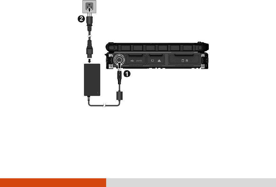
Connecting to AC Power
The computer operates either on the external AC power or internal
battery power. It is suggested that you use AC power when you start up
the computer for the very first time.
CAUTION: Use only the AC adapter included with your computer. Using other AC
adapters may damage the computer.
1. Make sure that the computer is turned off.
2. Plug the DC cord of the AC adapter to the power connector of the
computer ().
3. Plug the female end of the AC power cord to the AC adapter and the
male end to an electrical outlet ().
4. When the AC adapter is connected, power is being supplied from the
electrical outlet to the AC adapter and onto your computer. Now,
you are ready to turn on the computer.

1-4 Getting Started
CAUTION:
When you disconnect the AC adapter, disconnect from the electrical outlet
first and then from the computer. A reverse procedure may damage the AC
adapter or the computer.
When unplugging the connector, always hold the plug head. Never pull on the
cord.
NOTE: When the AC adapter is connected, it also charges the battery pack. For
information on using battery power, see Chapter 3.
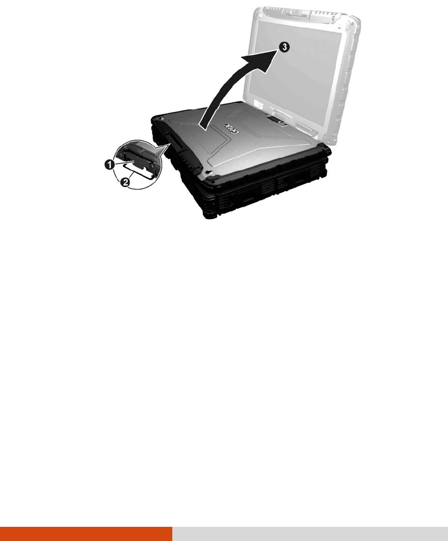
Opening and Closing the Cover
To open the top cover:
1. Pull loose the cover latch () and release the clamp ().
2. Lift up the cover (). You can tilt the cover forward or backward for
optimal viewing clarity.
Getting Started 1-5
To close the top cover:
1. Close the display.
2. Lift the cover latch and engage the clamp on the display. Then, push
in the cover latch to click it into place.
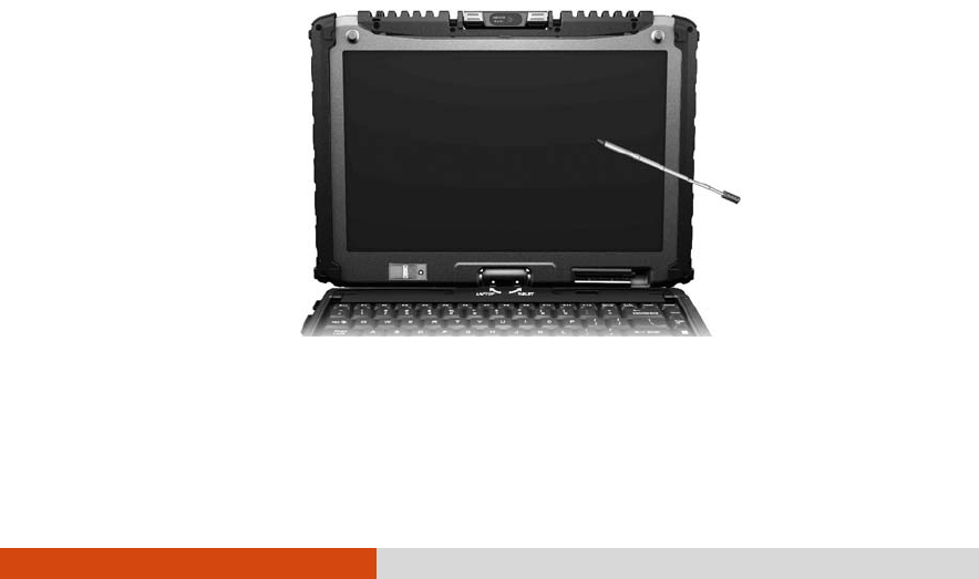
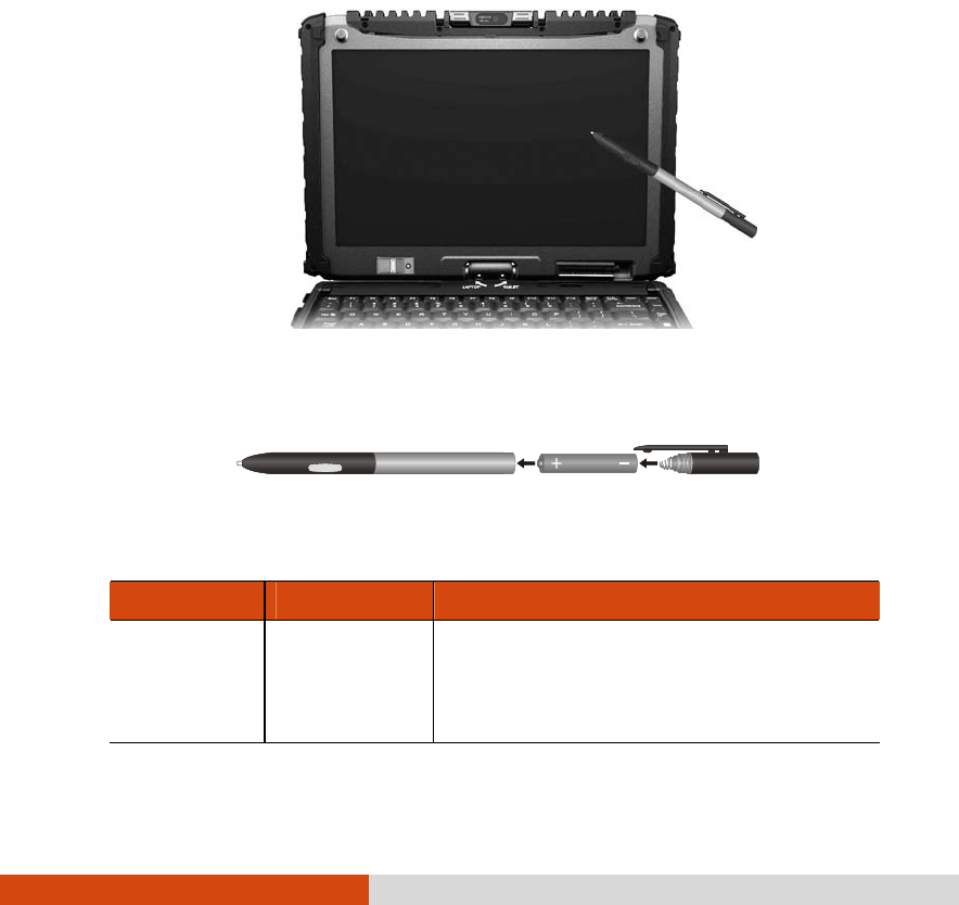
Operating in Tablet Mode
In addition to being used as a regular notebook computer (Laptop
mode), your computer can also be operated in Tablet mode. In Tablet
mode, you operate the computer with a stylus or digitizer pen, or a
fingertip, instead of a keyboard or mouse.
1. Open the top cover so that it is almost perpendicular with the
keyboard of the computer.
2. Turn the display counter-clockwise by 165o.
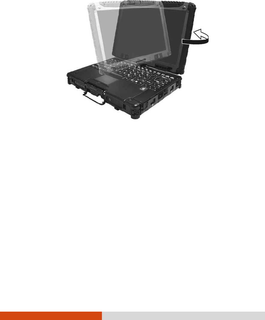
1-6 Getting Started
CAUTION: Do not rotate the display more than 165o, or attempt to rotate the
display clockwise.
3. Close the computer with the display facing up.
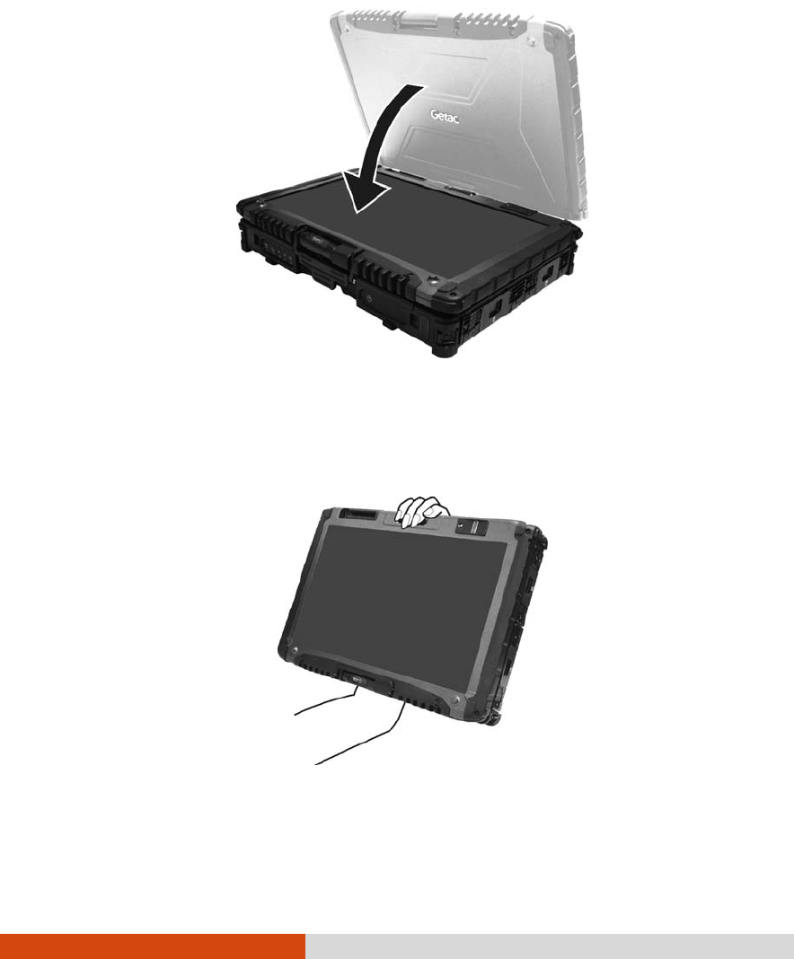
Getting Started 1-7
4. Lift the cover latch and engage the clamp on the display. Then, push
in the cover latch to click it into place.
In Tablet mode, the computer can be operated while holding it as shown.
To return to Laptop mode, perform the steps for changing the computer
into Tablet mode in reverse order.
1-8 Getting Started
Turning On and Off the Computer
Turning On
1. Make sure that the computer is connected to AC power.
2. Press the power button ( ).
3. Each time the computer is turned on, it performs a Power-On Self Test
(POST), and the operating system such as Windows should start.
Turning Off
To turn off the computer power, use the “Shut Down” command of your
operating system.
NOTE: There are other ways you can stop the computer so that you will be back
to where you left off when you next turn on the computer. (See “Stopping the
Computer” in Chapter 2 for information.)
CAUTION: If you have to turn the computer on again immediately after turning it
off, wait for at least five seconds. Turning the computer off and on rapidly can
damage it.
Getting Started 1-9
Taking a Look at the Computer
NOTE:
Depending on the model you purchased, the appearance of your computer
may not be exactly the same as those shown in this manual.
You need to open the protective covers to access the connectors. When not
using a connector, make sure to close the cover completely for water- and
dust-proof integrity. (Engage the locking mechanism if existing.)
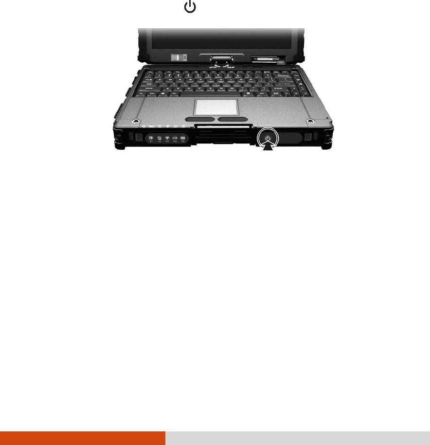
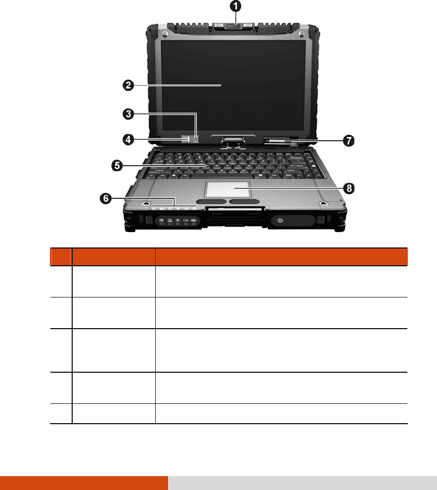
Front Components
Ref Component Description
Hand Strap
Holder The hand strap can be attached to the two holders
for convenient handling of your computer.
Speaker
Sends out sound and voice from your computer.
OSD Control
Button Opens or closes the OSD (On Screen Display) control
panel.
P1 Can be re-defined using the OSD utility. (See “Using
Button Manager” in Chapter 7 for information.)
Sunlight-
readable
Button
Toggles the sunlight-readable mode ON and OFF.
IMPORTANT: To prevent burns to your fingers if using the
computer (especially in Tablet Mode) with
sunlight-readable mode turned on, do wear gloves
when touching the top portion of the LCD display as it
may be hot to the touch.

1-10 Getting Started
Ref Component Description
P2 Can be re-defined using the OSD utility. (See “Using
Button Manager” in Chapter 7 for information.)
RF Button Toggles the wireless LAN /Bluetooth/3G radio
frequency ON and OFF.
P3 Can be re-defined using the OSD utility. (See “Using
Button Manager” in Chapter 7 for information.)
Reset Button
Serves as the Ctrl+Alt+Del keyboard keys.
P4 Can be re-defined using the OSD utility. (See “Using
Button Manager” in Chapter 7 for information.)
Software
Keyboard
Button
Opens or closes the software keyboard on your
screen.
P5 Can be re-defined using the OSD utility. (See “Using
Button Manager” in Chapter 7 for information.)
Top Cover
Latch Locks the top cover.
Power Button
Turns the computer power ON and OFF.
Getting Started 1-11
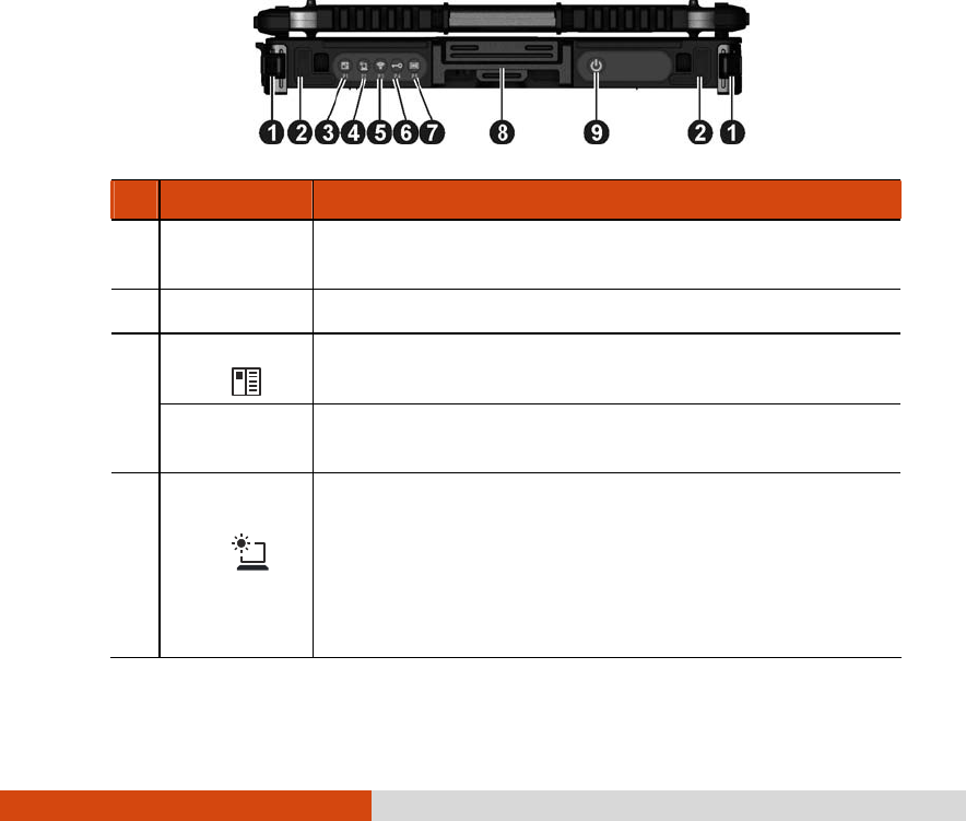
Rear Components
Ref Component Description
Hand Strap Holder The hand strap can be attached to the two holders
for convenient handling of your computer.
Audio Output
Connector Connects a set of headphones, external speakers
with amplifier, or an audio recording device.
Microphone
Connector Connects an external microphone.
USB Port Connects a USB device, such as a flash disk, printer,
digital camera, joystick, and more.
Kensington Lock Locks the computer to a stationary object for
security.
VGA Connector Connects an external display monitor.
NOTE: Depending on your model, this port could be
a serial connector.
Serial Connector Connects a serial mouse or serial communication
device.
1-12 Getting Started
Right-Side Components
Ref Component Description
Battery Pack
Compartment Inside is the battery pack that supplies power to
your computer when external power is not
connected.
Hard Disk Drive
Compartment Inside is the hard disk drive.
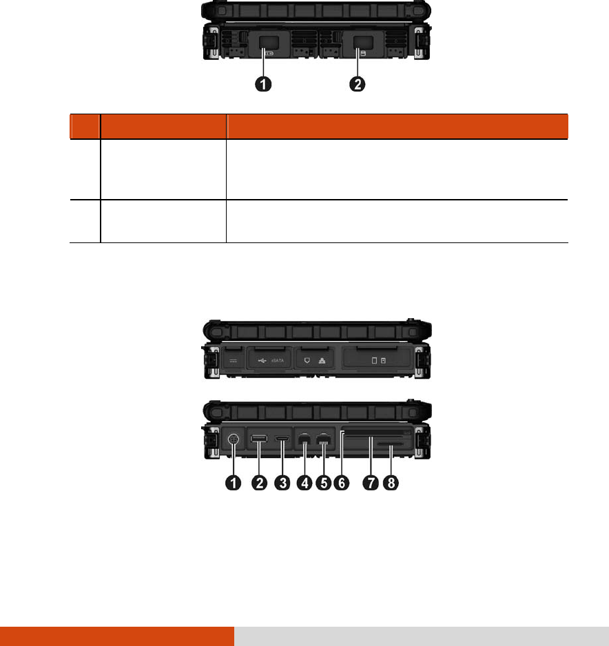
Left-Side Components

Getting Started 1-13
Ref Component Description
Power Connector Connects the AC adapter.
USB Port Connects a USB device, such as a flash disk,
printer, digital camera, joystick, and more.
Connects an eSATA device such as an external
hard drive or optical drive.
eSATA/USB Combo
Port
Can also function as a USB port.
RJ-11 Connector Connects the telephone line.
RJ-45 Connector Connects the LAN cable.
Can be one of the below depending on your model:
ExpressCard Slot Accepts an ExpressCard for additional functions.
PCMCIA Slot Accepts a PC card for additional functions.
Can be one of the below depending on your model:
Smart Card Reader Accepts a smart card for additional security
feature.
PCMCIA Slot Accepts a PC card for additional functions.
SD Card Reader Accepts a SD (Secure Digital) card for removable
storage media.
1-14 Getting Started
Top-open Components
Ref Component Description
Webcam Lens
(option) Allows you to use your computer’s camera
function. The camera lens can be rotated.
LCD Screen Displays the output of the computer.
May include the optional touchscreen feature.
Light Sensor Detects the surrounding lighting condition for
automatic adjustment of the LCD brightness and
optional keyboard backlight.
Fingerprint
Scanner (option) Uses fingerprint verification to protect your
computer against unauthorized access.
Keyboard Serves as the data input device.
Getting Started 1-15
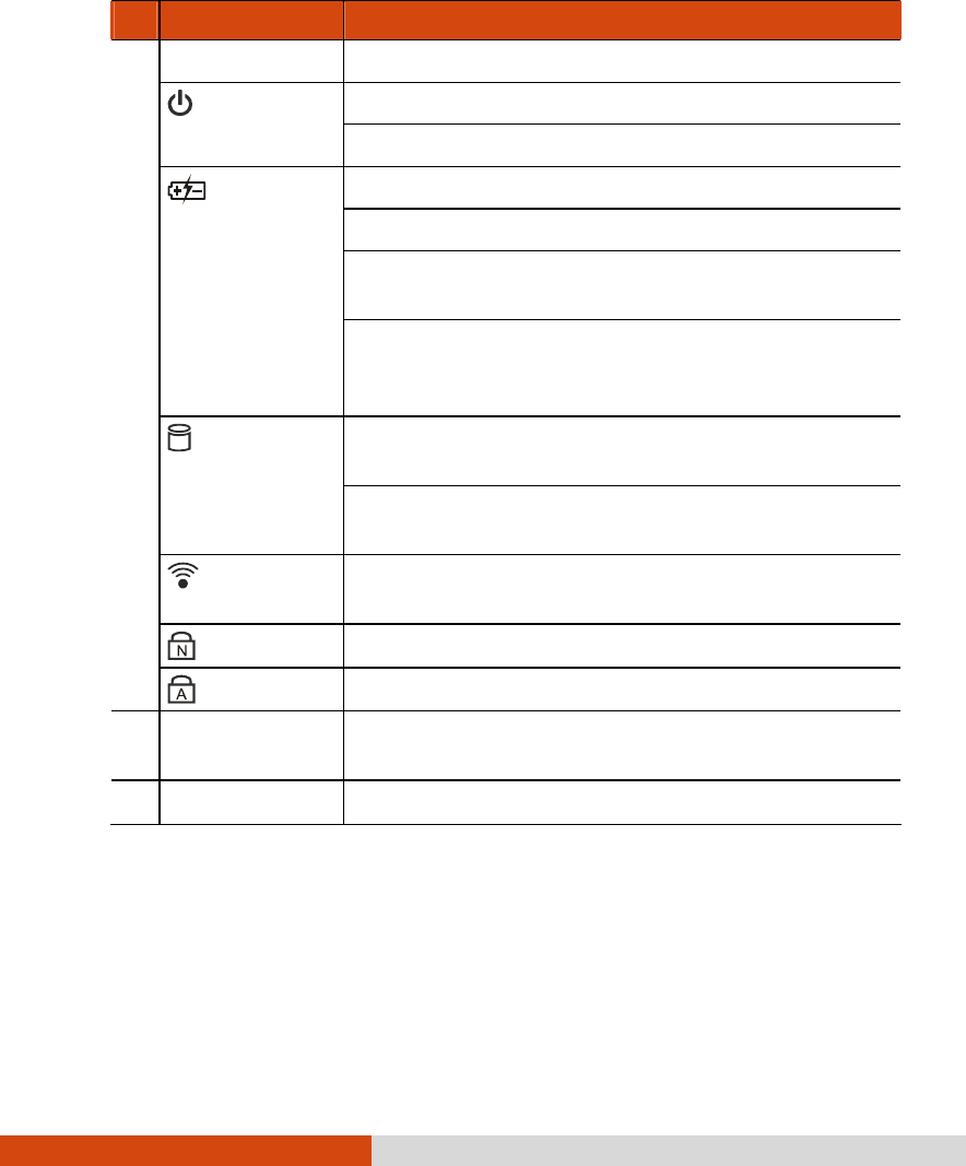
Ref Component Description
Indicators Show the current status of the computer’s devices.
Lights green when the computer is turned on.
Power
Lights yellow when the computer is in Sleep mode.
Lights green when the battery is fully charged.
Lights yellow when the battery is being charged.
Blinks yellow when the battery’s capacity is below
10%.
Battery
Charge
Blinks green and yellow by turns to indicate
charging is suspended because the battery’s
temperature is either too high or too low.
Lights green when the computer is accessing the
hard disk drive.
Hard Disk
Drive In-Use
Blinks red when the optional hard disk drive heater
is on for low temperature operation.
RF Lights when the wireless LAN/Bluetooth/3G radio
frequency is on.
Num Lock Lights when Num Lock is on.
Caps Lock Lights when Caps Lock is on.
Stylus/Digitizer
Pen (option) Serves as the input device by tapping on the
screen to make selections and enter information.
Touchpad Serves as the pointing device.
1-16 Getting Started
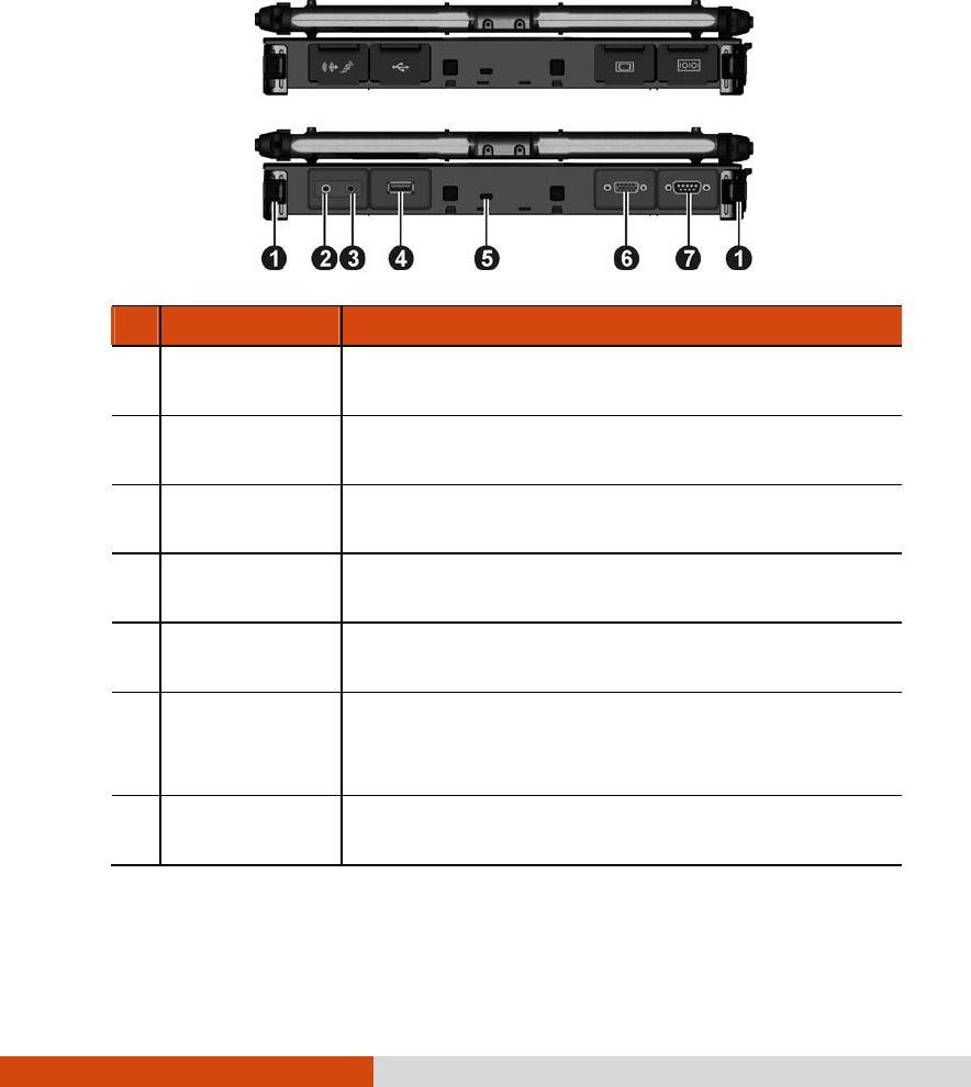
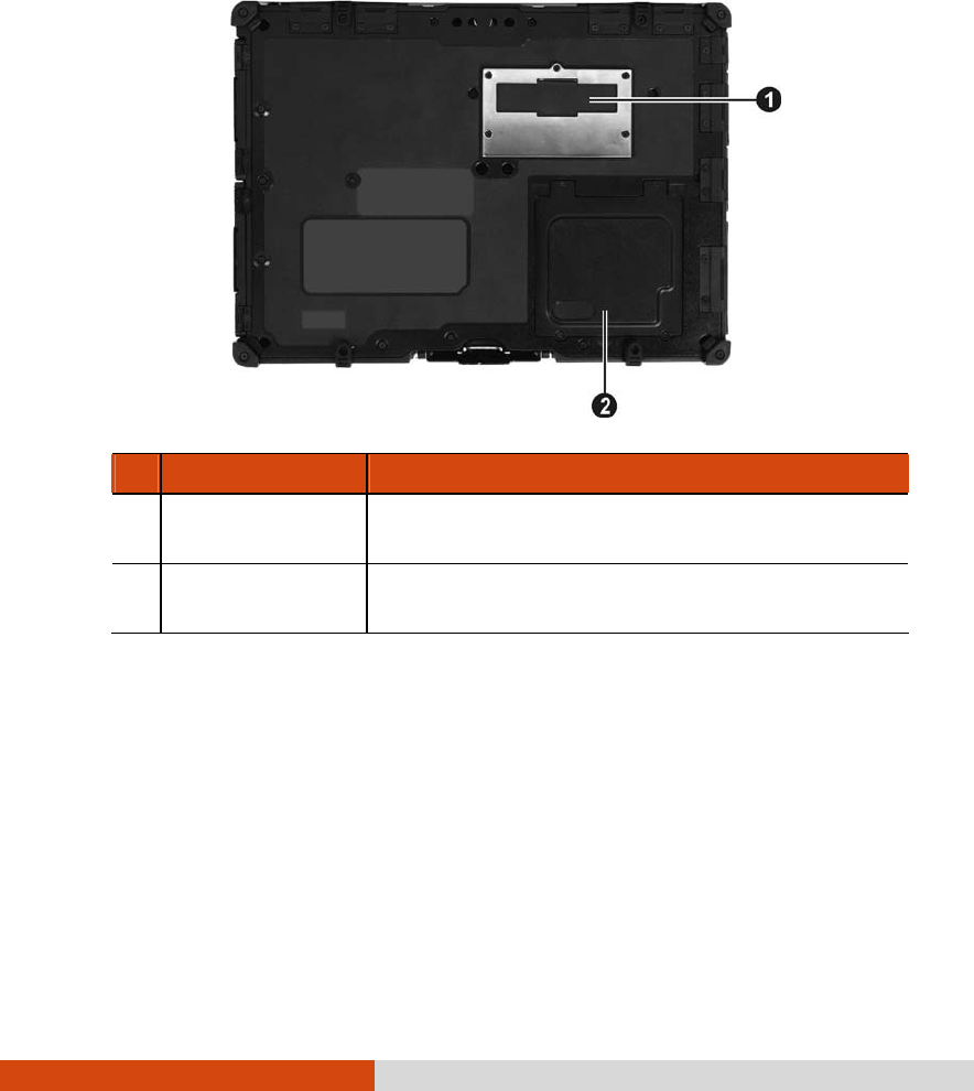
Bottom Components
Ref Component Description
Expansion Bus
Connector Inside is the expansion bus connector for using
the Port Replicator option.
Memory Slots Inside are the memory slots for expanding the
memory size of your computer.

Getting Started 1-17
Using the Accessories
Using the Tether (Optional)
A tether is provided for attaching the stylus to your computer.
1. Insert one of the tether’s loop ends through the hole of the stylus (as
indicated by below). Then, insert the other end through the first loop
(as indicated by below) and pull it tight.
2. Insert the other loop end to the tether hole on the computer (as
indicated by below). Then, insert the stylus end through the loop (as
indicated by below) and pull it tight.
1-18 Getting Started
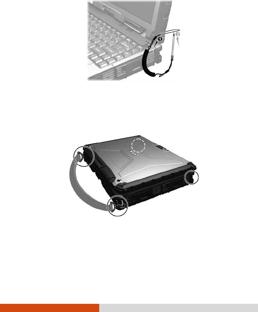
Attaching the Hand Strap
The hand strap can be attached to any side of your computer. To use the
hand strap, secure the snap hooks to the holders on your computer.
CAUTION:
The strap has been designed to carry only the weight of the computer.
Therefore, be sure that the strap does not carry a weight that exceeds the
weight of the computer. The strap may accidentally come loose from the
computer.
Do not use a strap that is damaged or about to tear.

Getting Started 1-19

Operating Your Computer 2-1
Chapter 2
Operating Your Computer
This chapter provides information about the use of the computer.
If you are new to computers, reading this chapter will help you learn the
operating basics. If you are already a computer user, you may choose to
read only the parts containing information unique to your computer.
CAUTION: The computer can get uncomfortably warm when you use it in high
temperatures. As a safety precaution in such a circumstance, do not place the
computer on your lap or touch it with your bare hands for extended periods of
time. Prolonged body contact can cause discomfort and potentially a burn.

2-2 Operating Your Computer
Starting and Stopping the Computer
There are a number of ways to start and stop the computer.
Starting the Computer
You always start the computer using the power button.
A computer starts up with an operating system (OS) existing on the
storage device such as the hard disk. The computer will automatically
load the OS after you turn it on. This process is called booting.
NOTE: An operating system is the platform for all your software application
programs to run on. Your computer uses the Microsoft Windows operating
system.
Stopping the Computer
When you finish a working session, you can stop the computer by turning
off the power or leaving the computer in Standby/Sleep or Hibernation
mode:
To stop in this
mode... Do this... To start up or
resume again
Off Follow the shutdown procedure of
your operating system. This can
prevent loss of unsaved data or
damage to your software programs.
If the system is locked up because of
hardware or software problems, press
the power button to turn off the
computer.
Press the power
button.
Standby/Slee
p Depending on your settings in
Windows, you can place the Press any key.

Operating Your Computer 2-3
To stop in this
mode... Do this... To start up or
resume again
computer in Standby/Sleep mode
by:
Closing the display cover
Pressing the Fn+F12 hot key
Pressing the power button
Hibernation Depending on your settings in
Windows, you can place the
computer in Hibernation mode by:
Closing the display cover
Pressing the Fn+F12 hot key
Pressing the power button
Press the power
button.
If you choose to stop in Standby/Sleep or Hibernation mode, you can
return to where you left off the next time you start up the computer. (See
“Power Management” in Chapter 3 for more information.)

2-4 Operating Your Computer
Using the Internal Keyboard
Your keyboard has all the standard functions of a full-sized computer
keyboard plus an Fn key added for specific functions.
The standard functions of the keyboard can be further divided into four
major categories:
Typewriter keys
Cursor-control keys
Numeric keys
Function keys
Typewriter Keys
Typewriter keys are similar to the keys on a typewriter. Several keys are
added such as the Ctrl, Alt, Esc, and lock keys for special purposes. When
the lock keys (Caps Lock and Num Lk) are pressed, their corresponding
indicators light up.
The Control (Ctrl) / Alternate (Alt) key is normally used in combination with
other keys for program-specific functions. The Escape (Esc) key is usually
used for stopping a process. Examples are exiting a program and
canceling a command. The function depends on the program you are
using.
Cursor-Control Keys
Cursor-control keys are generally used for moving and editing purposes.
NOTE: The word “cursor” refers to the indicator on the screen that lets you know
exactly where on your screen anything you type will appear. It can take the form of
a vertical or horizontal line, a block, or one of many other shapes.
Operating Your Computer 2-5
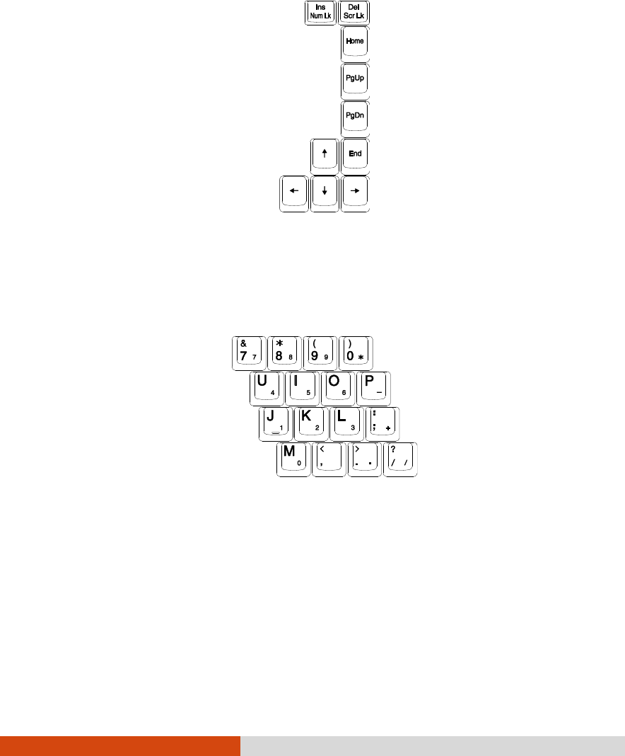
Numeric Keypad
A 15-key numeric keypad is embedded in the typewriter keys as shown
next:
Numeric keys facilitate entering of numbers and calculations. When Num
Lock is on, the numeric keys are activated; meaning you can use these
keys to enter numerals.
NOTE:
When the numeric keypad is activated and you need to type the English letter
in the keypad area, you can turn Num Lock off or you can press Fn and then
the letter without turning Num Lock off.
Some software may not be able to use the numeric keypad on the computer.
If so, use the numeric keypad on an external keyboard instead.
2-6 Operating Your Computer
Function Keys
On the top row of the keys are the function keys: F1 to F12. Function keys
are multi-purpose keys that perform functions defined by individual
programs.
Fn Key
The Fn key, at the lower left corner of the keyboard, is used with another
key to perform the alternative function of a key. The letter “Fn” and the
alternative functions are identified by the color of blue on the keytop. To
perform a desired function, first press and hold Fn, then press the other key.
Hot Keys
Hot keys refer to a combination of keys that can be pressed any time to
activate special functions of the computer. Most hot keys operate in a
cyclic way. Each time a hot key combination is pressed, it shifts the
corresponding function to the other or next choice.
You can easily identify the hot keys with the icons imprinted on the keytop.
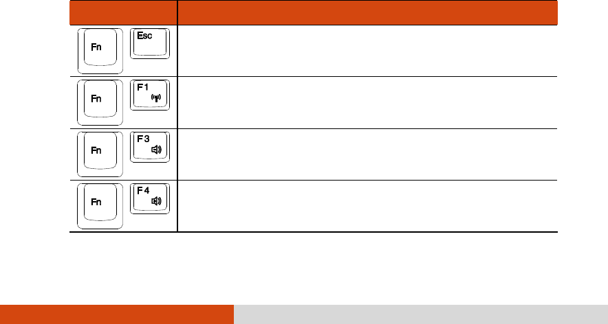
The hot keys are described next.
Key Description
Switches the keyboard backlight on and off
(optional).
Switches the wireless radio on and off.
Decreases the sound volume.
Increases the sound volume.
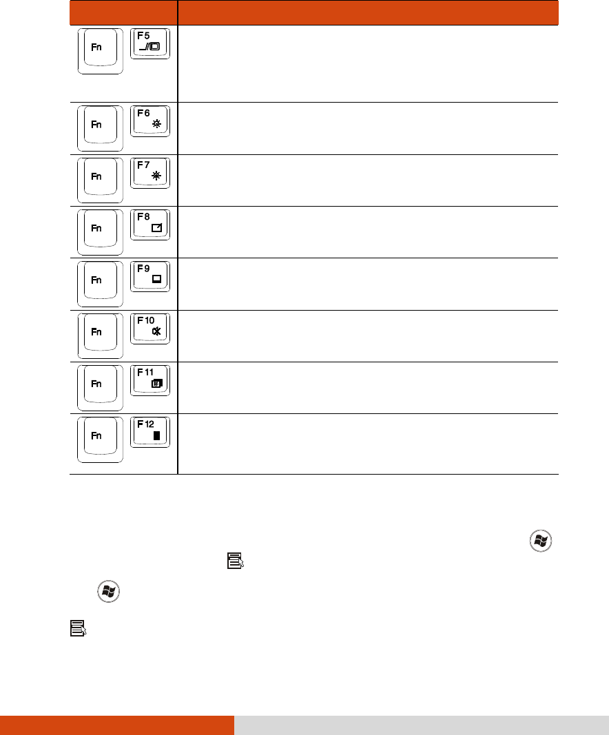
Operating Your Computer 2-7
Key Description
Switches the display output when external devices
are connected.
NOTE: This function only applies to Plug & Play display
devices.
Decreases the LCD brightness (20 levels).
Increases the LCD brightness (20 levels).
Switches the touchscreen on and off (option).
Switches the touchpad on and off.
Switches the system sound output off (mute) and on.
Switches LCD backlight on and off.
Serves as the sleep button that you can define with
Windows’ Power Options. (See the “Power
Management” in Chapter 3.)
Windows Keys
The keyboard has two keys that perform Windows-specific functions:
Windows Logo key and Application key.
The Windows Logo key opens the Start menu and performs
software-specific functions when used in combination with other keys. The
Application key usually has the same effect as a right mouse click. (See
your Windows manual for more information.)
2-8 Operating Your Computer
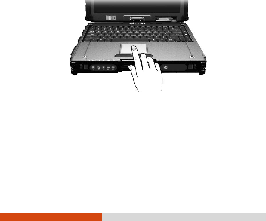
Using the Touchpad
CAUTION: Do not use a sharp object such as a pen on the touchpad. Doing so
may damage the touchpad surface.
NOTE: For optimal performance of the touchpad, keep your fingers and the pads
clean and dry. When tapping on the pad, tap lightly. Do not use excessive force.
The touchpad is a pointing device that allows you to communicate with
the computer by controlling the location of the pointer on the screen and
making selection with the buttons.
The touchpad consists of a rectangular pad (work surface) and a left and
right buttons. To use the touchpad, place your forefinger or thumb on the
pad. The rectangular pad acts like a miniature duplicate of your display.
As you slide your fingertip across the pad, the pointer (also called cursor)
on the screen moves accordingly. When your finger reaches the edge of
the pad, simply relocate yourself by lifting the finger and placing it on the
other side of the pad.
Here are some common terms that you should know when using the
touchpad:

Operating Your Computer 2-9
Term Action
Point Move your finger on the pad until the cursor points to the
selection on the screen.
Click Press and release the left button.
–or–
Tap gently anywhere on the pad.
Double-click
Press and release the left button twice in quick
succession.
–or–
Tap twice on the pad rapidly.
Drag and
drop Press and hold the left button, then move your finger until
you reach your destination (drag). Finally, release the
button (drop) when you finish dragging your selection to
the destination. The object will drop into the new
location.
–or–
Gently tap twice on the pad and on the second tap,
keep your finger in contact with the pad. Then, move
your finger across the pad to drag the selected object to
your destination. When you lift your finger from the pad,
the selected object will drop into place.
Scroll To scroll is to move up and down or left and right in the
working area on the screen.
To move vertically, place your finger on the right or left
edge of the pad and slide your finger up and down
along the edge. To move horizontally, place your finger
on the top or bottom edge of the pad and slide your
finger left and right.
This function works only after you install the touchpad
driver supplied with the computer and it may not work for
all applications.

2-10 Operating Your Computer
TABLE NOTE: If you swap the left and right buttons, “tapping” on the
touchpad as an alternative method of pressing the left button will no
longer be valid.
Configuring the Touchpad
You may want to configure the touchpad to suit your needs. For example,
if you are a left-handed user, you can swap the two buttons so that you
can use the right button as the left button and vice versa. You can also
change the size of the on-screen pointer, the speed of the pointer, and so
on.
To configure the touchpad, go to Control Panel Mouse Properties.
Operating Your Computer 2-11
Navigating on the Screen
The screen of your computer is touch-sensitive. You can control the
location of the cursor/pointer on the screen using your finger or the
included stylus or digitizer pen to communicate with the computer.
CAUTION: Do not use sharp objects on the LCD display. Doing so may damage
the display surface. Use your finger or the included stylus or digitizer pen.
NOTE: When there is a noticeable discrepancy in the placement of the stylus on
the screen and the indicated position of the onscreen pointer, calibrate the
touchscreen using the calibration utility called IdeaCom Calibration on Windows
XP/Vista or CalTouch on Windows 7.
Using the Touchscreen
If your computer is equipped with the touchscreen feature, you can use
your finger or the included stylus to navigate and select objects on the
screen.
2-12 Operating Your Computer
Here are some common terms that you should know when using the
touchscreen:
Term Action
Click/Point Tap gently on the touchscreen.
Double-click Tap twice on the touchscreen rapidly.
Drag and
drop Tap lightly on the touchscreen and move your finger
until you reach your destination (drag). Finally, release
your finger (drop) when you finish dragging your
selection to the destination. The object will drop into
the new location.
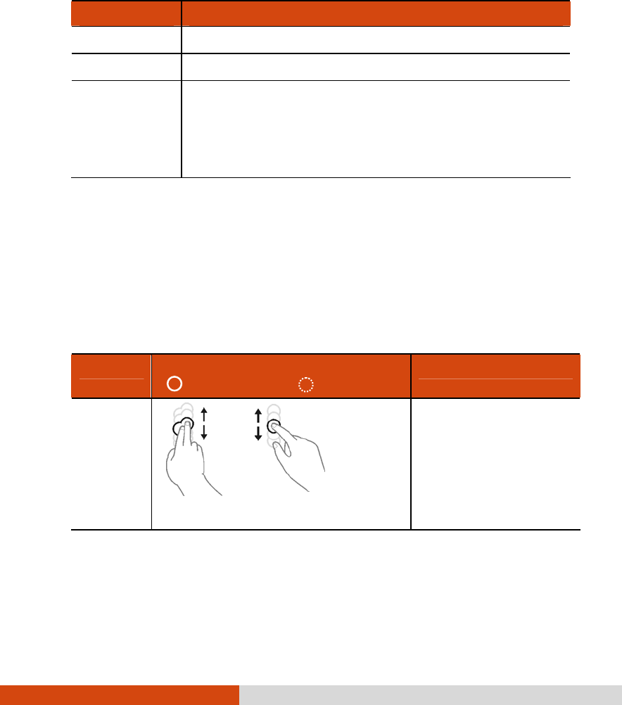
Using Multi-touch Gestures (Windows 7 Only)
If your computer model comes with multi-touch-capable screen and
Windows 7, you can interact with your computer by placing two fingers on
the screen. The movement of the fingers across the screen creates
“gestures,” which send commands to the computer.
Here are the multi-touch gestures that you can use:
Gestures Actions
( = finger down; = finger up) Descriptions
Pan
(Scroll)
or
Drag 1 or 2 fingers up or down.
Use panning to see
another part of a
page that has scroll
bars.
Operating Your Computer 2-13
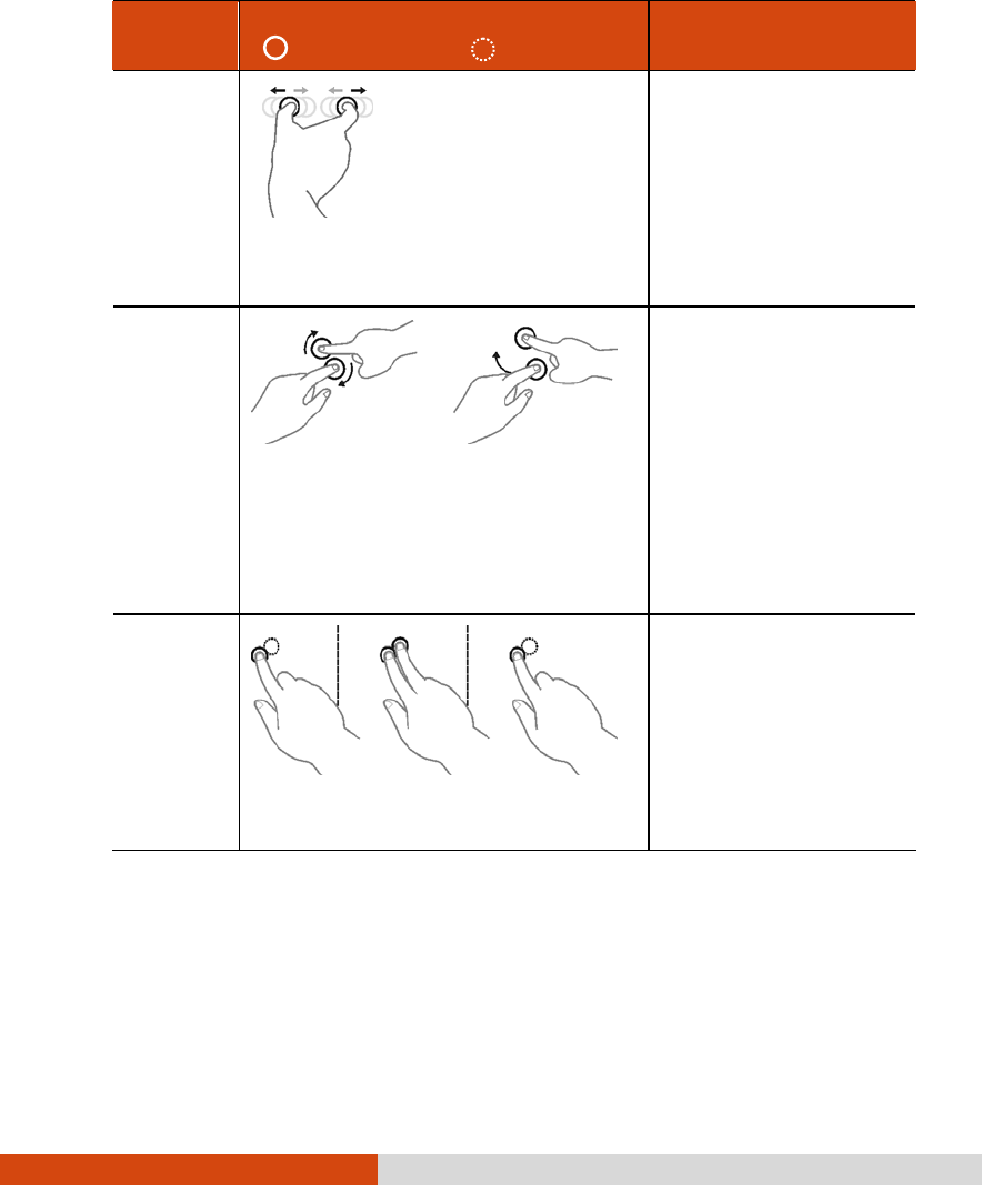
Gestures Actions
( = finger down; = finger up) Descriptions
Zoom
(Pinch)
Move two fingers apart/toward
each other.
Use zooming to make
an item (a photo for
example) on the
screen larger or
smaller. The gesture
works in applications
that support mouse
wheel zooming.
Rotate
or
Move two fingers in opposing
directions.
-or-
Use one finger to pivot around
another.
Use rotating to move
a picture or other
item on the screen in
a circular direction
(clockwise or counter-
clockwise). The
gesture works in
applications that
support the specific
gesture.
Press
and Tap
Press on target and tap using a
second finger.
Use press and tap to
access the shortcut
menu.
2-14 Operating Your Computer
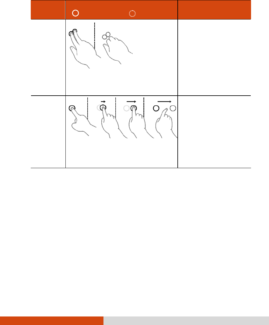
Gestures Actions
( = finger down; = finger up) Descriptions
Two-
finger
Tap
Tap two fingers at the same time
(where the target is in the midpoint
between the fingers).
The function is
defined by
applications that
support the specific
gesture.
Flicks
Make quick drag gestures in the
desired direction.
Flick left or right to
navigate back and
forward in a browser
and other
applications. The
gesture works in most
applications that
support back and
forward.
Operating Your Computer 2-15
Using the Dual Mode Display (Optional)
Dual mode display incorporates both touchscreen and digitizer functions.
The display is set to Touchscreen mode by default. Touchscreen mode
provides all the functionalities that an ordinary touchscreen has. When the
computer receives signals from the active digitizer pen, the display
automatically switches to Digitizer mode.
When using the digitizer pen, be sure to install the included size “AAAA”
battery.
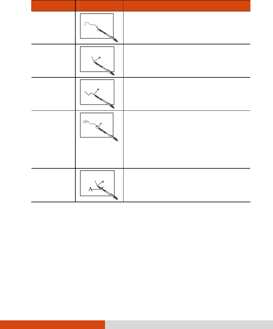
Here are some common terms that you should know when using the
active digitizer feature:
Term Action
Wake up The digitizer pen automatically enters
Sleep mode after 30 seconds of
inactivity. To start using the pen, tap the
tip of the pen to activate it.
2-16 Operating Your Computer
Term Action
Move
Move the cursor pointed by the digitizer
pen.
Click/Point
Tap gently on the display.
Double-clic
k
Tap twice on the display rapidly.
Drag and
drop
Tap lightly on the display and move
your digitizer pen until you reach your
destination (drag). Finally, release your
digitizer pen (drop) when you finish
dragging your selection to the
destination. The object will drop into the
new location.
Right-click
Press and hold down the digitizer pen
button (A), then tap gently the object.
CAUTION:
When the LCD display is used alone or with an external display
simultaneously, the digitizer function cannot be used when the area of either
display is set larger than the default setting of the display resolution.
Even when only an external display is in use, the cursor will move on the
external display if you touch the surface of the LCD display with the pen or
bring the pen close to the surface of the LCD display when the digitizer driver
is active. Therefore, do not touch the LCD display when only an external
display is in use.
The active digitizer feature cannot be used in the BIOS Setup program or
when using the full screen in DOS mode.

Operating Your Computer 2-17
NOTE:
You can move the cursor by bringing the digitizer pen close to the screen,
without actually touching the screen’s surface.
Do not move the digitizer pen too quickly. If the pen moves too quickly, the
cursor may be unable to follow its movement.
If you cannot click on the edge of the screen, hold the digitizer pen
perpendicular to the display and try clicking again.
2-18 Operating Your Computer
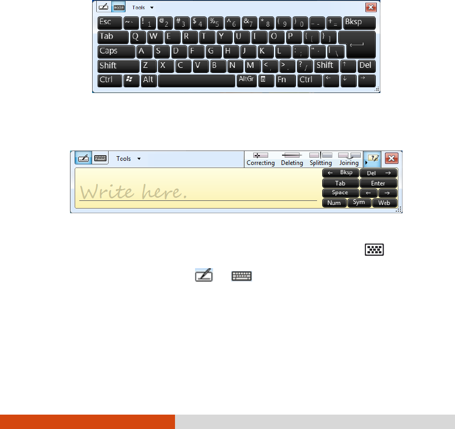
Using the Input Panel
Use the Input Panel to enter text and perform various keyboard functions.
There are two types of Input Panels for you to use in Windows 7:
Touch Keyboard allows you to enter text by tapping the keys with your
stylus, like pressing the keys on a standard keyboard.
Writing Pad allows you to write on the writing pad, like writing on a piece
of paper. Your handwriting will be converted into typed text.
To open the Input Panel, tap the Input Panel tab, which appears by
default on the left edge of the screen. (You can also press the button
on the front of the computer to open or close the Input Panel.) To switch
between the two types, tap or at the upper left corner of the
Input Panel.
NOTE: For more information on using the Input Panel, see Windows’ online help.
Operating Your Computer 2-19
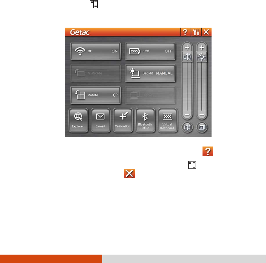
Using OSD Control Panel
The OSD Control Panel allows you to easily activate or operate certain
functions on your computer.
To use the OSD Control Panel:
1. Press the button on the front of your computer.
2. The following screen appears, providing several control buttons.
For detailed descriptions of the Control Panel, click the button.
3. To close the Control Panel, either press the button on your
computer again or click the button .
2-20 Operating Your Computer
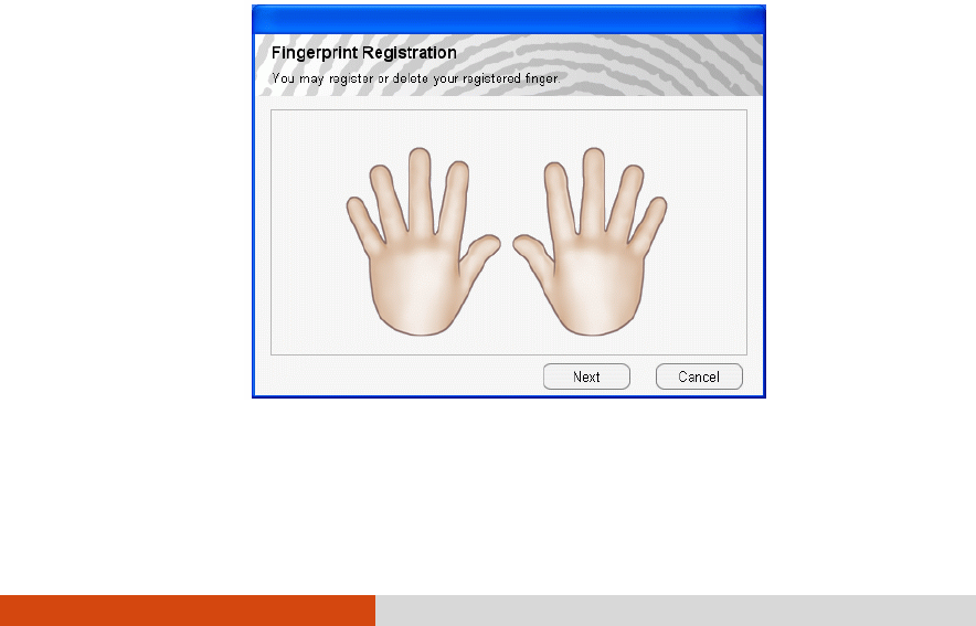
Using the Fingerprint Scanner
(Optional)
The fingerprint scanner provides a strong authentication mechanism
based on fingerprint recognition. You can log on to your computer or sign
in to a web site with your fingerprint instead of a password. You can also
encrypt files and folders with your fingerprint.
NOTE: You can register a fingerprint only after creating a password for the
Windows user account.
CAUTION: For the fingerprint file/folder encryption feature, the maximum
file/folder size allowed is 2GB.
To register your fingerprint, click Start All Programs Fingerprint Software
Fingerprint Registration. Click the finger you want to register and follow the
onscreen instructions to complete.

Operating Your Computer 2-21
You can then use the Fingerprint Software to set up how the fingerprint
authentication works.
For detailed information, click Start All Programs Fingerprint Software
Help.

2-22 Operating Your Computer
Using the Video Features
The video subsystem of your computer features:
12.1-inch wide TFT (Thin-Film Transistor) color LCD display with 1200×800
WXGA resolution
Simultaneous display on LCD and external monitor
Multi-display capability
Built-in light sensor to automatically adjust the LCD brightness and
optional keyboard backlight
Power Management
Sunlight-readable LCD display
NOTE: The computer enters the Standby/Sleep or Hibernation mode when the
LCD is closed. If you want to use the computer with the LCD closed, set according
in Windows Control Panel so the computer does not enter the Standby/Sleep or
Hibernation mode when the LCD is closed.
Configuring the Display Modes
NOTE: When using an external CRT monitor, the resolution depends on the CRT
monitor’s supported resolution.
Your computer has been set to a default resolution and number of colors
before shipment. You can view and change display settings through your
operating system. See your operating system documentation or online
help for specific information.
For displaying in higher resolutions, you can connect an external monitor
that supports higher resolutions. (See “Connecting an External Monitor” in
Chapter 4 for more information.)
Operating Your Computer 2-23
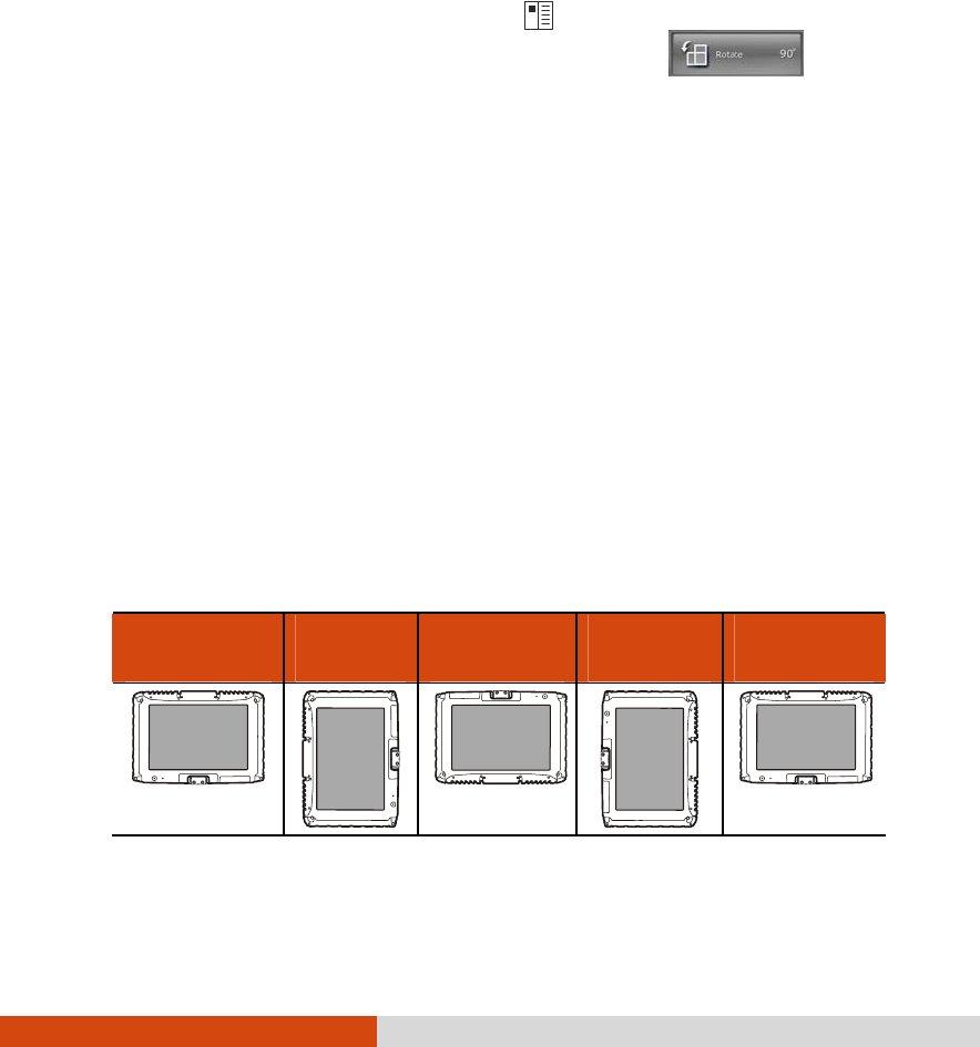
Using Landscape or Portrait View
After Windows is started up, you can rotate the display and perform the
touchscreen and active digitizer operations in the rotated mode.
To rotate the display, press the button located on the front of your
computer to open the OSD control panel and click . Each
time this Rotate button is clicked, the screen display rotates
counter-clockwise by 90O.
NOTE:
If the screen display resolution has been set to 800×600 pixels, you can rotate
the display to Primary Landscape and Secondary Landscape only.
While the display is rotated:
– Do not set the display resolution larger than the resolution of the LCD
display.
– If you exit Windows, the next time Windows is started up, the operation
of the touchpad will not match the display angle for a few seconds.
– The computer’s performance will decrease slightly.
– If a video is played, the picture may not be displayed properly or the
sound may be broken up. This problem can be corrected by rotating
the display to Primary Landscape.
– The touchpad’s scroll function does not work.
The display cannot be rotated when DOS mode is set to “Full Screen.”
For a Model without 3G Module
Primary
Landscape Primary
Portrait Secondary
Landscape Secondary
Portrait Primary
Landscape
Display Display Display
Display Display
2-24 Operating Your Computer
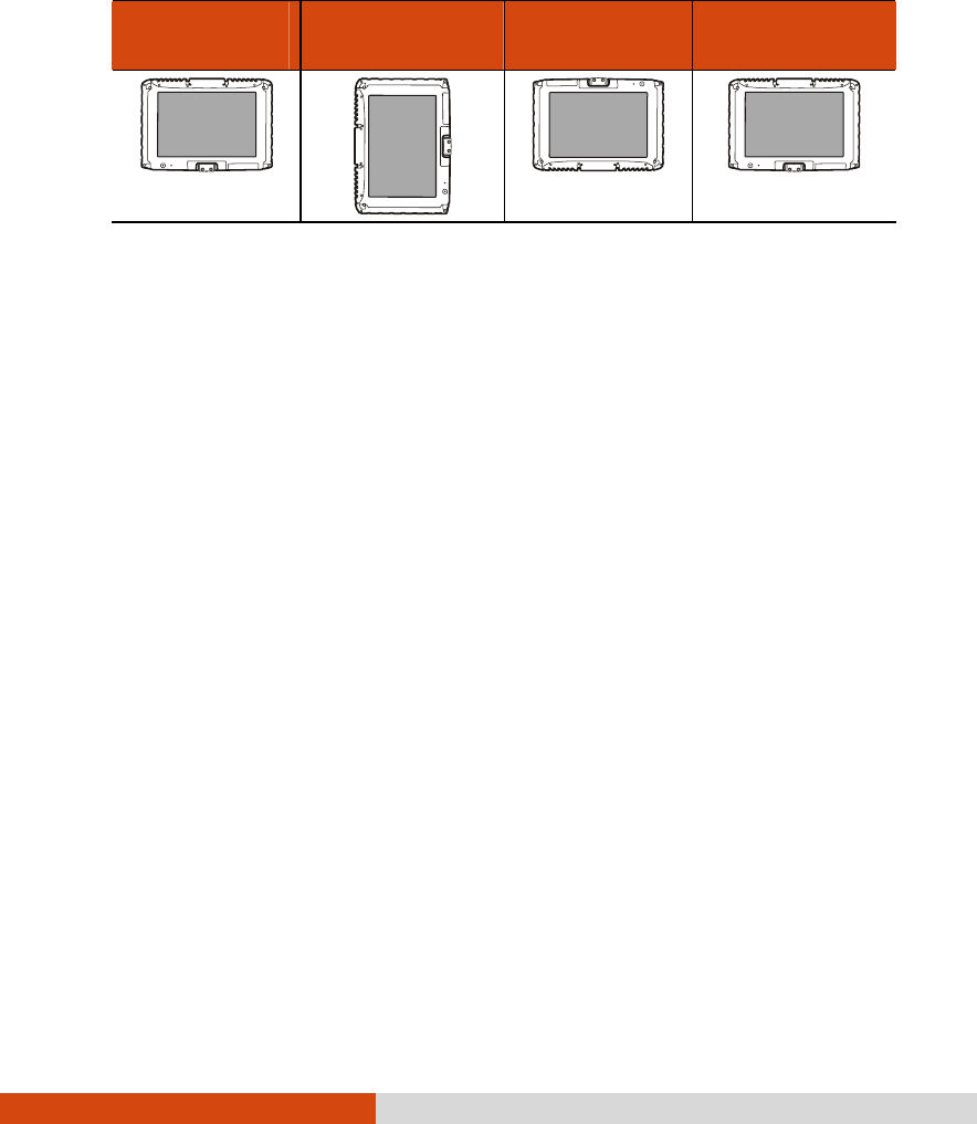
For a Model with 3G Module
Primary
Landscape Primary Portrait Secondary
Landscape Primary
Landscape
Display Display
Display
Display
Operating Your Computer 2-25
Using the Audio Features
NOTE: If you experience interference while recording, try lowering the
microphone recording volume.
The audio subsystem of your computer features:
Built-in sound system for recording and playing sound on your
computer
Azalia interface (high density audio codec)
Built-in Speaker
External audio connectors
Ways of playing and recording sound vary with the operating system
used. See your operating system documentation or online help for specific
information.
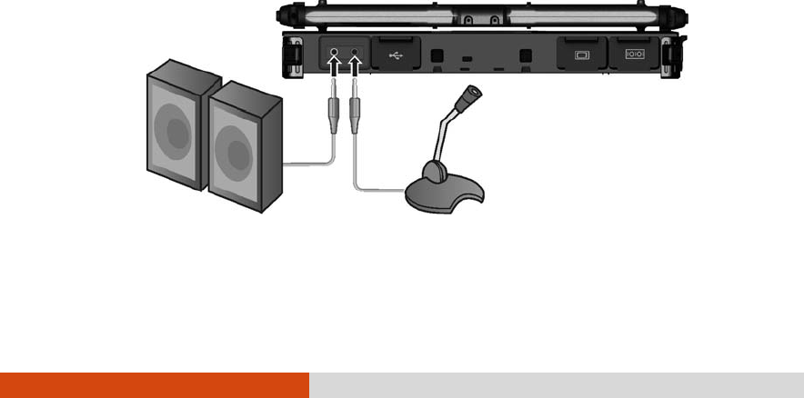
Connecting Audio Devices
For higher audio quality, you can send or receive sound through external
audio devices.
NOTE: After connecting an external audio device, make sure that you specify the
use of the correct audio device in Windows.

2-26 Operating Your Computer
Audio Output Connector ( ) can be connected to speakers,
headphones, or earphone set.
Microphone Connector ( ) can be connected to an external
microphone for recording voice or sound.
NOTE: When using the external speakers/headphones or microphone, you
cannot use the internal one.
Operating Your Computer 2-27
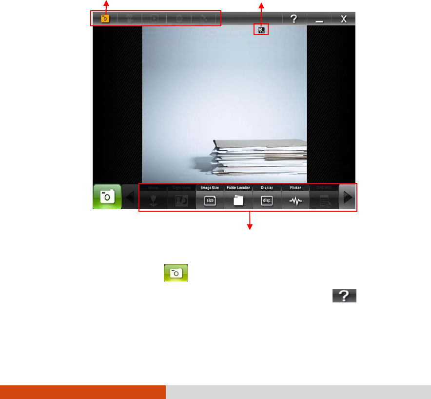
Using G-Camera Lite
G-Camera Lite allows you to take pictures with the Webcam, if supplied with
your computer.
To start G-Camera Lite, click Start All Programs G-Camera Lite G-Camera
Lite. The camera control panel appears.
Click the Shutter button or press Enter to take photos.
For detailed descriptions of G-Camera Lite, click the button .
Mode Current settings
Setting buttons for
different modes
2-28 Operating Your Computer
Using the Network Features
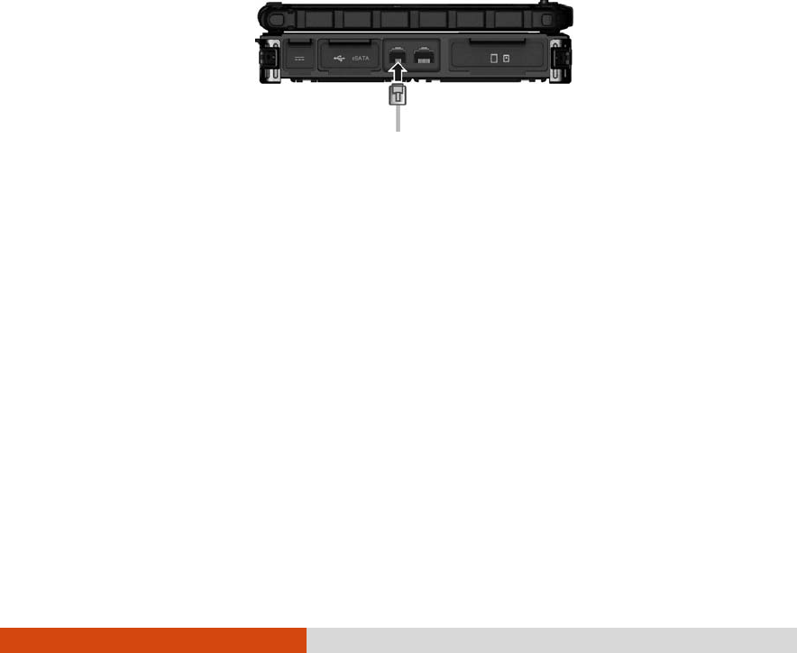
Using the Modem
The internal 56 K fax/data modem allows you to use the telephone line to
communicate with others by fax, email, or connect to an online service or
bulletin board.
To connect the telephone line to the modem, connect one end of the
modem cable to the RJ-11 connector on the computer and the other
end to the phone line.
NOTE:
When using the communication software, you may have to disable power
management.
Set parameters such as modem speed (baud rate) and line type (pulse dialing
or tone dialing).
Do not enter the Standby/Sleep mode when using the communication
software.
Operating Your Computer 2-29
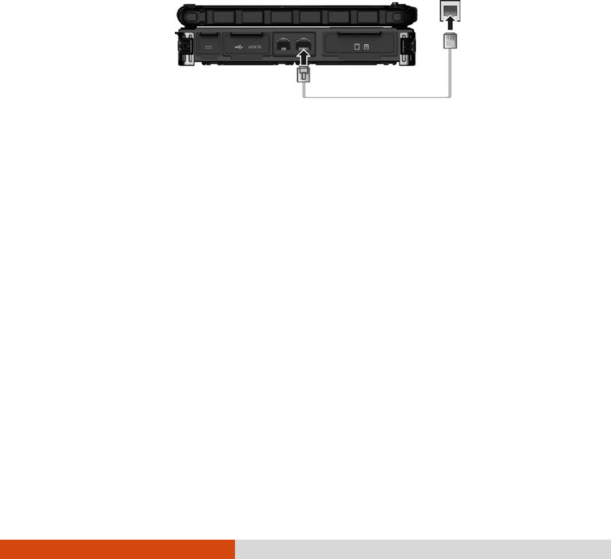
Using the LAN
The internal 10/100/1000Base-T LAN (Local Area Network) module allows
you to connect your computer to a network. It supports data transfer rate
up to 1000 Mbps.
To connect the network cable to the LAN module, connect one end of
the LAN cable to the RJ-45 connector on the computer and the other end
to the network hub.
Using the Wireless LAN
Depending on your model, an internal mini PCI-E wireless LAN (WLAN)
card may have been pre-installed by your computer manufacturer at the
factory. This card allows you to access corporate networks or the Internet
in a wireless environment.
The WLAN features include:
Peer-to-Peer (Ad-Hoc) and Access Point (Infrastructure) modes
support
WEP (Wired Equivalent Privacy) 64/128-bit data encryption
IEEE 802.11a/g/n standard compliance

2-30 Operating Your Computer
Technology 802.11a 802.11g 802.11n
Stated Maximum
Throughput (Mbps) 54 54 100 Mbps or more
Data Rates (Mbps) 54, 48, 36, 24, 18,
12, 9, 6 54, 36, 18, 9 100 ~ 210
Band (GHz) 5.15 ~ 5.35 2.4 2.4 / 5
Modulation
Technology OFDM (Orthogonal
Frequency Division
Multiplexing)
OFDM
(Orthogonal
Frequency
Division
Multiplexing)
Spatial
multiplexing, uses
MIMO (multiple-
input multiple-
output)
To take advantage of the WLAN feature, make sure that the WLAN driver
is installed correctly. If your WLAN card was provided by your dealer
instead of the computer manufacturer, contact your dealer for the
correct driver to use.
Turning On/Off the WLAN Radio
NOTE: The FAA (Federal Aviation Agency) has deemed it unsafe to operate
wireless devices in aircraft as this may interfere with flight safety. Remember to
turn off wireless LAN when using your computer in the airplane.
1. Press Fn+F1 to turn on or off the wireless radio. The indicator lights up
to indicate the wireless radio is on.
2. Windows Mobility Center has wireless network turned on by default.
The Wireless Network icon on the taskbar should appear without a
red X. (In case you have previously turned it off in Windows Mobility
Center, be sure to turn it on when using the function the next time.)
Operating Your Computer 2-31
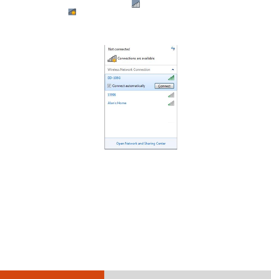
Connecting to a Wireless Network
To connect to a wireless network:
1. Make sure that the WLAN radio is on (as described in the previous
section).
2. Tap the Wireless Network icon on the taskbar. (An orange light in
the icon indicates connections are available.)
3. In the list of available wireless networks, tap a network, and then tap
Connect.
4. Some networks require a network security key or passphrase. To
connect to one of those networks, ask your network administrator or
Internet service provider (ISP) for the security key or passphrase.
For more information on setting a wireless network connection, refer to
Windows online help.
NOTE: You can use Intel® PROSet Wireless to take full advantage of the WiFi
capabilities of your computer. See the Help of the utility for instructions.
2-32 Operating Your Computer
Using the Bluetooth Feature
Your computer incorporates the Bluetooth capability for short-range
(about 10 meters) wireless communications between devices without
requiring a cable connection.
With Bluetooth, data can be transmitted through walls, pockets and
briefcases as long as two devices are within range.
Turning On/Off the Bluetooth Radio
1. Press Fn+F1 to turn on or off the wireless radio. The indicator lights up
to indicate the wireless radio is on.
2. The Bluetooth function is enabled by default, as indicated by the
Bluetooth icon on the Windows taskbar. (In case you have
previously disabled the function in the Bluetooth utility, be sure to
enable it when using the function the next time.).
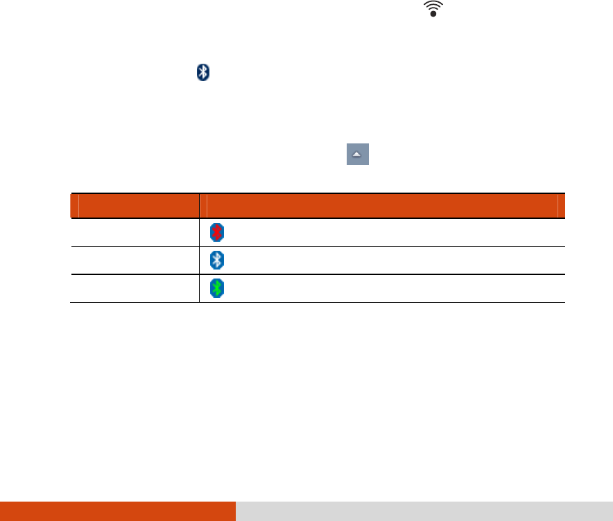
The status of the Bluetooth connection is indicated by the Bluetooth icon
located in the taskbar. (You need to tap on the taskbar to show the
hidden icons.)
Status Icon
Off (blue with red logo)
On (blue with white logo).
Connected (blue with green logo)
You can use the Bluetooth Utility to configure Bluetooth wireless
connection settings and transfer files.
Operating Your Computer 2-33
Connecting to another Bluetooth Device
1. Make sure that the Bluetooth function is enabled (as described
above).
2. Make sure that the target Bluetooth device is turned on, discoverable
and within close range. (See the documentation that came with the
Bluetooth device.)
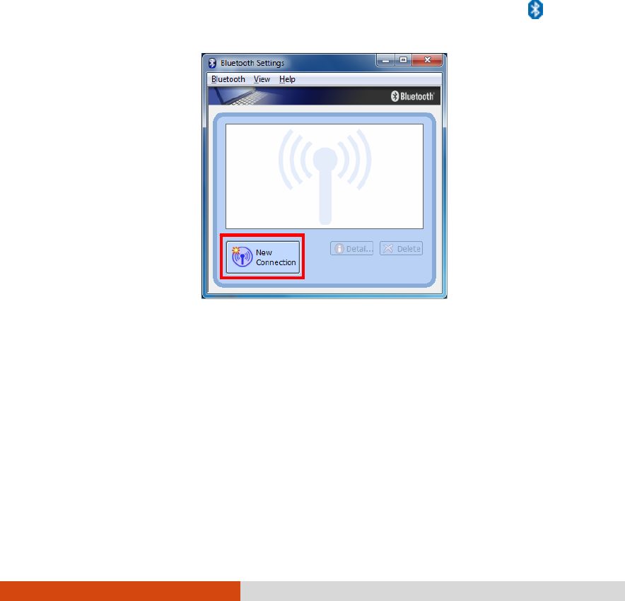
3. Start the Bluetooth utility by double-clicking the Bluetooth icon on
the taskbar and click New Connection.
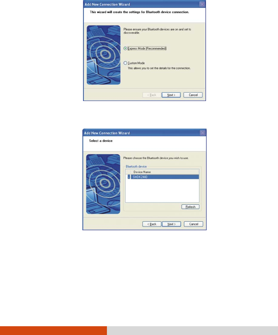
4. The Add New Connection Wizard window appears. Select Express Mode
(Recommended), and then click Next.
2-34 Operating Your Computer
5. Select the device to connect to and click Next.
6. Depending on the type of Bluetooth device that you want to connect
to, you will need to enter the pertinent information.
For detailed information on using the Bluetooth Utility, see the Bluetooth
Utility Help.

Managing Power 3-1
Chapter 3
Managing Power
Your computer operates either on external AC power or on internal
battery power.
This chapter tells you how you can effectively manage power. To
maintain optimal battery performance, it is important that you use the
battery in the proper way.

3-2 Managing Power
AC Adapter
CAUTION:
The AC adapter is designed for use with your computer only. Connecting the
AC adapter to another device can damage the adapter.
The AC power cord supplied with your computer is for use in the country
where you purchased your computer. If you plan to go overseas with the
computer, consult your dealer for the appropriate power cord.
When you disconnect the AC adapter, disconnect from the electrical outlet
first and then from the computer. A reverse procedure may damage the AC
adapter or computer.
When unplugging the connector, always hold the plug head. Never pull on the
cord.
The AC adapter serves as a converter from AC (Alternating Current) to DC
(Direct Current) power because your computer runs on DC power, but an
electrical outlet usually provides AC power. It also charges the battery
pack when connected to AC power.
The adapter operates on any voltage in the range of 100~240 V AC.

Managing Power 3-3
Battery Pack
The battery pack is the internal power source for the computer. It is
rechargeable using the AC adapter.
The operating time of a fully charged battery pack depends on how you
are using the computer. When your applications often access peripherals,
you will experience a shorter operating time.
NOTE: Care and maintenance information for the battery is provided in the
“Battery Pack Guidelines” section in Chapter 7.
Charging the Battery Pack
NOTE:
Charging will not start if the battery’s temperature is above 50C (122F) or
below -2C (28F); and the charging process will stop if the battery’s
temperature gets above 60C (140 F) or below -2C (28F). The Battery
Charge Indicator flashes green and yellow by turns to inform you of such
situation. To avoid damaging the battery, disconnect the AC adapter and wait
for the battery to return to room temperature before charging again.
During charging, do not disconnect the AC adapter before the battery has
been fully charged; otherwise you will get a prematurely charged battery.
To charge the battery pack, connect the AC adapter to the computer
and an electrical outlet. The Battery Charge Indicator ( ) on the
computer glows yellow to indicate that charging is in progress. You are
advised to keep the computer power off while the battery is being
charged. When the battery is fully charged, the Battery Charge Indicator
is off.
It takes approximately 3 hours to fully charge the Li-Ion battery pack when
the computer is off, and approximately 6 hours to fully charge the Li-Ion
battery pack when the computer is on.
3-4 Managing Power
CAUTION: After the computer has been fully recharged, do not immediately
disconnect and reconnect the AC adapter to charge it again. Doing so may
damage the battery.
NOTE: The battery level may automatically lessen due to the self-discharge
process (0.21 % per day), even when the battery pack is fully charged (100 %).
This happens no matter if the battery pack is installed in the computer.
Checking the Battery Level
NOTE: Any battery level indication is an estimated result. The actual operating
time can be different from the estimated time, depending on how you are using
the computer.
By Operating System
You can check the approximate battery level using the battery meter
function of the operating system. To read the battery level in Windows,
click the battery icon on the taskbar.
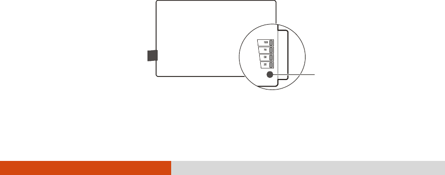
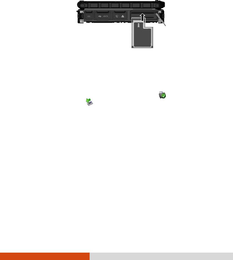
By Gas Gauge
On the exterior side of the battery pack is a gas gauge for displaying the
estimated battery charge. When the battery pack is not installed in the
computer and you want to know the battery charge, you can press the
switch with a pointed device to see the corresponding value of indicator
segment that light green.
Switch
Managing Power 3-5
The value of the corresponding green segment indicates the relative
percentage of the battery charge. The battery pack is fully discharged
when you see no segment glowing green.
Replacing the Battery Pack
CAUTION:
There is danger of explosion if the battery is incorrectly replaced. Replace the
battery only with the computer manufacturer’s optional battery packs. Discard
used batteries according to the dealer’s instructions.
Do not attempt to disassemble the battery pack.
If you often rely on battery power for a long period of time while traveling,
you may consider the purchase of an additional battery pack from your
dealer and keep it with you in a fully charged state as a backup.
To replace the battery pack, follow these steps:
1. Make sure that the computer is not turned on or connected to AC
power.
2. Locate the battery compartment on the right side of the computer.
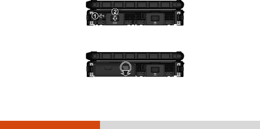
3. Slide the door lock toward the left to unlock (). Then slide the door
latch downward to open the door( ).
4. Pull on the ribbon strip to remove the battery pack.

3-6 Managing Power
5. With the ribbon strip facing outward, slide the new battery pack all the
way into the slot.
6. Close the door. Make sure the door latch clicks into place. Then, slide
the door lock toward the right.
Battery Low Signals and Actions
When the battery is low, Windows gives warning messages and the Battery
Charge Indicator ( ) blinks yellow to alert you.
Immediately save your data upon Battery Low. The remaining operating
time depends on how you are using the computer. If you are using the
audio subsystem, PC card, hard or USB flash disk, the battery might run out
of charge very quickly.
Always respond to Battery Low by connecting the AC adapter, turning off
the computer, or placing your computer in Hibernation mode. If you do
not take any action, the computer will automatically hibernate and turn
off.
NOTE: You can set up the threshold of Battery Low and actions for Windows to
take with Windows Power Options. (For more information, see Windows’ Help.)

Managing Power 3-7
Power Management
Your computer supports ACPI (Advanced Configuration and Power
Interface) for power management. The power management feature
allows you to reduce the power consumption for energy saving.
With an ACPI-compliant operating system such as Windows, power supply
to different computer components is controlled on an as-needed basis.
This allows maximum power conservation and performance at the same
time.
In general, Windows’ power management works in this way:
What... When...
Power to the hard disk is turned
off When the hard disk has been idle for a
set period.
Power to the display is turned off
When the display has been idle for a
set period.
When the entire system has been idle
for a set period.
The computer enters the
Standby/Sleep mode. The hard
disk and display are turned off
and the entire system consumes
less power.
When you manually activate the
mode.
When the entire system has been idle
for a set period.
The computer enters the
Hibernation mode. (See the next
subsection for more
information.) When you manually activate the
mode.
For detailed information on power management, see Windows’ Help.

3-8 Managing Power
Hibernation
Hibernation is a very useful feature. People frequently open many
applications when they use computers. It takes some time to get all these
applications open and running, and normally they all have to be closed
before the computer can be turned off.
When you use the hibernation feature, you do not have to close the
applications. The computer stores the state of your computer to a file on
the hard disk and then shuts down. The next time you turn on your
computer, you return to exactly where you left off.

Managing Power 3-9
Power-Saving Tips
Aside from enabling your computer’s power saving mode (see previous
section), you can do your part to maximize the battery’s operating time
by following these suggestions.
Do not disable Power Management.
Decrease the LCD brightness to the lowest comfortable level.
Shorten the length of time before Windows turn off the display.
Many USB devices use power just by being connected. If you use a
USB mouse, you can save power by disconnecting the mouse and
using the touchpad. If you use a USB flash drive, unplug it when you
are not using it.
If you work with an application that uses a PC card, exit the
application when you finish using it.
If you have a PC card installed, remove it when not in use. Some PC
cards drain power even while they are inactive.
Turn off the wireless radio if you are not using the wireless module.
Turn off the computer when you are not using it.

Expanding Your Computer 4-1
Chapter 4
Expanding Your
Computer
You can expand the capabilities of your computer by connecting other
peripheral devices. When using a device, be sure to read the instructions
accompanying the device together with the relevant section in this
chapter.
4-2 Expanding Your Computer
Connecting an External Monitor
If you want the benefits of a larger display screen with higher resolution,
you can connect an external display monitor to your computer. Follow this
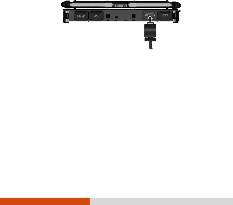
procedure to connect an external monitor:
1. Make sure that the computer is not turned on.
2. Plug the monitor’s D-type signal connector to the computer’s VGA
connector.
3. Plug one end of the monitor’s power cord into the power socket on
the monitor and the other end to an electrical outlet.
4. To use the monitor, turn on the monitor before turning on the
computer.
5. The monitor should respond by default. If not, you can switch the
display to the monitor or to both (simultaneous display), or to
multi-display by pressing the Fn+F5 hot key. In Windows, you can also
change the display through the settings in Display Properties.
6. You can change display settings through your operating system. See
your operating system documentation or online help for specific
information.
CAUTION: Do not disconnect the external monitor while the computer is in the
Standby/Sleep mode or Hibernation mode. If no external monitor is connected
when the computer resumes, the LCD might not display properly.
Expanding Your Computer 4-3
Connecting a Serial Device
Your computer has one or two serial port (depending on model) for
connecting a serial device such as a serial mouse or serial communication
device (modem).
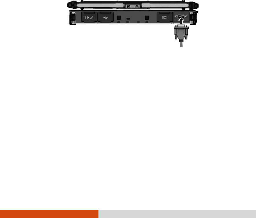
Follow this procedure to connect a serial device:
1. Make sure the computer is not turned on
2. Plug the device cable to the serial port on the rear of the computer.
3. Turn on the computer.
NOTE: Portable modems that derive power through the serial port cannot be
used with the computer. Instead, use a modem that is powered by its own internal
battery or external AC power.
4-4 Expanding Your Computer
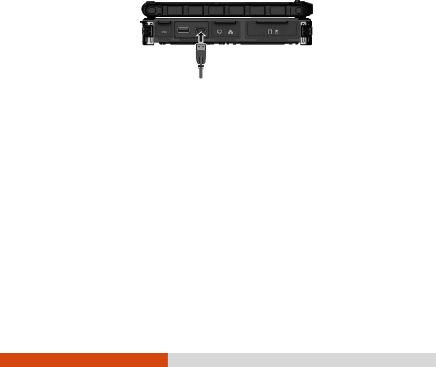
Connecting a USB Device
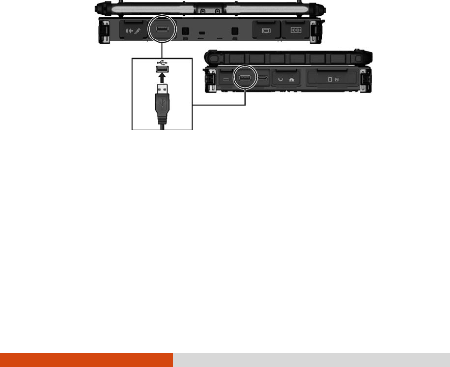
Your computer has two USB ports for connecting USB devices, such as a
digital camera, scanner, printer, modem, and mouse.
NOTE: The eSATA/USB Combo port can also function as a USB port.
The USB port support transfer rates up to 12 MB/s for USB 1.1 devices and
480 MB/s for USB 2.0 devices.
To connect a USB device, simply plug the device cable to one of the USB
ports.
Expanding Your Computer 4-5
Connecting an eSATA Device
Your computer has an eSATA/USB Combo port for connecting eSATA
devices (such as an external hard drive and external optical drive) / USB
devices (see previous section).
The port supports SATA II with transfer rate up to 3.0Gbit/s. It can provide
5V power if a certified USB-eSata combo cable is used.
To connect an external eSATA device, simply plug the device cable to the
eSATA port.
4-6 Expanding Your Computer
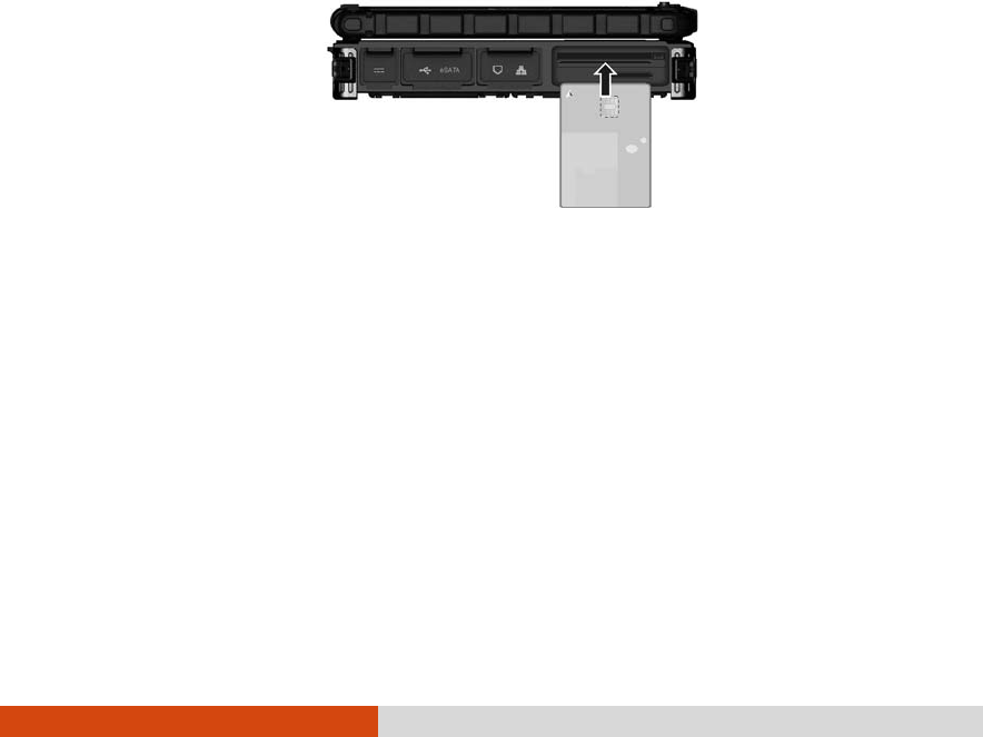
Using Smart Cards (Optional)
Your computer may have a smart card reader.
With an embedded microcontroller, smart cards have the unique ability
to store large amounts of data, carry out their own on-card functions (e.g.,
encryption and mutual authentication), and interact intelligently with a
smart card reader.
To insert a smart card:
1. Locate the smart card slot (the one without the eject button).
2. Slide the smart card, with its label and embedded computer chip
facing up into the slot.
3. When a new card is seated, use the third-party smart card software to
allow your computer to read it.
To remove a smart card:
1. Make sure that the third-party smart card software is not accessing the
smart card.
2. Pull the card out of the slot.
Expanding Your Computer 4-7
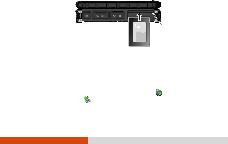
Using PC Cards
NOTE:
Some PC cards require additional system resources. Before using such PC
card, you may have to free other system resources for the PC card.
Although some PC cards can be inserted and removed without turning off the
computer, you cannot remove or install PC cards during Sleep/Standby
mode.
Your computer has one or two PC card slots that support CardBus
specifications. The slots can accommodate a type II card. Typical type II
cards are flash memory, SRAM, modem, LAN, and SCSI cards.
To insert a PC card:
1. Locate the PC card slot on the left side of the computer.
2. Slide the PC card, with its label facing up, into the slot until the eject
button pops out.
3. When a new card is seated, the computer will detect it and try to
install the appropriate driver. Follow the on-screen instructions to
complete the process.
To remove a PC card:
1. Double-click on the Safely Remove Hardware icon ( for Windows
Vista/Windows 7 or for Windows XP) found on the Windows taskbar
and the Safely Remove Hardware window appears on screen.
Eject button

4-8 Expanding Your Computer
2. Select (highlight) the PC card from the list to disable the card.
3. Push the eject button and the card will slide out slightly.
4. Pull the card out of the slot.
Expanding Your Computer 4-9
Using ExpressCards (Optional)
NOTE: The ExpressCard interface is not compatible with the PC card interface.
Your computer may have an ExpressCard slot.
ExpressCard supports the PCI Express and USB 2.0 serial data interfaces
(supporting speeds of up to 2.5 Gbps and 480 Mbps respectively),
improving speed in data transfer while conserving power usage.
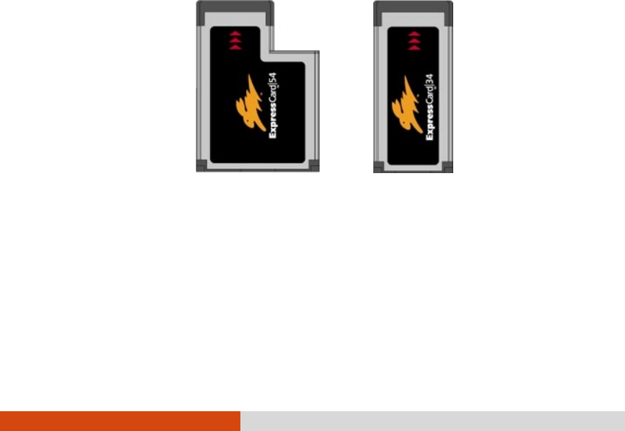
The ExpressCard slot can accommodate a 54 mm (ExpressCard/54) or
34 mm (ExpressCard/34) wide ExpressCard. Typical ExpressCards support a
very extensive range of applications including memory, wired and wireless
communication cards, and security devices.
Shown next are the appearances of ExpressCards for your reference.
ExpressCard/54 ExpressCard/34
To insert an ExpressCard:
1. Locate the ExpressCard slot on the left side of the computer (the
upper one).
4-10 Expanding Your Computer
2. Slide the ExpressCard, with its label facing up, all the way into the slot
until the rear connectors click into place.
3. When a new card is seated, the computer will detect it and try to
install the appropriate driver. Follow the on-screen instructions to
complete the process.
To remove an ExpressCard:
1. Double-click on the Safely Remove Hardware icon ( for Windows
Vista/Windows 7 or for Windows XP) found on the Windows taskbar
and the Safely Remove Hardware window appears on screen.
2. Select (highlight) the ExpressCard from the list to disable the card.
3. Push the eject button and the card will slide out slightly.
4. Pull the card out of the slot.
Eject button
Expanding Your Computer 4-11
Using the SD Card Reader
NOTE:
If your hard disk is divided into several drives, make sure that all drives have
been formatted before using the Card Reader. Otherwise, you may encounter
problems when using the Card Reader.
You can use only storage cards. Your Card Reader does not support cards
with I/O (input/output) functions such as a wireless network card or Bluetooth
card.
Your computer has a Card Reader. The Card Reader is a small drive for
reading from and writing to removable storage cards (or called memory
cards). The Card Reader supports Secure Digital (SD) cards.
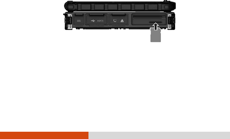
To insert a storage card:
1. Locate the Card Reader slot on the left side of the computer.
2. Align the card with its connector pointing to the slot and its label
facing up. Slide the card into the slot until it reaches the end.
3. Windows will detect the card and assign it a drive name.
To remove a storage card:
1. Double-click My Computer.
2. Right-click the drive with the card and select Eject.
3. Push the card to release and then pull the card out of the slot.
4-12 Expanding Your Computer
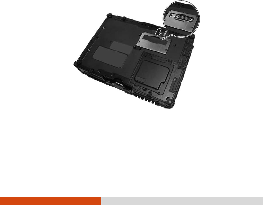
Using the Port Replicator (Optional)
NOTE: To use the port replicator, the Vehicle Dock driver supplied with your
computer must be installed.
A port replicator is available as an option. This device eliminates the
hassles of having you connect and disconnect the various cables when
carrying your computer around and allows a variety of peripherals to be
connected including a headphone or microphone, etc. The port
replicator connects to the expansion bus connector at the bottom of your
computer.
1. Slide open the expansion bus connector cover.
2. Connect your port replicator to the expansion bus connector.
For more detailed information, refer to the instructions supplied with the
port replicator.
Expanding Your Computer 4-13
System Memory Upgrade
You can upgrade your computer by changing system memory to a
maximum of 8 GB on the DDR3 SO-DIMM slot.
CAUTION: RAM modules are extremely sensitive to static electricity. There are
cases where static electricity generated by the human body has adversely
affected such modules. When inserting or removing a RAM module, do not touch
the terminals or internal components, insert objects other than the module, or
allow foreign particles to enter. Doing so has been known to cause damage, fire,
or electrical shock.
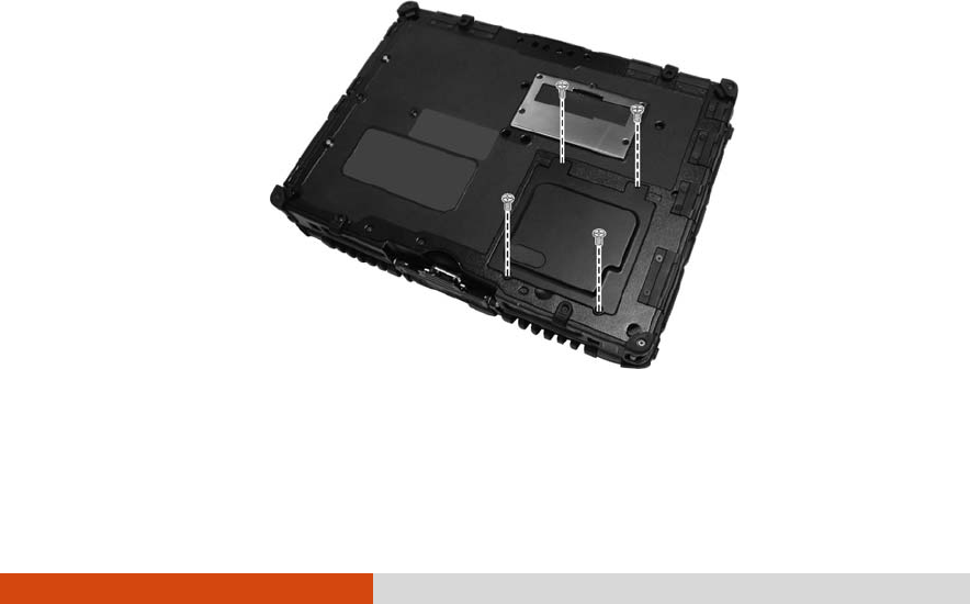
To install the RAM module:
1. Remove the battery pack (see chapter 3) and make sure that the
computer is not connected to AC power.
2. Carefully place the computer upside down.
3. Remove the four screws to open the compartment cover.
4-14 Expanding Your Computer
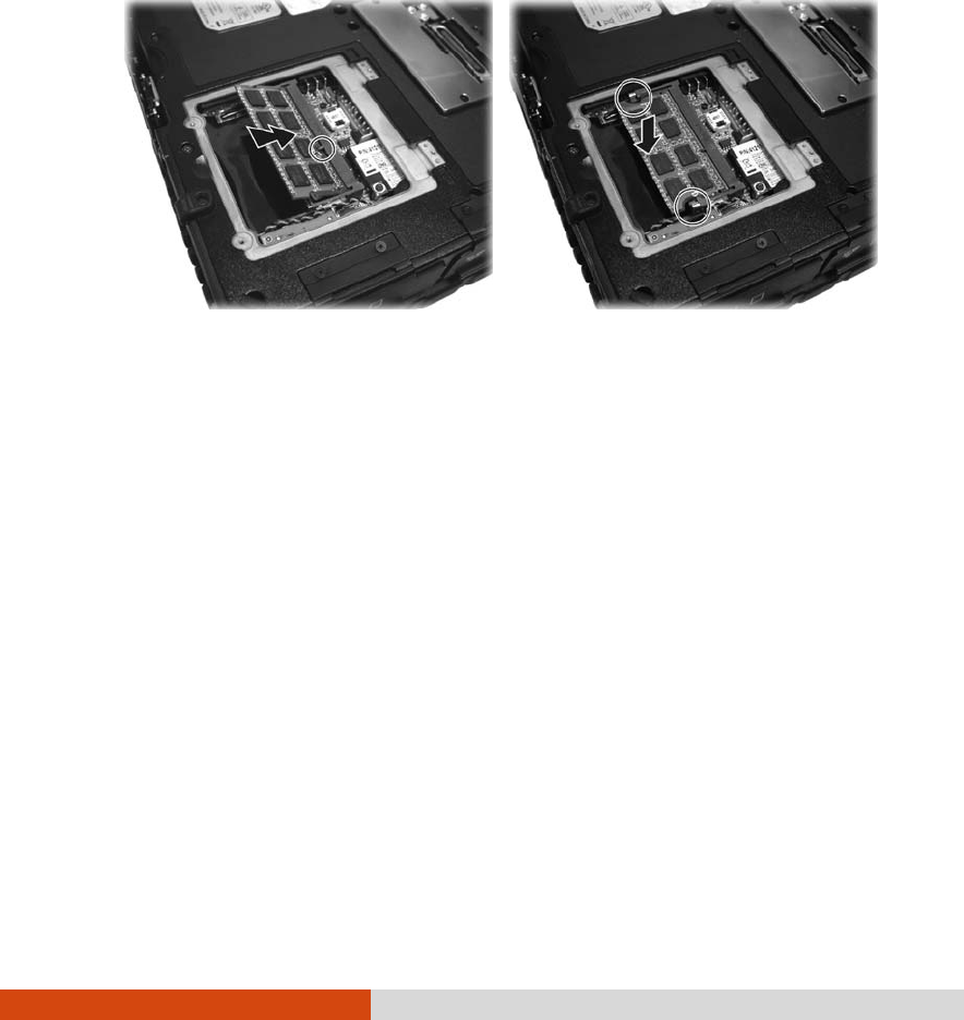
4. To install the RAM module, match the module's notched part with the
socket's projected part and firmly insert the module into the socket at
a 20-degree angle. Then push down until the retaining clips lock the
module into position.
CAUTION: If the RAM module is difficult to insert or difficult to push down, do not
force it. Check once more to ensure that the module is positioned correctly.
5. Close the compartment cover and secure with four screws.

Using BIOS Setup and System Recovery 5-1
Chapter 5
Using BIOS Setup and
System Recovery
BIOS Setup Utility is a program for configuring the BIOS (Basic Input/ Output
System) settings of the computer. BIOS is a layer of software, called
firmware, that translates instructions from other layers of software into
instructions that the computer hardware can understand. The BIOS
settings are needed by your computer to identify the types of installed
devices and establish special features.
System Recovery reinstalls Windows to your computer and restores it to the
factory default status.
This chapter tells you how to use the BIOS Setup and System Recovery.

5-2 Using BIOS Setup and System Recovery
BIOS Setup
When and How to Use
You need to run BIOS Setup Utility when:
You see an error message on the screen requesting you to run BIOS
Setup Utility.
You want to restore the factory default BIOS settings.
You want to modify some specific settings according to the hardware.
You want to modify some specific settings to optimize the system
performance.
To run BIOS Setup Utility, press the F2 key when the prompt appears on the
screen during the system startup. The prompt shows up on the screen for
only a few seconds. You must press the F2 key quickly. The BIOS Setup
Utility main screen appears as shown next.
Main Advanced Security Boot Exit
Model:
SATA HDD:
System Time:
System Date:
Processor Info:
Installed System Memory:
System BIOS Version:
KBC/EC BIOS Version:
LAN MAC Address:
Serial Number:
V200-X
[INTEL SSDSA2M080G2GC] 80026MB
[16:33:08]
[07/05/2010]
Intel(R)Core(TM)i7 CPU U620@2.00GHz
2048MB
R1.01
R1.01u
00-22-20-0A-98-B4
12231241241324
F1 Help ↑↓ Select Item -/+ Change Values F9 Setup Defaults
Esc Exit ←→ Select Menu Enter Select Sub-Menu F10 Save and Exit
1
6

Using BIOS Setup and System Recovery 5-3
In general, you can use the arrow keys to move around and + / – keys to
change the setup values. Keyboard information can be found at the
bottom of the screen.
NOTE:
The BIOS Setup Utility screens shown in this chapter are for your reference
only. The actual items or settings on your computer may differ.
The BIOS Setup Utility program may have been updated after the publication
of this manual.
The settings you select in your operating system might override similar
settings in BIOS Setup Utility.
Main Menu
The Main menu contains the system date and time settings as well as
shows the basic configuration of the system.
Main Advanced Security Boot Exit
Model:
SATA HDD:
System Time:
System Date:
Processor Info:
Installed System Memory:
System BIOS Version:
KBC/EC BIOS Version:
LAN MAC Address:
Serial Number:
V200-X
[INTEL SSDSA2M080G2GC] 80026MB
[16:33:08]
[07/05/2010]
Intel(R)Core(TM)i7 CPU U620@2.00GHz
2048MB
R1.01
R1.01u
00-22-20-0A-98-B4
12231241241324
F1 Help ↑↓ Select Item -/+ Change Values F9 Setup Defaults
Esc Exit ←→ Select Menu Enter Select Sub-Menu F10 Save and Exit
System Time sets the system time.
System Date sets the system date.
1
6
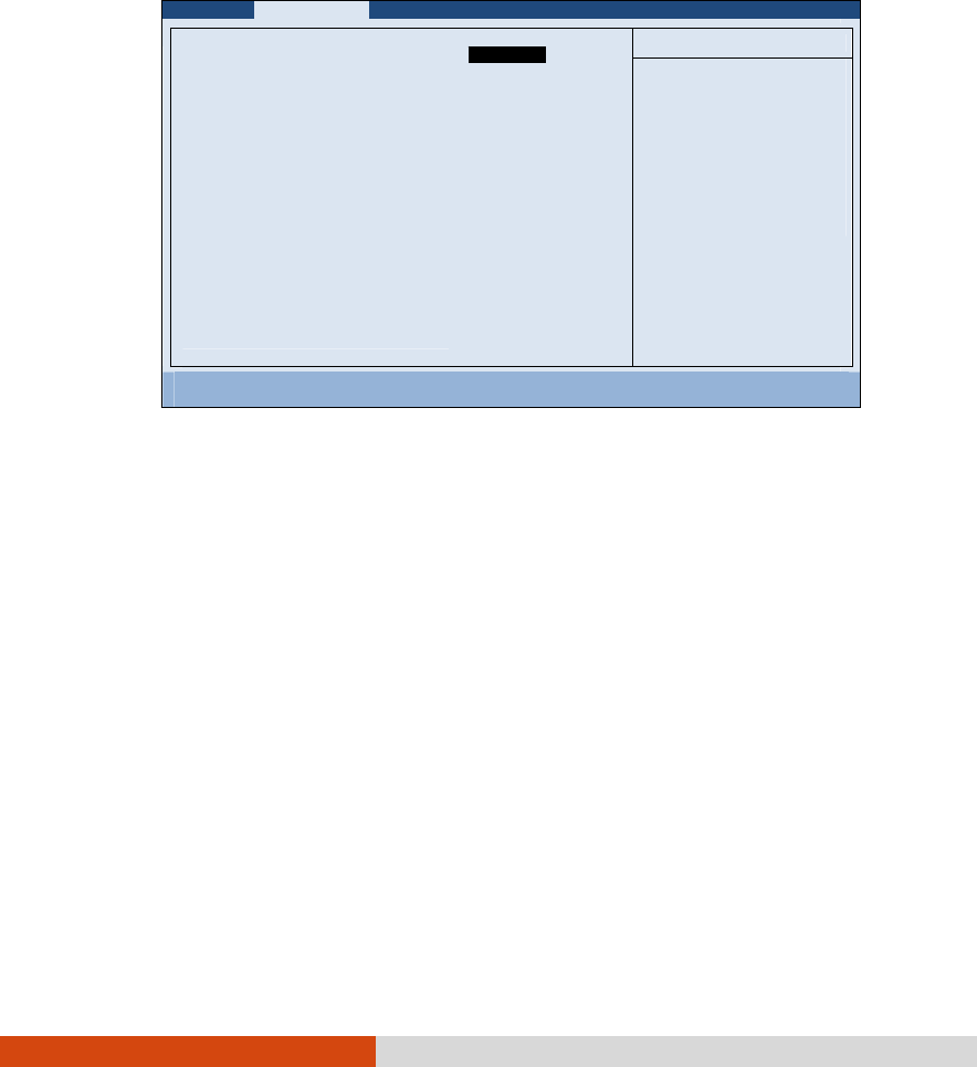
5-4 Using BIOS Setup and System Recovery
Advanced Menu
The Advanced menu contains the advanced settings as shown next.
Main Advanced Security Boot Exit
Item Specific Help
Japanese Keyboard:
SATA Mode
Total Graphics Memory:
USB Wake-Up From S3
High Brightness Thermal:
TouchScreen:
Serial port COM1:
Serial port COM2:
Serial port COM4:
Boot-time Diagnostic Screen:
Wake-On-LAN(WOL)
Turbo Mode
Intel Trusted Execution
Intel AMT Setup Prompt:
[Disabled]
[AHCI]
[MaxDVMT]
[Disabled]
[Disabled]
[Enabled]
[Enabled]
[Enabled]
[Enabled]
[Disabled]
[Disabled]
[Enabled]
[Disabled]
[Enabled]
Support Japanese
Keyboard
F1 Help ↑↓ Select Item -/+ Change Values F9 Setup Defaults
Esc Exit ←→ Select Menu Enter Select Sub-Menu F10 Save and Exit
Japanese Keyboard enables support for the Japanese keyboard.
SATA Mode sets the mode to enhanced AHCI (Advanced Host Controller
Interface) or IDE. Turbo memory feature works only when the SATA AHCI
mode is enabled.
Total Graphics Memory sets the amount of total graphics memory
(pre-allocated + fixed + DVMT) for use by the internal graphics device.
USB Wake-Up From S3 allow a USB device activity to wake up the system
from S3 (Sleep) state.
High Brightness Thermal allows dynamic control of maximum LCD brightness
level according to the ambient temperature. This helps protect the LCD
under over-heating situations.
D
i
sab
l
ed

Using BIOS Setup and System Recovery 5-5
Digitizer Type or TouchScreen (actual item shown depends on your model)
Digitizer Type allows you to select the type of digitizer you are using.
TouchScreen allows you to unconditionally disable it when set at
Disabled.
Serial Port COM1/COM2/COM4 allows you to unconditionally disable it when set
at Disabled.
Boot-time Diagnostic Screen allows you to display the diagnostic screen
during system boot-up.
Wake-On-LAN (WOL) allow a LAN activity to wake up the system from S3
(Sleep) state.
Turbo Mode enables or disables Processor Turbo Mode.
Intel Trusted Execution enables utilization of additional hardware
capabilities provided by Intel® Trusted Execution Technology.
Intel AMT Setup Prompt sets if the prompt for entering Intel AMT Setup
appears during POST. If disabled, you cannot enter Intel AMT Setup.
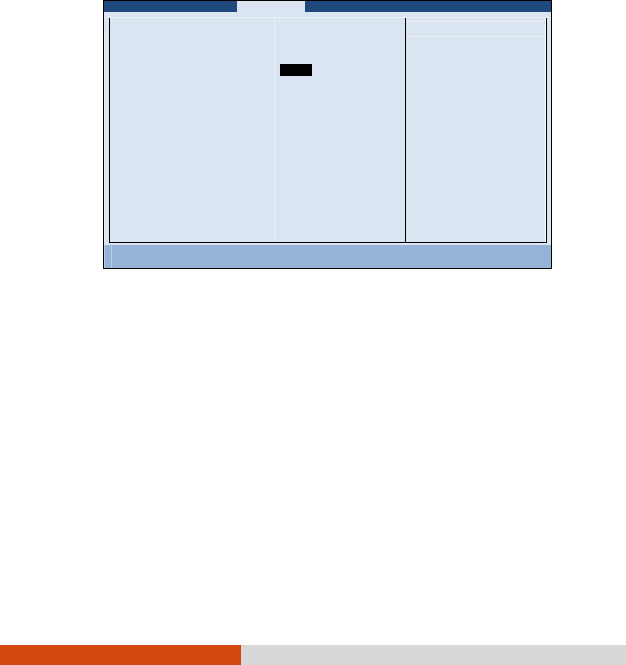
5-6 Using BIOS Setup and System Recovery
Security Menu
The Security menu contains the security settings, which safeguard your
system against unauthorized use.
Main Advanced Security Boot Exit
Item Specific Help
Supervisor Password Is:
User Password Is:
Set Supervisor Password:
Set User Password
Password on boot:
TPM Support
Set
Clear
[Enter]
[Enter]
[Disabled]
[Disabled]
Supervisor Password
c
ontrols access to the
setup utility.
F1 Help ↑↓ Select Item -/+ Change Values F9 Setup Defaults
Esc Exit ←→ Select Menu Enter Select Sub-Menu F10 Save and Exit
Supervisor/User Password Is shows whether you have set the supervisor/user
password or not for the system.
Set Supervisor/User Password sets the supervisor/user password. When typing
the password, first make sure that Num Lock is off, and then type the
password in the entry fields and press Enter. Confirm your password by
typing it again and pressing Enter. You can set the supervisor/user
password to be required for starting up the system and/or entering BIOS
Setup.
NOTE:
You can set the user password only when the supervisor password has been
set.
If both the administrator and user passwords are set, you can enter any of
them for starting up the system and/or entering BIOS Setup. However, the
user password only allows you to view/change the settings of certain items.
E
nter

Using BIOS Setup and System Recovery 5-7
Password on Boot allows you to enable or disable the entering of password
for booting up your system. Once the password is successfully set and this
item is enabled, it is required for booting up the system.
TPM Support enables or disables TPM support. TPM (Trusted Platform
Module) is a component on your computer’s mainboard that is
specifically designed to enhance platform security by providing a
protected space for key operations and other security critical tasks.
NOTE:
To use the TPM feature, the TPM driver supplied with your computer must be
installed.
The next two items Current TPM State and Change TPM State would only appear
if the item TPM Support is set at Enabled.
Current TPM State shows the current TPM state.
Change TPM State allows you to select between No Change, Clear,
Deactivate & Disable, and Enable & Activate.
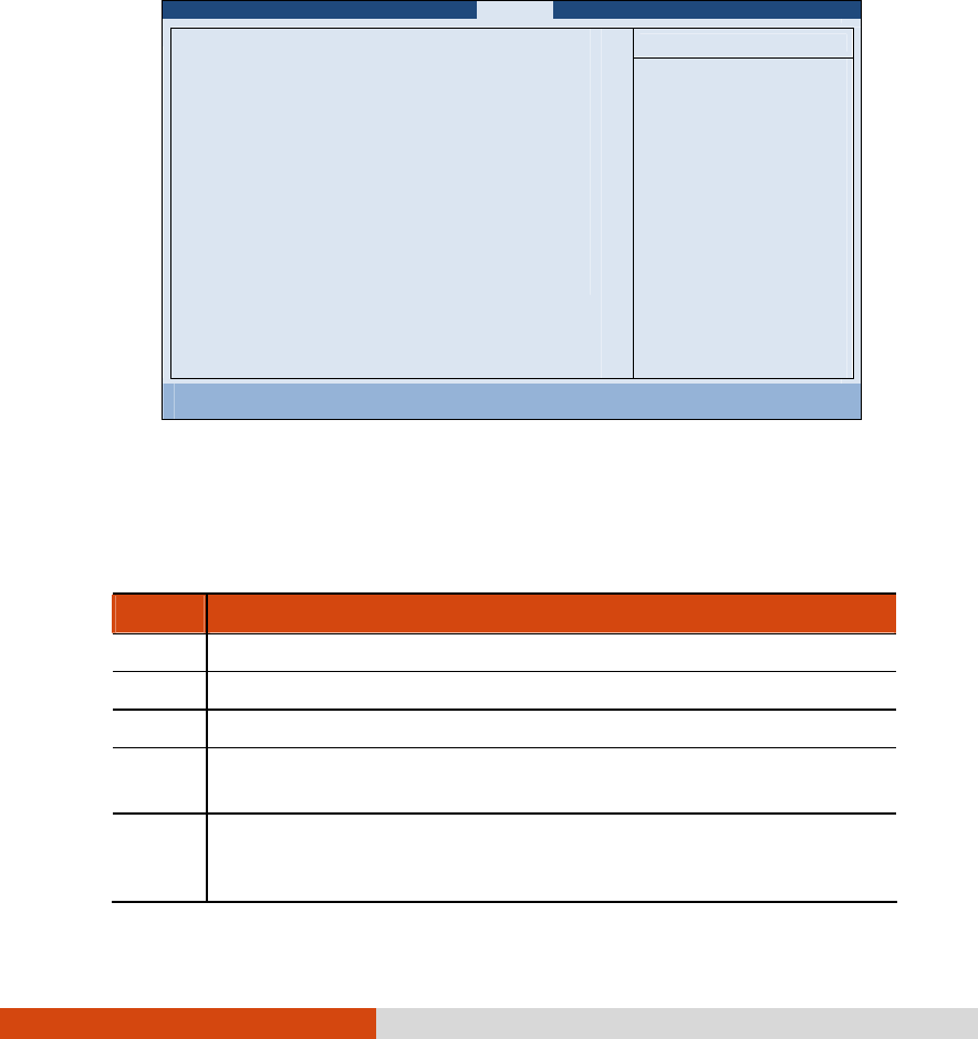
5-8 Using BIOS Setup and System Recovery
Boot Menu
The Boot menu sets the sequence of the devices to be searched for the
operating system.
Main Advanced Security Boot Exit
Item Specific Help
Boot priority order:
1: USB FDC:
2: SATA HDD: INTEL SSDSA2M080G2GC – (S1)
3: USB KEY:
4: USB HDD:
5: LAN BOOT: IBA GE Slot 00C8 v1338
6:
7:
8:
Excluded from boot order:
: USB CDROM:
Keys used to view or
configure devices:
Up and Down arrows
select a device.
<+> and <-> moves the
device up or down.
<f> and <r> specifies
the device fixed or
removable
<x> exclude or include
the device to boot.
<Shift + 1> enables or
disables a device.
<1 – 4> Loads default
boot sequence.
F1 Help ↑↓ Select Item -/+ Change Values F9 Setup Defaults
Esc Exit ←→ Select Menu Enter Select Sub-Menu F10 Save and Exit
The bootable devices will be automatically detected during POST and
shown here, allowing you to set the sequence that the BIOS uses to look for
a device from which to load the OS. Below is a brief description of
keyboard usage:
Key Function
, Selects (highlight) a boot device.
+, – Changes the boot sequence.
1 to 4 Loads the default boot sequence.
X Moves the highlighted boot device from the “Boot priority
order” list to the “Excluded from boot order” list, and vice versa.
Shift+1 Deactivates/activates the highlighted boot device on the
“Boot priority order” list. When a device has been deactivated,
an “!” (exclamation) symbol appears beside the item and
Using BIOS Setup and System Recovery 5-9
system will bypass it when detecting boot device during POST.
Exit Menu
The Exit menu displays ways of exiting BIOS Setup Utility. After finishing with
your settings, you must save and exit so that the changes can take effect.
Main Advanced Security Boot Exit
Item Specific Help
Exit Saving Changes
Exit Discarding Changes
Load Setup Defaults
Discard Changes
Save Changes
Exit System Setup and
save your changes to
CMOS.
F1 Help ↑↓ Select Item -/+ Change Values F9 Setup Defaults
Esc Exit ←→ Select Menu Enter Select Sub-Menu F10 Save and Exit
Exit Saving Changes saves the changes you have made and exits BIOS Setup
Utility.
Exit Discarding Changes exits BIOS Setup Utility without saving the changes
you have made.
Load Setup Defaults loads the factory default values for all the items.
Discard Changes restores the previous values for all the items.
Saves Changes saves the changes you have made.

5-10 Using BIOS Setup and System Recovery
System Recovery
Use System Recovery when:
Your Windows operating system does not start at all.
You want to restore the factory default Windows settings.
WARNING: Using this feature will reinstall Windows to your system. All data on
the hard disk drive will be lost.
To run System Recovery:
1. During system startup when the following screen appears, press Ctrl +
Alt + F2 keys for four seconds.
2. The message This will help you reinstall Windows to the whole HDD
to factory default. All data on HDD will be lost appears on the
screen to ask if you want to access System Recovery. Type 1 to
continue.
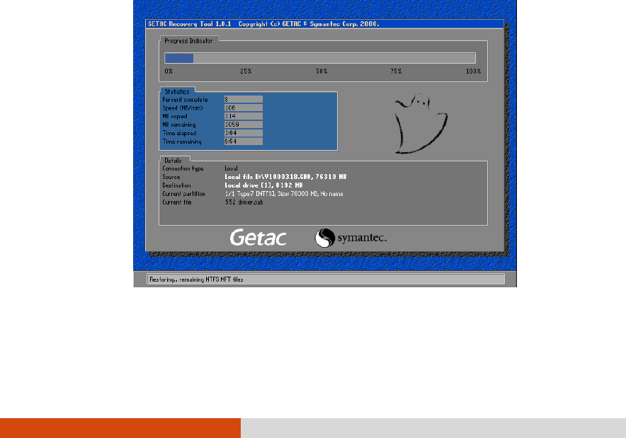
Using BIOS Setup and System Recovery 5-11
3. A warning message appears as follows:
****************************************
You must accept the following terms before performing the recovery
process:
1. The recovery software is solely the purpose of reinstalling or
restoring software associated with the hard disk of this operating
Getac machine.
2. Except the above, no other use is granted hereunder.
****************************************
(1)Yes, I agree to the provisions of this agreement and wish to
continue.
(0)No, I do not agree to the provisions of this agreement and do
not wish to continue.
Type 1 to continue.
4. Type Y when the message Are you sure you want to recover now?
(Y)Yes (N)No appears onscreen. The following screen appears and
system will perform the recovery process and Windows operating
system will be re-installed to its default setting:
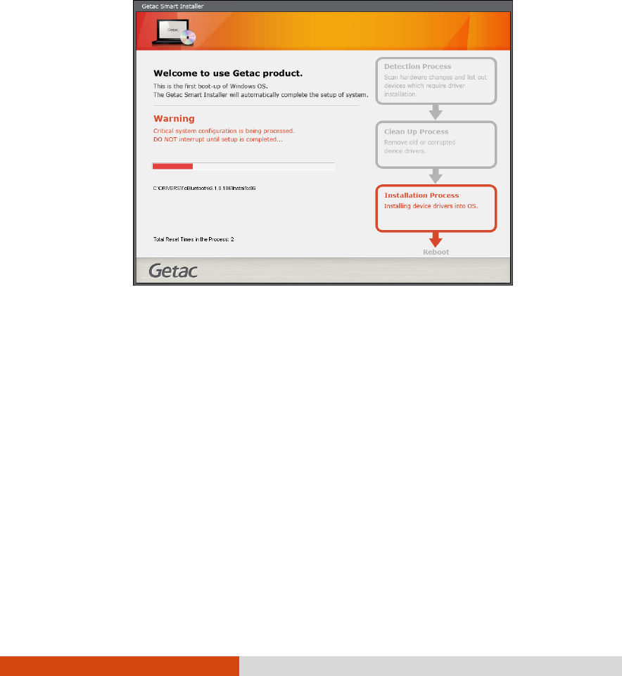
5-12 Using BIOS Setup and System Recovery
5. After the recovery process has been completed successfully, the GSI
(Getac Smart Installer) screen is displayed at the first boot-up of
Windows operating system.
6. GSI will automatically perform system hardware detection and driver
installation. After GSI has completed the whole process successfully,
system will reboot.

Installing Software Drivers and Utilities 6-1
Chapter 6
Installing Software
Drivers and Utilities
To take full advantage of the unique features of your computer, drivers
and utilities must be installed.
If you purchased the computer with Windows pre-installed, your dealer
may have already installed the drivers and utilities. If not, you need to
install them using the disc supplied with your computer.
This chapter describes how to install the drivers and utilities.
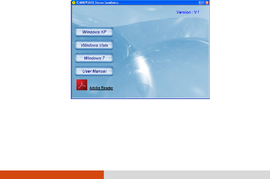
6-2 Installing Software Drivers and Utilities
How to Use the Driver Disc
NOTE:
The drivers may have been updated after this manual was published. For
driver upgrade, please contact your dealer.
This disc supports Windows XP, Windows Vista, and Windows 7.
The available items may differ according to your computer model. Some
items are for select models only.
Do not remove the driver disc when installing the driver.
An autorun program is provided on the driver disc to help you easily install
the drivers. As you insert the disc, the autorun program automatically
starts. If you need to start the program manually, run the Autorun.exe
program from the driver disc.
When the following screen appears, select Windows XP, Windows Vista, or
Windows 7 based on the operating system installed.
The User Manual item on the screen allows you to view the User Manual with
Adobe Acrobat Reader. If you do not have Adobe Acrobat Reader on
your computer, install the program by clicking Adobe Reader.
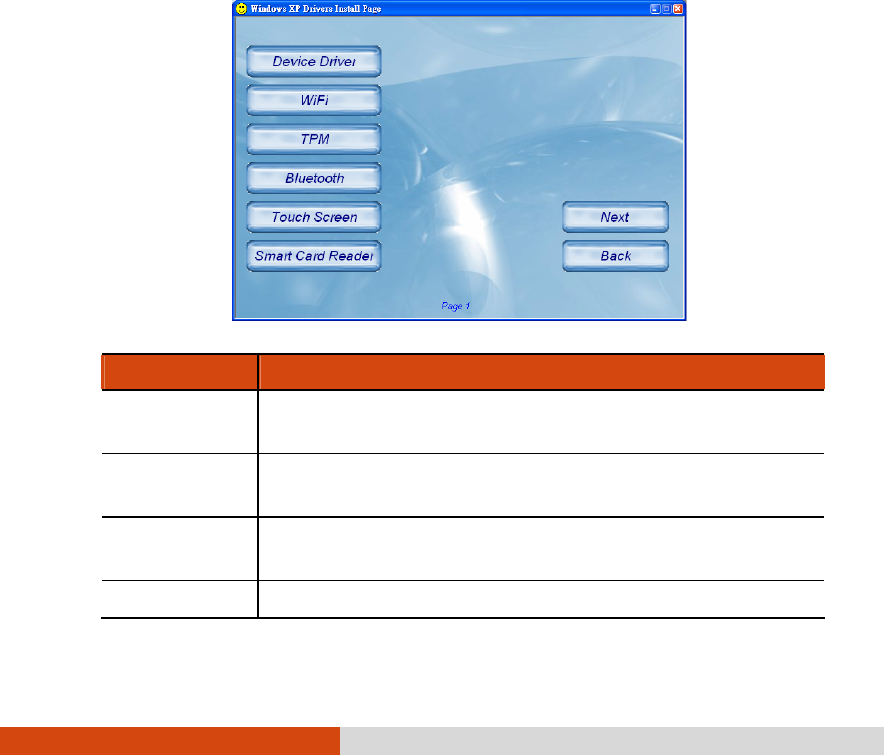
Installing Software Drivers and Utilities 6-3
Installation for Windows XP
After selecting the operating system Windows XP, the driver installation
menu appears. To install a driver, just click the particular button and follow
the onscreen instructions to complete the installation.
CAUTION: Follow the sequence of the buttons to install the drivers.
Drivers on the First Page
Item Description
Device Driver Ensures the full function of the other drivers. Install this
main driver before installing the other drivers.
WiFi Installs the WLAN driver/utility for wireless network
connection.
TPM Installs the TPM driver/utility for using the TPM (Trusted
Platform Module) support for security.
Bluetooth Installs the Bluetooth driver/utility for using the Bluetooth
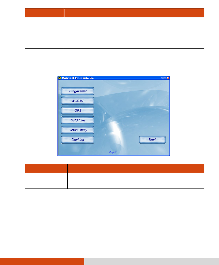
6-4 Installing Software Drivers and Utilities
feature (select models only).
Item Description
Touch Screen Installs the touchscreen driver/utility for using the
touchscreen feature (select models only).
Smart Card
Reader Installs the SmartCard driver for accessing SmartCards
(select models only).
Drivers on the Second Page
Item Description
Finger print Installs the driver/utility for using the finger print feature
(select models only).
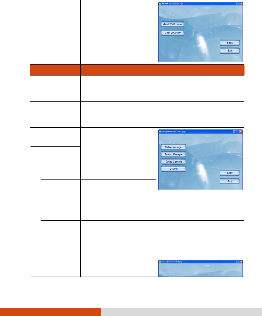
Installing Software Drivers and Utilities 6-5
WCDMA Brings up a submenu as
shown on the right.
Install the two items for
using the 3G feature
(select models only).
Item Description
GPS Installs the GPS driver for using the GPS feature (select
models only). The instructions for installing the GPS driver
will appear.
GPS Filter Works with the previous item. You must install this driver
after installing the above driver to complete the GPS
driver installation.
Getac Utility Brings up a submenu as
shown on the right.
Getac Manager
Installs the G-Manager
utility that manages and
configures various
system resources.
Button
Manager Installs the Button
Manager utility that can
customize your
computer’s quick
buttons.
Getac Camera Installs the G-Camera Lite utility that you can use to
take pictures using your computer (select models only).
V-GPS Installs the V-GPS utility that displays GPS status (select
models only).
Docking Brings up a submenu as
shown on the right.

6-6 Installing Software Drivers and Utilities
Video Capture Installs the video
capture driver.
USB to COM Installs the USB-to-COM
driver.
USB to LAN Installs the USB-to-LAN
driver.
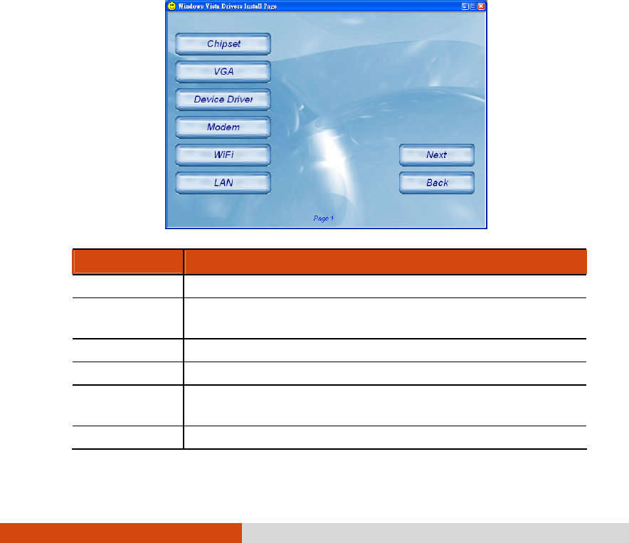
Installing Software Drivers and Utilities 6-7
Installation for Windows Vista
After selecting the operating system Windows Vista, the driver installation
menu appears. To install a driver, just click the particular button and follow
the onscreen instructions to complete the installation.
CAUTION: Follow the sequence of the buttons to install the drivers.
Drivers on the First Page
Item Description
Chipset Installs the chipset driver.
VGA Installs the VGA driver for full functionality of the video
subsystem.
Device Driver Installs the AHCI, vPro, PCI7612, and audio drivers.
Modem Installs the modem driver.
WiFi Installs the WLAN driver/utility for wireless network
connection.
LAN Installs the LAN driver for Ethernet network connection.
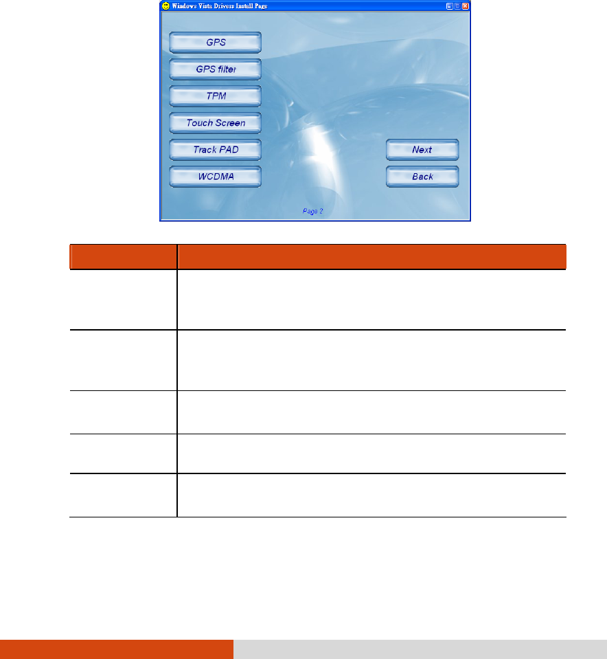
6-8 Installing Software Drivers and Utilities
Drivers on the Second Page
Item Description
GPS Installs the GPS driver for using the GPS feature (select
models only). The instructions for installing the GPS driver
will appear.
GPS Filter Works with the previous item. You must install this driver
after installing the above driver to complete the GPS
driver installation.
TPM Installs the TPM driver/utility for using the TPM (Trusted
Platform Module) support for security.
Touch Screen Installs the touchscreen driver/utility for using the
touchscreen feature (select models only).
Track PAD Installs the touchpad driver to take full advantage of the
touchpad feature.
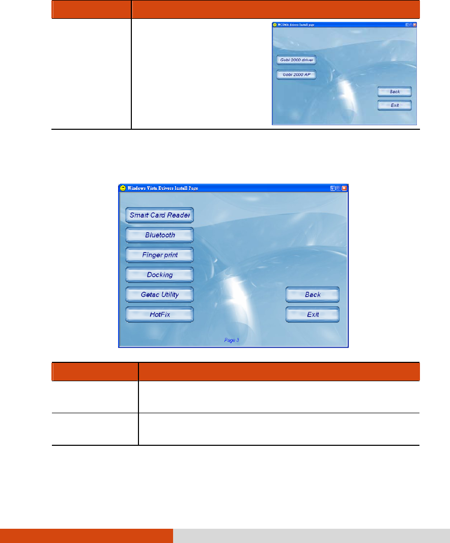
Installing Software Drivers and Utilities 6-9
Item Description
WCDMA Brings up a submenu as
shown on the right.
Install the two items for
using the 3G feature
(select models only).
Drivers on the Third Page
Item Description
Smart Card Reader Installs the SmartCard driver for accessing SmartCards
(select models only).
Bluetooth Installs the Bluetooth driver/utility for using the Bluetooth
feature (select models only).
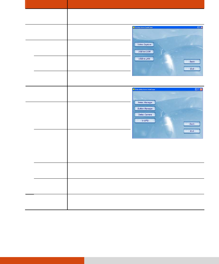
6-10 Installing Software Drivers and Utilities
Item Description
Finger print Installs the driver/utility for using the finger print feature
(select models only).
Docking Brings up a submenu as
shown on the right.
Video Capture Installs the video
capture driver.
USB to COM Installs the USB-to-COM
driver.
USB to LAN Installs the USB-to-LAN
driver.
Getac Utility Brings up a submenu as
shown on the right.
Getac Manager
Installs the G-Manager
utility that manages and
configures various system
resources.
Button
Manager Installs the Button
Manager utility that can
customize your
computer’s quick
buttons.
Getac Camera Installs the G-Camera Lite utility that you can use to
take pictures using your computer (select models only).
V-GPS Installs the V-GPS utility that displays GPS status (select
models only).
Hotfix Allows you to perform the necessary fix(es) for the
computer devices.
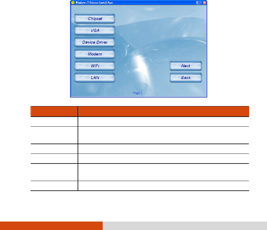
Installing Software Drivers and Utilities 6-11
Installation for Windows 7
After selecting the operating system Windows 7, the driver installation
menu appears. To install a driver, just click the particular button and follow
the onscreen instructions to complete the installation.
CAUTION: Follow the sequence of the buttons to install the drivers.
Drivers on the First Page
Item Description
Chipset Installs the chipset driver.
VGA Installs the VGA driver for full functionality of the video
subsystem.
Device Driver Installs the AHCI, vPro, PCI7612, and audio drivers.
Modem Installs the modem driver.
WiFi Installs the WLAN driver/utility for wireless network
connection.
LAN Installs the LAN driver for Ethernet network connection.
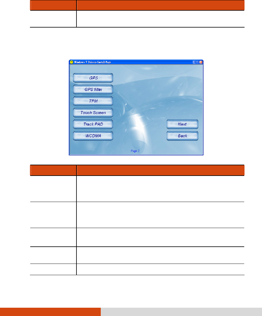
6-12 Installing Software Drivers and Utilities
Item Description
Touch Screen Installs the touchscreen driver/utility for using the
touchscreen feature (select models only).
Drivers on the Second Page
Item Description
GPS Installs the GPS driver for using the GPS feature (select
models only). The instructions for installing the GPS driver
will appear.
GPS Filter Works with the previous item. You must install this driver
after installing the above driver to complete the GPS
driver installation.
TPM Installs the TPM driver/utility for using the TPM (Trusted
Platform Module) support for security.
Touch Screen Installs the touchscreen driver/utility for using the
touchscreen feature (select models only).
Track PAD Installs the touchpad driver to take full advantage of the
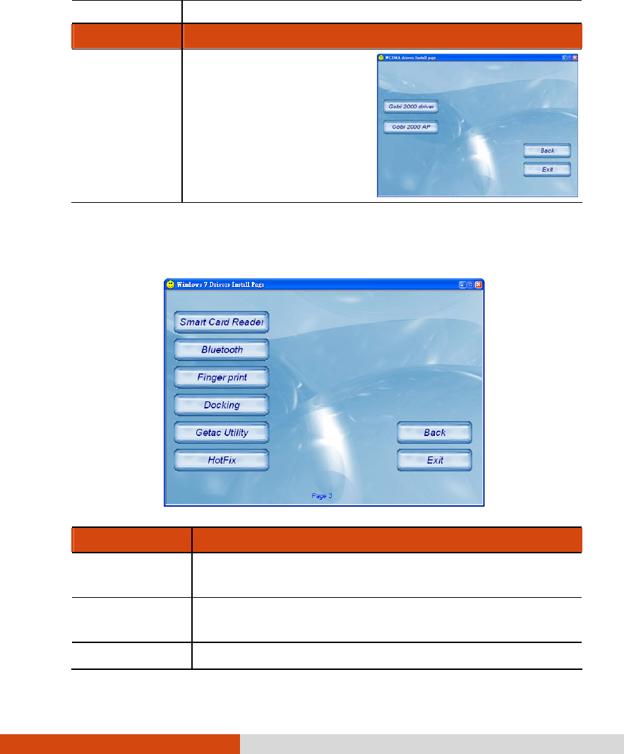
Installing Software Drivers and Utilities 6-13
touchpad feature.
Item Description
WCDMA Brings up a submenu as
shown on the right.
Install the two items for
using the 3G feature
(select models only).
Drivers on the Third Page
Item Description
Smart Card Reader Installs the SmartCard driver for accessing SmartCards
(select models only).
Bluetooth Installs the Bluetooth driver/utility for using the Bluetooth
feature (select models only).
Finger print Installs the driver/utility for using the finger print feature
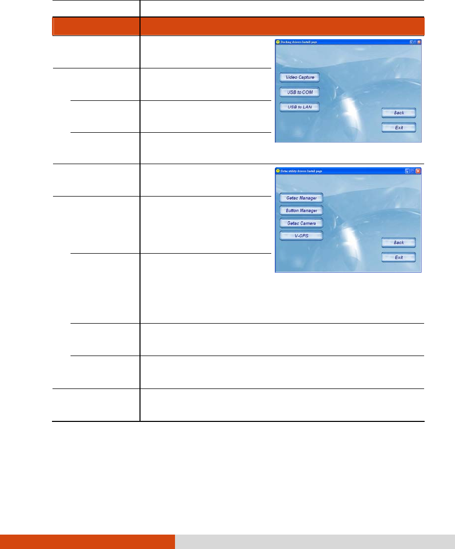
6-14 Installing Software Drivers and Utilities
(select models only).
Item Description
Docking Brings up a submenu as
shown on the right.
Video Capture Installs the video
capture driver.
USB to COM Installs the USB-to-COM
driver.
USB to LAN Installs the USB-to-LAN
driver.
Getac Utility Brings up a submenu as
shown on the right.
Getac Manager
Installs the G-Manager
utility that manages and
configures various system
resources.
Button
Manager Installs the Button
Manager utility that can
customize your
computer’s quick
buttons.
Getac Camera Installs the G-Camera Lite utility that you can use to
take pictures using your computer (select models only).
V-GPS Installs the V-GPS utility that displays GPS status (select
models only).
Hotfix Allows you to perform the necessary fix(es) for the
computer devices.

Using Getac Software 7-1
Chapter 7
Using Getac Software
Getac software is provided for enhanced capabilities and management.
This chapter describes how to use the software.

7-2 Using Getac Software
Using G-Manager
G-Manager is a unified user interface utility that allows you to manage
and configure the following:
System
Battery
ECO (economy mode)
Light Sensor
Ignition
Monitoring
GPS Status
To start up G-Manager, do one of the following:
Click Start All Programs Getac Utility, or
Right-click on the Getac Utility icon ( ) located on the taskbar and
click G-Manager.
The screen as shown next appears.
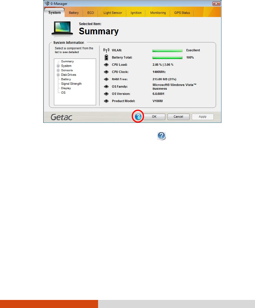
Using Getac Software 7-3
For detailed descriptions of G-Manager, click .
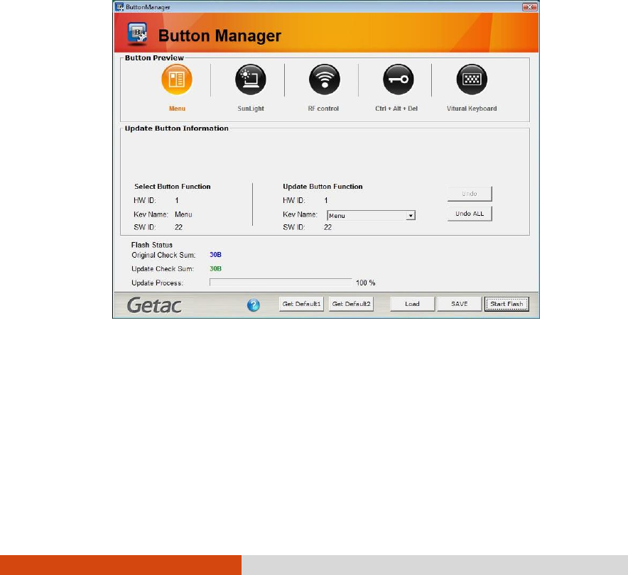
7-4 Using Getac Software
Using Button Manager
The five quick buttons located on the front of your computer come with
predefined functions. You can use Button Manager to re-define the
buttons.
1. Click Start Programs Button Manager Button Manager. The following
screen appears.
2. Select the button to re-define.
3. Under the Update Button Function click the Key Name dropdown list to
select a new button function.
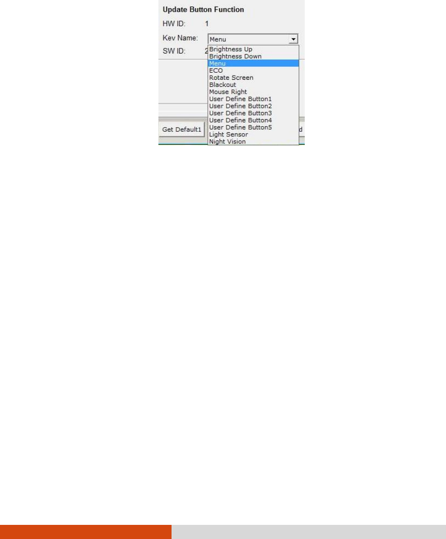
Using Getac Software 7-5
4. Repeat the steps for the other buttons that you want to re-define.
5. Click Save to save your configurations.
6. Click Start Flash to start the flash process, the percentage of flash
process will be shown.
7. Click Load the next time you use Button Manager to load any
previously saved configurations.

Caring for the Computer 8-1
Chapter 8
Caring for the Computer
Taking good care of your computer will ensure a trouble-free operation
and reduce the risk of damage to your computer.
This chapter gives you guidelines covering areas such as protecting,
storing, cleaning, and traveling.

8-2 Caring for the Computer
Protecting the Computer
To safeguard the integrity of your computer data as well as the computer
itself, you can protect the computer in several ways as described in this
section.
Using an Anti-Virus Strategy
You can install a virus-detecting program to monitor potential viruses that
could damage your files.
Using Security Center (for Windows Vista) or
Action Center (for Windows 7)
Security Center (for Windows Vista) or Action Center (for Windows 7) alerts
you to take action on the following security essentials:
Windows Firewall
Windows Update
Malware Protection (anti-virus, anti-spyware)
Others (Internet security, user account control)
For detailed information, see Windows’ Help.
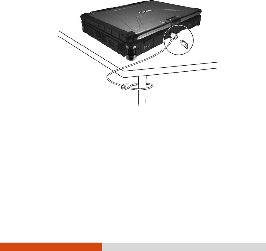
Caring for the Computer 8-3
Using the Cable Lock
You can use a Kensington-type cable lock to protect your computer
against theft. The cable lock is available in most computer stores.
To use the lock, loop the lock cable around a stationary object such as a
table. Insert the lock to the Kensington lock hole and turn the key to
secure the lock. Store the key in a safe place.

8-4 Caring for the Computer
Taking Care of the Computer
Location Guidelines
For optimal performance, use the computer where the
recommended temperature is between 0C (32F) and 55C (131F) –
actual operating temperature depending on product specifications.
Avoid placing the computer in a location subject to high humidity,
extreme temperatures, mechanical vibration, direct sunlight, or heavy
dust.
Do not cover or block any ventilation openings on the computer. For
example, do not place the computer on a bed, sofa, rug, or other
similar surface. Otherwise, overheating may occur that results in
damage to the computer.
Keep the computer at least 13 cm (5 inches) away from electrical
appliances that can generate a strong magnetic field such as a TV,
refrigerator, motor, or a large audio speaker.
Avoid moving the computer abruptly from a cold to a warm place. A
temperature difference of more than 10C (18F) may cause
condensation inside the unit, which may damage the storage media.
Do not place the computer on an unsteady surface.
General Guidelines
Do not place heavy objects on top of the computer when it is closed
as this may damage the display.
The screen surface is easily scratched. Do not use paper towels to
clean the display but use the included soft cloth. Avoid touching it
with your fingers, pen, or pencil.
To maximize the life of the backlight in the display, allow the backlight
to automatically turn off as a result of power management. Avoid

Caring for the Computer 8-5
using a screen saver or other software that prevents the power
management from working.
Cleaning Guidelines
Never clean the computer with its power on.
Use a soft cloth moistened with water or a non-alkaline detergent to
wipe the exterior of the computer.
Gently wipe the display with a soft, lint-free cloth. Do not use alcohol
or detergent on the display.
Dust or grease on the touchpad can affect its sensitivity. Clean the
pad by using adhesive tape to remove the dust and grease on its
surface.
Battery Pack Guidelines
Recharge the battery pack when it is nearly discharged. When
recharging, make sure that the battery pack is fully charged. Doing so
may avoid harm to the battery pack.
The battery pack is a consumable product and the following
conditions will shorten its life:
– when frequently charging the battery pack
– when using, charging, or storing the battery in high temperature
condition
To avoid hastening the deterioration of the battery pack thereby
prolonging its useful life, minimize the number of times you charge it so
as not to frequently increase its internal temperature.
Charge the battery pack between 10C ~ 30C (50F ~ 86F)
temperature range.
A higher environment temperature will cause the battery pack’s
temperature to rise. Avoid charging the battery pack inside a closed
vehicle and in hot weather condition.

8-6 Caring for the Computer
Also, charging will not start if the battery pack is not within the allowed
temperature range.
It is recommended that you do not charge the battery pack more
than once a day.
It is recommended that you charge the battery pack with the
computer’s power off.
To maintain the battery pack’s operating efficiency, store it in a cool
dark place removed from the computer and with 30% ~ 40% charge
remaining.
Important guidelines when using the battery pack.
When installing or removing the battery pack take note of the
following:
– avoid installing or removing the battery pack when the computer is
in Sleep mode. Abruptly removing the battery pack may cause loss
of data or the computer may become unstable.
– avoid touching the battery pack terminals or damage may occur,
thereby causing improper operation to it or the computer.
The computer’s input voltage and surrounding temperature will
directly affect the battery pack’s charge and discharge time:
– charging time will be prolonged when the computer is turned on.
To shorten the charging time, it is recommended that you place the
computer in sleep or hibernation mode.
– a low temperature will prolong the charging time as well as hasten
the discharge time.
Touchscreen Guidelines
Use the finger or the included touchscreen pen on the display. Using a
sharp or metallic object other than your finger or touchscreen pen
may cause scratches and damage the display, thereby causing
errors.
Avoid using excessive force that may cause damage to the display.

Caring for the Computer 8-7
Use a soft cloth to remove dirt on the display. The touchscreen surface
has a special protective coating that prevents dirt from sticking to it.
Not using a soft cloth may cause damage to the special protective
coating on the touchscreen surface.
To remove hard to remove dirt, blow some steam on the particular
area and gently wipe away using a soft cloth.
Turn off the computer power when cleaning the display. Cleaning the
display with the power on may cause improper operation.
Use the touchscreen within the intended area only. The display area
and touchscreen operating area is the same. Using it beyond the
allowed area may cause damage to the display and result in
improper operation.
Do not use excessive force on the display. Avoid moving the
computer while holding the display or twisting the display. Avoid
placing objects on top of the display as this may cause the glass to
break thereby damaging the display.
Using the touchscreen during low temperature (less than 5oC) may
cause a slower response time, this is normal. A normal response time
may be restored upon returning to room temperature.
When there is noticeable discrepancy in the operation of the
touchscreen function (wrong location on intended operation or
improper display resolution), calibrate the touchscreen using the
calibration utility called IdeaCom Calibration on Windows XP/Vista or
CalTouch on Windows 7.

8-8 Caring for the Computer
When Traveling
Before traveling with your computer, make a backup of your hard disk
data into flash disks or other storage devices. As an added
precaution, bring along an extra copy of your important data.
Make sure that the battery pack is fully charged.
Make sure that the computer is turned off and the top cover is
securely closed.
Do not leave objects in between the keyboard and closed display.
Disconnect the AC adapter from the computer and take it with you.
Use the AC adapter as the power source and as a battery-charger.
Hand-carry the computer. Do not check it in as luggage.
If you need to leave the computer in the car, put it in the trunk of the
car to avoid exposing the computer to excessive heat.
When going through airport security, it is recommended that you send
the computer and flash disks through the X-ray machine (the device
you set your bags on). Avoid the magnetic detector (the device you
walk through) or the magnetic wand (the handheld device used by
security personnel).
If you plan to travel abroad with your computer, consult your dealer
for the appropriate AC power cord for use in your country of
destination.

Troubleshooting 9-1
Chapter 9
Troubleshooting
Computer problems can be caused by hardware, software, or both.
When you encounter any problem, it might be a typical problem that can
easily be solved.
This chapter tells you what actions to take when solving common
computer problems.

9-2 Troubleshooting
Preliminary Checklist
Here are helpful hints to follow before you take further actions when you
encounter any problem:
Try to isolate which part of the computer is causing the problem.
Make sure that you turn on all peripheral devices before turning on the
computer.
If an external device has a problem, make sure that the cable
connections are correct and secure.
Make sure that the configuration information is properly set in the BIOS
Setup program.
Make sure that all the device drivers are correctly installed.
Make notes of your observations. Are there any messages on the
screen? Do any indicators light? Do you hear any beeps? Detailed
descriptions are useful to the service personnel when you need to
consult one for assistance.
If any problem persists after you follow the instructions in this chapter,
contact an authorized dealer for help.

Troubleshooting 9-3
Solving Common Problems
Battery Problems
The battery does not charge (Battery Charge indicator does not light yellow).
Make sure that the AC adapter is properly connected.
Make sure that the battery is not too hot or cold. Allow time for the
battery pack to return to room temperature.
Make sure that the battery pack is installed correctly.
Make sure that the battery terminals are clean.
The operating time of a fully charged battery becomes shorter.
If you often partially recharge and discharge, the battery might not be
charged to its full potential. Initialize the battery to solve the problem.
The battery operating time indicated by the battery meter does not match the
actual operating time.
The actual operating time can be different from the estimated time,
depending on how you are using the computer. If the actual
operating time is much less than the estimated time, initialize the
battery.
Bluetooth Problems
I cannot connect to another Bluetooth-enabled device.
Make sure that the Bluetooth card is correctly installed.
Make sure that the Bluetooth driver is correctly installed.
Make sure that both devices have activated Bluetooth.

9-4 Troubleshooting
Make sure that the distance between the two devices are not over 10
meters or that there are no walls or other obstructions between the
devices.
Make sure that the other device is not in “Hidden” mode.
Make sure that both devices are compatible.
Display Problems
Nothing appears on the screen.
During operation, the screen may automatically turn off as a result of
power management. Press any key to see if the screen comes back.
The brightness level might be too low. Increase brightness by pressing
the Fn+F7 hot key.
The display output might be set to an external device. To switch the
display back to the LCD, press the Fn+F5 hot key or change the display
through the settings in Display Properties.
The characters on the screen are dim.
Adjust the brightness and/or contrast.
Bad dots appear on the display at all times.
A small number of missing, discolored, or bright dots on the screen are
an intrinsic characteristic of TFT LCD technology. It is not regarded as a
LCD defect.
Resolution cannot be adjusted to desired setting.
Make sure that the VGA driver is installed correctly.
The external monitor displays nothing.
Make sure that the monitor is turned on.
Make sure that the monitor’s signal cable is properly connected.

Troubleshooting 9-5
Switch the display to the monitor by pressing the Fn+F5 hot key or
change the display through the settings in Display Properties.
Simultaneous display/multi-display does not work.
Make sure that you turn on the external monitor before turning on the
computer.
Press the Fn+F5 hot key to toggle through the display options or change
the settings in Display Properties in Windows.
Hardware Device Problems
The computer does not recognize a newly installed device.
The device may not be correctly configured in the BIOS Setup
program. Run the BIOS Setup program to identify the new type.
Make sure if any device driver needs to be installed. (Refer to the
documentation that came with the device.)
Make sure if the device needs any jumper or switch settings. (Refer to
the documentation that came with the device.)
Check the cables or power cords for correct connections.
For an external device that has its own power switch, make sure that
the power is turned on.
Hard Disk Drive Problems
The hard disk drive error message appears on the screen.
The hard disk drive has defects. Ask your dealer for help.
The hard disk drive operations seem slow.
The data files stored on the hard disk drive may be fragmented. Use a
tool such as Window’s Disk Defragmenter to defragment the files.
The hard disk drive in-use indicator glows without blinking.

9-6 Troubleshooting
The data files stored on the hard disk drive may be fragmented. Use a
tool such as Window’s Disk Defragmenter to defragment the files.
Keyboard, Mouse, and Touchpad Problems
The keyboard does not respond.
Try connecting an external keyboard. If it works, contact an
authorized dealer, as the internal keyboard cable might be loose.
Water or liquid is spilt into the keyboard.
Immediately turn off the computer and unplug the AC adapter. Then
turn the keyboard upside down to drain the liquid out of the keyboard.
Make sure to clean up any part of the spill you can get to. Though the
keyboard of your computer is spill-proof, liquid will remain in the
keyboard enclosure if you don’t remove it.
The numeric keypad is disabled.
Make sure that the Num Lock is switched on. (Check if the Num Lock
Indicator glows or not.)
The external keyboard does not work.
Make sure that the keyboard cable is properly connected.
The USB mouse does not work.
Make sure that the mouse cable is properly connected.
The touchpad does not work, or the pointer is difficult to control with the
touchpad.
Make sure that the touchpad is clean.
LAN Problems
I cannot access the network.
Make sure that the LAN driver is correctly installed.

Troubleshooting 9-7
Make sure that the LAN cable is properly connected to the RJ-45
connector and the network hub.
Make sure that the network configuration is appropriate.
Make sure that the user name or password is correct.
Modem Problems
The modem does not work.
Make sure that the modem driver is correctly installed.
Make sure that the telephone line is properly connected.
Make sure that the COM port in the communication software is
correctly set.
Turn off power management.
PC Card Problems
The PC card does not work.
Make sure that the PC card controller driver is correctly installed.
Make sure that the PC card is correctly seated.
If the card requires an IRQ (Interrupt ReQuest), make sure that there is
one available.
The PC card stops communicating properly.
The application may have been reset when the computer is turned off
or in Sleep/Standby mode. Exit and restart the application.
Power Management Problems
The computer does not enter Sleep/Standby or Hibernation mode
automatically.

9-8 Troubleshooting
If you have a connection to another computer, the computer does
not enter Sleep/Standby or Hibernation mode if the connection is
actively in use.
Make sure that the Sleep/Standby or Hibernation time-out is enabled.
The computer does not enter Sleep/Standby or Hibernation mode immediately.
If the computer is performing an operation, it normally waits for the
operation to finish.
The computer does not resume from Sleep/Standby or Hibernation mode.
The computer automatically enters Sleep/Standby or Hibernation
mode when the battery pack is empty. Do any one of the following:
Connect the AC adapter to the computer.
Replace the empty battery pack with a fully charged one.
The computer does not enter Hibernation mode with the Fn+F12 hot keys.
Make sure that the Hibernation function is specified for the sleep
button.
You might be using a PC card that prevents the computer from
entering Hibernation mode. To enter the mode, stop the
communication program and then remove the card or stop the card.
Software Problems
An application program does not work correctly.
Make sure that the software is correctly installed.
If an error message appears on the screen, consult the software
program’s documentation for further information.
If you are sure the operation has stop, reset the computer. (See
“Resetting the Computer” later in this chapter.)

Troubleshooting 9-9
Sound Problems
No sound is produced.
Make sure that the volume control is not set too low.
Make sure that the audio driver is correctly installed.
Make sure that the computer is not in Sleep/Standby mode.
If using an external speaker, make sure that the speaker is properly
connected.
Distorted sound is produced.
Make sure that the volume control is not set too high or too low. In
most cases, a high setting can cause the audio electronics to distort
the sound.
The sound system does not record.
Adjust the playback or recording sound levels.
The external microphone or audio device does not work.
Make sure that the microphone is connected to the proper connector
on the computer.
Make sure that your computer is equipped with the driver needed.
Click the speaker symbol on the taskbar and check the Windows
volume control.
Check the volume control of your computer.
Startup Problems
When you turn on the computer, it does not respond and the Power Indicator
does not light green.
If you are using an external AC power, make sure that the AC adapter
is correctly and securely connected. If so, make sure that the
electrical outlet works properly.

9-10 Troubleshooting
If you are using the battery power, make sure that the battery is not
discharged.
When you turn on the computer, it stops after POST.
Restart your computer.
WLAN Problems
I cannot use the WLAN feature.
Make sure that the mini PCI-E WLAN card is correctly installed.
Make sure that the necessary driver(s) is correctly installed.
Make sure that the WLAN feature is turned on.
Transmission quality is poor.
Your computer may be in an out-of-range situation. Move your
computer closer to the Access Point or another WLAN device it is
associated with.
Check if there is high interference around the environment and solve
the problem as described next.
Radio interference exists.
Move your computer away from the device causing the radio
interference such as microwave oven and large metal objects.
Plug your computer into an outlet on a different branch circuit from
that used by the affecting device.
Consult your dealer or an experienced radio technician for help.
I cannot connect to another WLAN device.
Make sure that the WLAN feature is turned on.
Make sure that the SSID setting is the same for every WLAN device in
the network.
Your computer is not recognizing changes. Restart the computer.

Troubleshooting 9-11
Make sure that the IP address or subnet mask setting is correct.
I cannot communicate with the computer in the network when Infrastructure
mode is configured.
Make sure that the Access Point your computer is associated with is
powered on and all the LEDs are working properly.
If the operating radio channel is in poor quality, change the Access
Point and all the wireless station(s) within the BSSID to another radio
channel.
Your computer may be in an out-of-range situation. Move your
computer closer to the Access Point it is associated with.
Make sure that your computer is configured with the same security
option (encryption) to the Access Point.
Use the Web Manager/Telnet of the Access Point to check whether it
is connected to the network.
Reconfigure and reset the Access Point.
I cannot access the network.
Make sure that the necessary driver(s) is correctly installed.
Make sure that the network configuration is appropriate.
Make sure that the user name or password is correct.
You have moved out of range of the network.
Turn off power management.
Other Problems
The date/time is incorrect.
Correct the date and time via the operating system or BIOS Setup
program.

9-12 Troubleshooting
After you have performed everything as described above and still
have the incorrect date and time every time you turn on the
computer, the RTC (Real-Time Clock) battery is at the end of its life.
Call an authorized dealer to replace the RTC battery.

Troubleshooting 9-13
Resetting the Computer
You may have to reset (reboot) your computer on some occasions when
an error occurs and the program you are using hangs up.
If the computer operation seems to hang up, first wait. It is possible that
the computer is processing data. Periodically check the hard disk drive
in-use indicator, if it flashes irregularly, the program may be accessing
data and preventing you from using the keyboard. If you are sure the
operation has stopped and you cannot use the “restart” function of the
operating system, reset the computer.
Reset the computer by any one of these methods:
Press Ctrl+Alt+Del on your built-in keyboard.
Press the Reset button on the front panel of your computer.
If the above action does not work, press and hold the power button
for more than 5 seconds to force the system to turn off. Then turn on
the power again.
CAUTION: Resetting will cause any unsaved data to be lost.

Specifications A-1
Appendix A
Specifications
NOTE: Specifications are subject to change without any prior notice.
Parts Specifications
Processor Intel® i7-620UM, 2.0GHz, Max. 2.8 GHz with Intel Turbo Boost
Technology
CPU
Cache 512K L2, 4MB L3
Memory RAM (system) Up to 8 GB, 240-pin × 2, DDR3 SO-DIMM
Chipset Intel® QM57
BIOS 8 MB EEPROM, system and VGA BIOS, G-sensor support,
Plug-and-Play, ACPI 2.0 capability, boot from SATA/LAN/USB
devices, light sensor for LCD panel and keyboard backlight
brightness control support, computrace
Panel 12.1-inch TFT LCD, resolution up to 1280×800 WXGA
Touchscreen function and/or Active Digitizer feature (option)
(with pen holder)
Sunlight-readable (option), brightness > 1200 nits after
touchscreen or glass
Night vision (option), brightness < 1.7 nits after touchscreen or
glass, meets MIL-STD-3009
Video controller Integrated in Intel® GMA HD, DirectX® 10 support, dual view,
LCD/CRT simultaneous display capability, ECO mode support
Video memory BIOS selectable, 128MB/256MB (default)/Max DVMT (OS
dynamic auto-adjust)
Display
Video out VGA
Features Azalia interface, left/right-channel analog output for line-out
connector
Speaker One built-in
Audio
Ports Two audio ports for Line-out (green) / Mic-in (red)

A-2 Specifications
Parts Specifications
Keyboard Standard keys with numeric pad keys, 12 function keys, special
Fn (Function) key and Windows keys
Membrane keyboard, optional LED backlit membrane or
rubber keyboard
Pointing device Glide touchpad with 2 buttons, capacitance-type
Hard disk drive SATA interface, 5400 rpm support, 9.5 mm height 2.5-inch
diameter
HDD heater for low temperature –20C, solid state disk (option)
PCMCIA Type II × 1 and ExpressCard/54/32
Type II × 1 and Smart Card Reader (option)
Card Reader (option) Secure Digital (SD), SDHC-support
I/O ports USB port (USB 2.0 support) x 2, eSATA/USB combo port (SATA II
support), serial port (RS-232), RJ-45 port, RJ-11 port
Wi-Fi
802.11a/b/g/n 2 internal (pass-through for external antenna – option)
Triple band support 2.3~2.7, 3.3~3.8, 5.1~5.8 GHz
WCDMA/HSDPA
2100 MHz (3.5G) 2 internal (pass-through for external antenna – option)
cannot co-exist with Wimax
Bluetooth 2.4G 1 internal
Antenna
GPS 1.5G 1 internal
Modem Azalia interface, 56 Kbps, ITU V.90 MDC 1.5 internal fax modem
LAN 10/100/1000 base-T Ethernet
Wireless LAN (option) Intel® Centrino Advanced-N6200 AGN
Bluetooth (option) Specification 2.1 module plus EDR
Camera 2.0 M pixel
GPS RS232 interface
3G EDGE/HSDPA/HSUPA/EVDO multi-band, with internal SIM slot
(mini-card)
Security Kensington lock
TPM 1.2
Smart Card Reader (option)
Fingerprint scanner (option)
Docking 100-pin, engage with vehicle docking
Handle Grip and cross-type hand strap
Power AC adapter Universal 60 W; input: 100240 V, 50/60 Hz; output: 19 V

Specifications A-3
Parts Specifications
Battery Li-ion smart 6-cell battery 5200 mAH / 11.1 V (option)
Li-ion smart 9-cell battery 7800 mAH / 11.1 V
user-swappable, under –20 oC combined with hard drive low
temperature solution
Accessories (option) Stylus for touchscreen, active digitizer pen, vehicle docking
(need to combine with docking connector)
Dimension (L×W×H) 314×227×49 mm (12.4×8.74×1.93 inch)
Weight 2.8 kg (5.95 lb)
Temperature Operating: 0 C (32 F) to 60 C (140 F)
–20 C (–4 F) to 71 C (160 F) – low temperature option
Non-operating: –40 C (–40 F) to 70 C (158 F)
Humidity 5 % to 95 % relative, non-condensing
Altitude Operating: 15,000 ft
Non-operating: 40,000 ft
Shock Operating: 15 g, 11 ms half-sine wave
Non-operating: 50 g, 11 ms half-sine wave
Vibration Random vibration:
Operating: MIL-STD-810F, 514.5C-1 – highway truck exposure
Non-operating: MIL-STD-810F, 514.5C-17
Drop 100 cm drop 26 times onto plywood plate surface
Enclosure IP65 (with input/output doors closed)
Environment
ESD Air discharge: 0~8 KV (included) no error; 9~15 KV allow soft
error
Contact discharge: 0~6 KV (included) no error; 7~8 KV allow
soft error
EMC FCC part 15, subpart B, class B, CE, CCC, BSMI Regulation
Safety UL, UL1604, TUV, TUV/CB, E-mark
RoHS 6 European union banned materials, EPEAT silver Green
Product
Coverage Other 12 universal GP product banned materials, ENERGY STAR,
WEEE

Regulatory Information B-1
Appendix B
Regulatory Information
This appendix provides regulatory statements and safety notices on your
computer.
NOTE: Marking labels located on the exterior of your computer indicate the
regulations that your model complies with. Please check the marking labels and
refer to the corresponding statements in this appendix. Some notices apply to
specific models only.

B-2 Regulatory Information
On the Use of the System
Class B Regulations
USA
Federal Communications Commission Radio Frequency Interference Statement
NOTE:
This equipment has been tested and found to comply with the limits for a
Class B digital device pursuant to Part 15 of the FCC Rules. These limits are
designed to provide reasonable protection against harmful interference
in a residential installation. This equipment generates, uses, and can
radiate radio frequency energy and, if not installed and used in
accordance with the instructions, may cause harmful interference to
radio communications. However, there is no guarantee that interference
will not occur in a particular installation. If this equipment does cause
harmful interference to radio or television reception, which can be
determined by turning the equipment off and on, the user is encouraged
to try to correct the interference by one or more of the following
measures:
Reorient or relocate the receiving antenna.
Increase the separation between the equipment and receiver.
Connect the equipment into an outlet on a circuit different from that
to which the receiver is connected.
Consult the dealer or an experienced radio/TV technician for help.
Any changes or modifications not expressly approved by the
manufacturer could void the user’s authority to operate the equipment.
Please note:
The use of a non-shielded interface cable with this equipment is
prohibited.

Regulatory Information B-3
Canada
Canadian Department of Communications
Radio Interference Regulations Class B Compliance Notice
This Class B digital apparatus meets all requirements of the Canada
Interference-Causing equipment regulations.
Cet appareil numérique de Classe B respecte toutes les exigences du
Règlement Canadien sur le matériel brouileur.
This digital apparatus does not exceed the Class B limits for radio noise
emissions from digital apparatus set out in the Radio Interference
Regulations of the Canadian Department of Communications.
Le présent appareil numérique n’émet pas de bruits radioélectriques
dépassant les limites applicables aux appareils numériques de la classe B
prescrites dans le Règlement sur le brouillage radioélectrique édicté par
le ministère des Communications du Canada.
UL1604 Installation Instructions
This equipment is suitable for use in Class I, Division 2, Groups A, B, C
and D OR non-hazardous locations only.
WARNING – EXPLOSION HAZARD – Do not disconnect equipment
unless power has been removed or the area is known to be
non-hazardous.
WARNING – EXPLOSION HAZARD - Substitution of components may
impair suitability for Class I, Division 2.
Non-LPS or TNV output connectors identify the type of circuit, intended
cable type or relevant circuit characteristics.
"IMPORTANT SAFETY INSTRUCTIONS - When using your telephone
equipment, basic safety precautions should always be followed to
reduce the risk of fire, electric shock and injury to persons, including
the following:
Do not use this product near water for example, near a bathtub,
washbowl, kitchen sink or laundry tub, in a wet basement or near a

B-4 Regulatory Information
swimming pool.
Avoid using a telephone (other than a cordless type) during an
electrical
storm. There may be a remote risk of electric shock from lightning.
Do not use the telephone to report a gas leak in the vicinity of the
leak.
Use only the power cord and batteries indicated in this manual. Do not
dispose of batteries in a fire. They may explode. Check with local
codes for possible special disposal instructions.
“SAVE THESE INSTRUCTIONS"
Safety Notices
About the Battery
Caution Texts Concerning Lithium Batteries
DANISH
ADVARSEL! Lithiumbatteri – Eksplosionsfare ved fejlagtig håndtering.
Udskiftning må kun ske med batteri af samme fabrikat og type. Levér det
brugte batteri tilbage til leverandøren.
NORWEGIAN
ADVARSEL: Eksplosjonsfare ved feilaktig skifte av batteri. Benytt samme
batteritype eller en tilsvarende type anbefalt av apparatfabrikanten.
Brukte batterier kasseres i henhold til fabrikantens instruksjoner.
SWEDISH
VARNING: Explosionsfara vid felaktigt batteribyte. Använd samma
batterityp eller en ekvivalent typ som rekommenderas av
apparattillverkaren. Kassera använt batteri enligt fabrikantens instruktion.
FINNISH
VAROITUS: Paristo voi räjähtää, jos se on virheellisesti asennettu. Vaihda
paristo ainoastaan valmistajan suosittelemaan tyyppiin. Hävitä käytetty
paristo valmistajan ohjeiden mukaisesti.

Regulatory Information B-5
ENGLISH
CAUTION: Danger of explosion if battery is incorrectly replaced. Replace
only with the same or equivalent type recommended by the equipment
manufacturer. Discard used batteries according to manufacturer's
instructions.
DEUTSCH
VORSICHT: Explosionsgefahr bei unsachgemäßem Austausch der Batterie.
Ersatz nur durch denselben oder einen vom Hersteller empfohlenen
gleich-wertigen Typ. Entsorgung gebrauchter Batterien nach Angaben
des Herstellers.
FRENCH
ATTENTION: II y a danger d’explosion s’il y a remplacement incorrect de la
batterie. Remplacer uniquement avec une batterie du même type ou
d’un type équivalent recommandé par le constructeur. Mettre au rebut
les batteries usagées conformément aux instructions du fabricant.
Attention (for USA Users)
The product that you have purchased contains a rechargeable battery.
The battery is recyclable. At the end of its useful life, under various state
and local laws, it may be illegal to dispose of this battery into the
municipal waste stream. Check with your local solid waste officials for
details in your area for recycling options or proper disposal.
About the AC Adapter
Use only the AC adapter supplied with your computer. Use of another
type of AC adapter will result in malfunction and/or danger.
Do not use the adapter in a high moisture environment. Never touch
the adapter when your hands or feet are wet.
Allow adequate ventilation around the adapter when using it to
operate the device or charge the battery. Do not cover the AC
adapter with paper or other objects that will reduce cooling. Do not
use the AC adapter while it is inside a carrying case.
Connect the adapter to a proper power source. The voltage
requirements are found on the product case and/or packaging.

B-6 Regulatory Information
Do not use the adapter if the cord becomes damaged.
Do not attempt to service the unit. There are no serviceable parts
inside. Replace the unit if it is damaged or exposed to excess moisture.
About the Modem
Caution
Never install telephone wiring during a lightning storm.
Never install telephone jacks in wet locations unless the jack is
specifically designed for wet locations.
Never touch non-insulated telephone wires or terminals unless the
telephone line has been disconnected at the network interface.
Use caution when installing or modifying telephone lines.
Avoid using the telephone function (other than a cordless type) during
an electrical storm. There may be a remote risk of electric shock from
lightning.
Do not use the telephone function to report a gas leak in the vicinity of
the leak.
Do not use this product near water, for example near a bathtub, wash
bowl, kitchen sink or laundry tub, in a wet basement or near a
swimming pool.
Caution (for USA Users)
To reduce the risk of fire, use only No.26 AWG or larger telecommunication
line cord.

Regulatory Information B-7
On the Use of the RF Device
NOTE: The information in this section applies to models with the wireless LAN
module.
USA and Canada Safety Requirements and Notices
Radio Frequency Interference Requirements and SAR
The FCC with its action in ET Docket 93-62 has adopted a safety standard
for human exposure to Radio Frequency (RF) electromagnetic energy
emitted by FCC certified equipment. The wireless LAN module meets the
Human Exposure limits found in OET Bulletin 65, 2001, and ANSI/IEEE C95.1,
1992. Proper operation of this radio according to the instructions found in
this manual will result in exposure substantially below the FCC’s
recommended limits. The following safety precautions should be
observed:
Do not touch or move antenna while the unit is transmitting or
receiving.
Do not hold any component containing the radio such that the
antenna is very close or touching any exposed parts of the body,
especially the face or eyes, while transmitting.
Do not operate the radio or attempt to transmit data unless the
antenna is connected; if not, the radio may be damaged.
Use in specific environments:
The use of wireless devices in hazardous locations is limited by the
constraints posed by the safety directors of such environments.
The use of wireless devices on airplanes is governed by the Federal
Aviation Administration (FAA).
The use of wireless devices in hospitals is restricted to the limits set forth
by each hospital.

B-8 Regulatory Information
Antenna use:
High-gain, wall-mount, or mast-mount antennas are designed to be
professionally installed and should be located at a minimum distance
of 30 cm (12 inches) or more from the body of all persons. Please
contact your professional installer, VAR, or antenna manufacturer for
proper installation requirements.
Explosive Device Proximity Warning
WARNING: Do not operate a portable transmitter (such as a wireless network
device) near unshielded blasting caps or in an explosive environment
unless the device has been modified to be qualified for such use.
Use on Aircraft Caution
CAUTION: Regulations of the FCC and FAA prohibit airborne operation of
radio-frequency wireless devices because their signals could interfere with
critical aircraft instruments.
EMC Requirements
This device uses, generates and radiates radio frequency energy. The
radio frequency energy produced by this device is well below the
maximum exposure allowed by the Federal Communications Commission
(FCC).
This device complies with the limits for a Class B digital device pursuant to
Part 15 subpart C of the FCC Rules and Regulations. Operation is subject
to the following two conditions:
(1) This device may not cause harmful interference.
(2) This device must accept any interference received, including
interference that may cause undesired operation.
The FCC limits are designed to provide reasonable protection against
harmful interference when the equipment is installed and used in
accordance with the instruction manual and operated in a commercial
environment. However, there is no guarantee that interference will not
occur in a particular commercial installation, or if operated in a residential
area.

Regulatory Information B-9
If harmful interference with radio or television reception occurs when the
device is turned on, the user must correct the situation at the user’s own
expense. The user is encouraged to try one or more of the following
corrective measures:
Reorient or relocate the receiving antenna.
Increase the separation between the equipment and receiver.
Connect the equipment into an outlet on a circuit different from that
to which the receiver is connected.
Consult the dealer or an experienced radio/TV technician for help.
CAUTION: The Part 15 radio device operates on a non-interference basis
with other devices operating at this frequency. Any changes or
modification to said product not expressly approved by the manufacturer
could void the user’s authority to operate this device.
Canada Radio Frequency Interference Requirements
To prevent radio interference to the licensed service, this device is
intended to be operated indoors and away from windows to provide
maximum shielding. Equipment (or its transmit antenna) that is installed
outdoors is subject to licensing.
Pour empêcher que cet appareil cause du brouillage au service faisant
l'objet d'une licence, il doit être utilisé à l'intérieur et devrait être placé loin
des fenêtres afin de fournir un écran de blindage maximal. Si le matériel
(ou son antenne d'émission) est installé à l'extérieur, il doit faire l'objet
d'une licence.

B-10 Regulatory Information
European Union CE Marking and Compliance
Notices
Statements of Compliance
English
This product follows the provisions of the European Directive 1999/5/EC.
Danish
Dette produkt er i overensstemmelse med det europæiske direktiv
1999/5/EC.
Dutch
Dit product is in navolging van de bepalingen van Europees Directief
1999/5/EC.
Finnish
Tämä tuote noudattaa EU-direktiivin 1999/5/EC määräyksiä.
French
Ce produit est conforme aux exigences de la Directive Européenne
1999/5/EC.
German
Dieses Produkt entspricht den Bestimmungen der Europäischen Richtlinie
1999/5/EC.
Greek
To προϊόν αυτό πληροί τις προβλέψεις της Ευρωπαϊκής Οδηγίας
1999/5/EC.
Icelandic
Þessi vara stenst reglugerð Evrópska Efnahags Bandalagsins númer
1999/5/EC.
Italian
Questo prodotto è conforme alla Direttiva Europea 1999/5/EC.

Regulatory Information B-11
Norwegian
Dette produktet er i henhold til bestemmelsene i det europeiske direktivet
1999/5/EC.
Portuguese
Este produto cumpre com as normas da Diretiva Européia 1999/5/EC.
Spanish
Este producto cumple con las normas del Directivo Europeo 1999/5/EC.
Swedish
Denna produkt har tillverkats i enlighet med EG-direktiv 1999/5/EC.
Local Restrictions of 802.11a/g/n Radio Usage
CAUTION: Due to the fact that the frequencies used by 802.11a/g/n wireless
LAN devices may not yet be harmonized in all countries, 802.11a/g/n
products are designed for use only in specific countries or regions, and is
not allowed to be operated in countries or regions other than those of
designated use. As a user of these products, you are responsible for
ensuring that the products are used only in the countries or regions for
which they were intended and for verifying that they are configured with
the correct selection of frequency and channel for the country or region
of use. Any deviation from permissible settings and restrictions in the
country or region of use could be an infringement of local law and may
be punished as such.
The European variant is intended for use throughout the European
Economic Area. However, authorization for use is further restricted in
particular countries or regions within countries, as follows:
General
European standards dictate maximum radiated transmit power of
100 mW Effective Isotropic Radiated Power (EIRP) and the frequency
range 2400 – 2483.5 MHz.
Belgium and the Netherlands
B-12 Regulatory Information
In Belgium and the Netherlands, the product may not be used outdoors.
See the instructions next under the heading “Turning Off the Wireless LAN
Radio.”
France
Departments in Which the Wireless LAN Module Can Be Used (Indoors Only)
The wireless LAN module can currently be used indoors only in the
following 38 departments of mainland France. Please turn off your wireless
LAN radio when operating the device in areas/places other than the 38
departments listed:
01 Ain Orientales 36
Indre 66
Pyrénées
02 Aisne 37
Indre et Loire 67
Bas Rhin
03 Allier 41
Loir et Cher 68
Haut Rhin
05 Hautes Alpes 42
Loire 70
Haute Saône
08 Ardennes 45
Loiret 71
Saône et Loire
09 Ariège 50
Manche 75
Paris
11 Aude 55
Meuse 82
Tarn et Garonne
12 Aveyron 58
Nièvre 84
Vaucluse
16 Charente 59
Nord 88
Vosges
24 Dordogne 60
Oise 89
Yonne
25 Doubs 61
Orne 90
Territoire de Belfort
26 Drôme 63
Puy du Dôme 94
Val de Marne
32 Gers 64
Pyrénées
Atlantique
Departments in Which the Wireless LAN Module’s Maximum EIRP Not
Shown in the Previous Table
Frequency Ranges
(MHz) Indoors Outdoors
2400 – 2446.5 10 mW Not permitted
2446.5 – 2483.5 100 mW 100 mW on private property with

Regulatory Information B-13
Ministry of Defense approval
Turning Off the Wireless LAN Radio
NOTE: Turning the wireless LAN radio off is not the same as disabling the
wireless LAN card. It is not necessary to disable the card to meet the
regulatory requirements.
While operating the computer in those French departments that do not
allow use of the wireless LAN equipment, the user of the equipment must
turn off the wireless LAN radio in order to comply with local regulations.