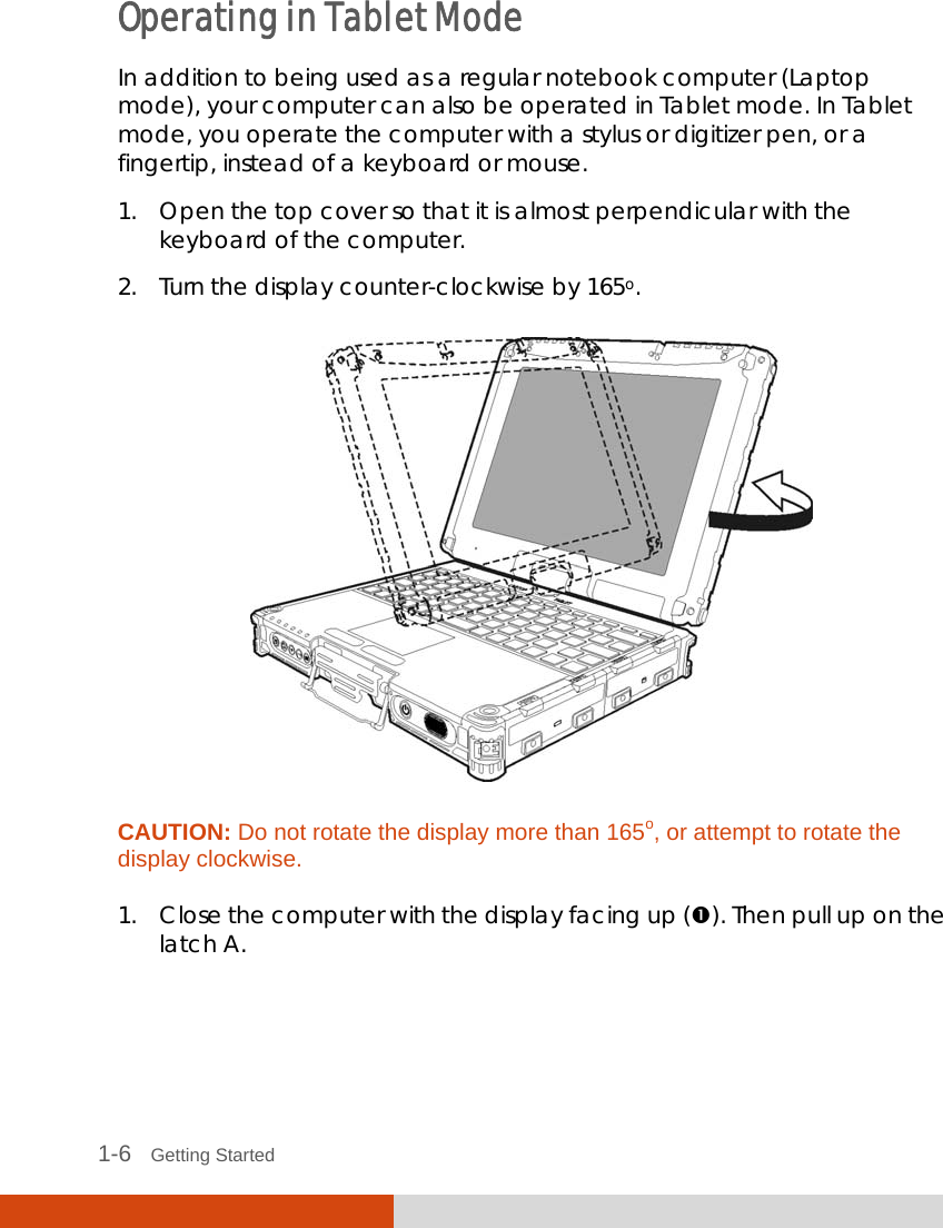
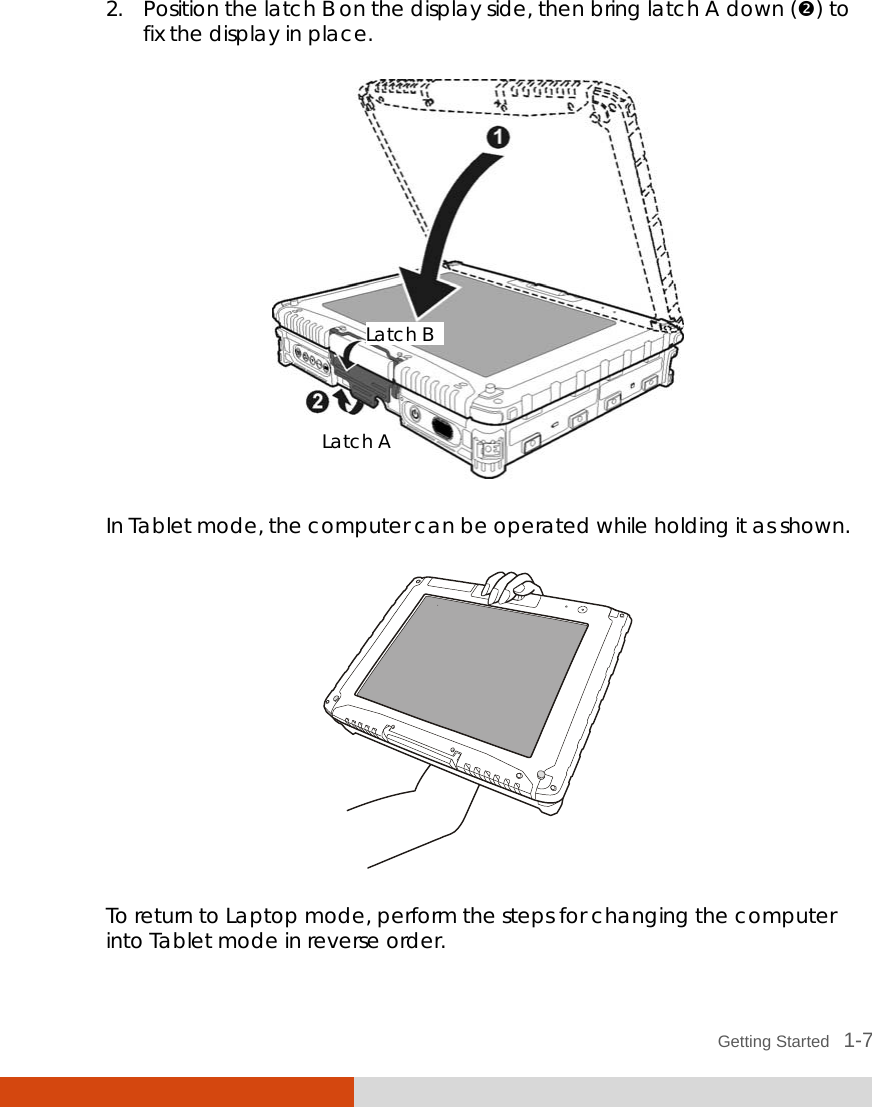
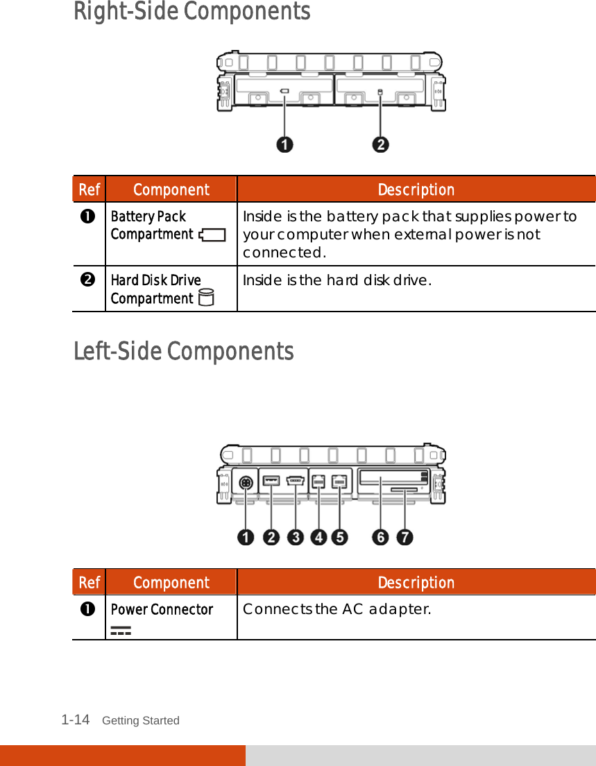
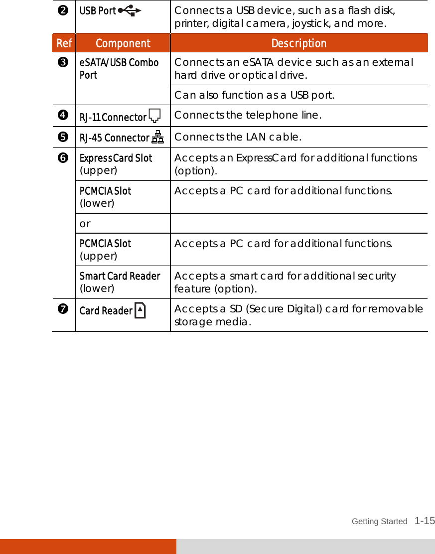
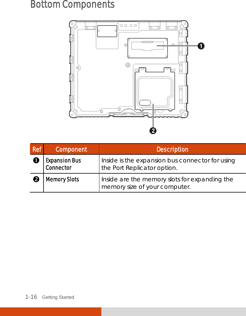
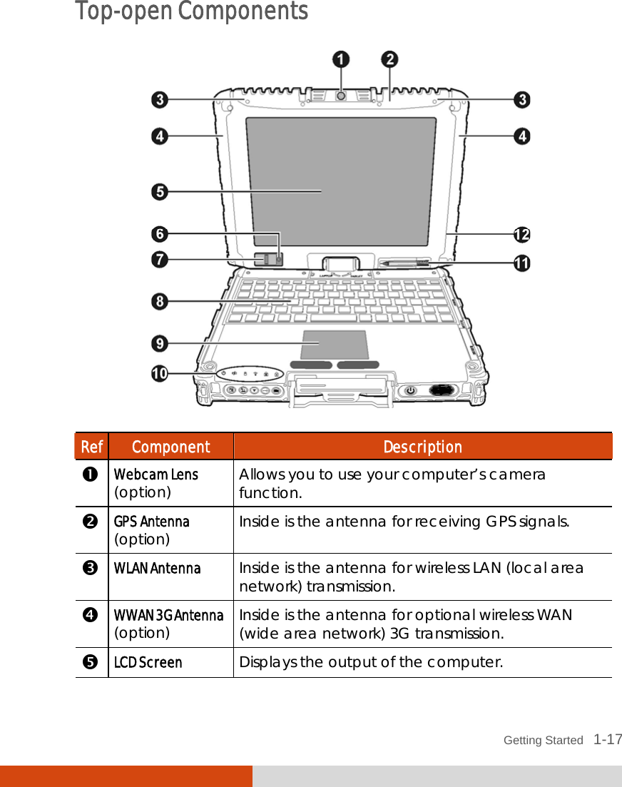
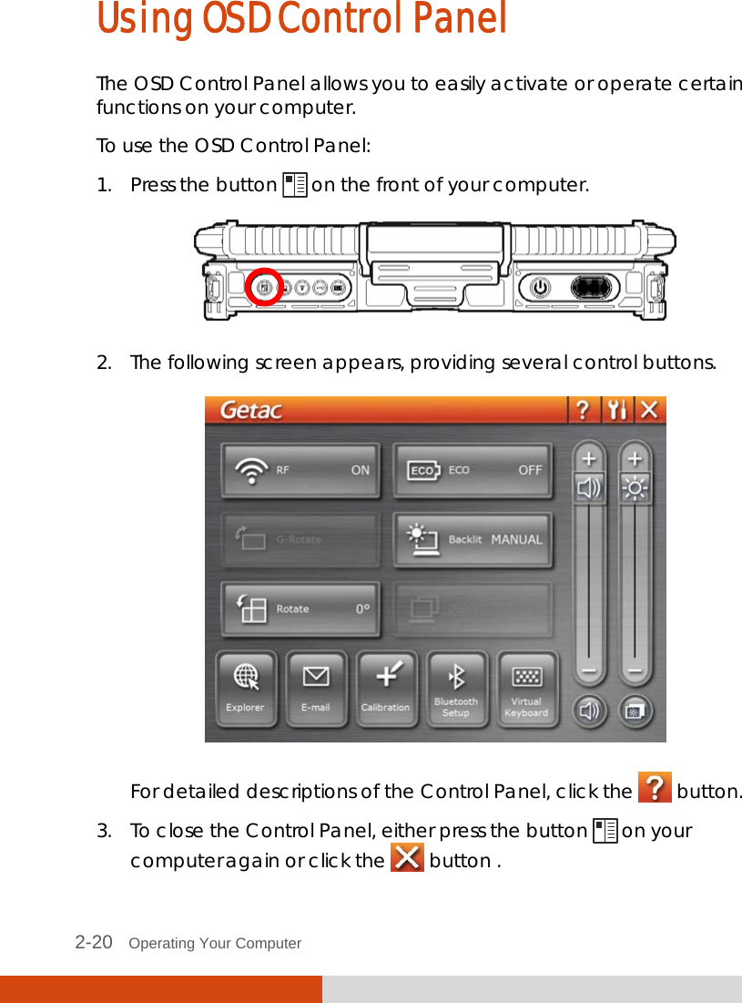
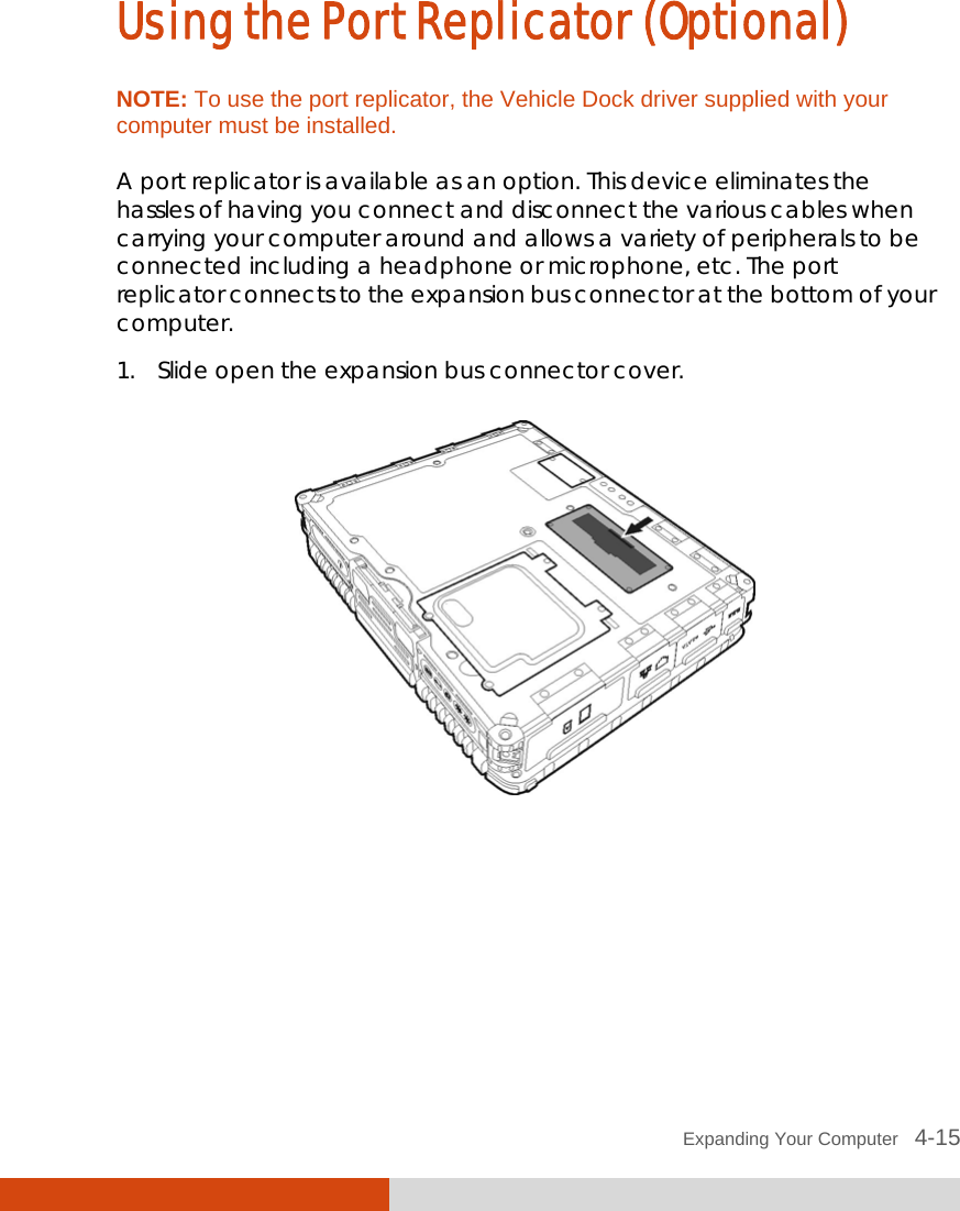
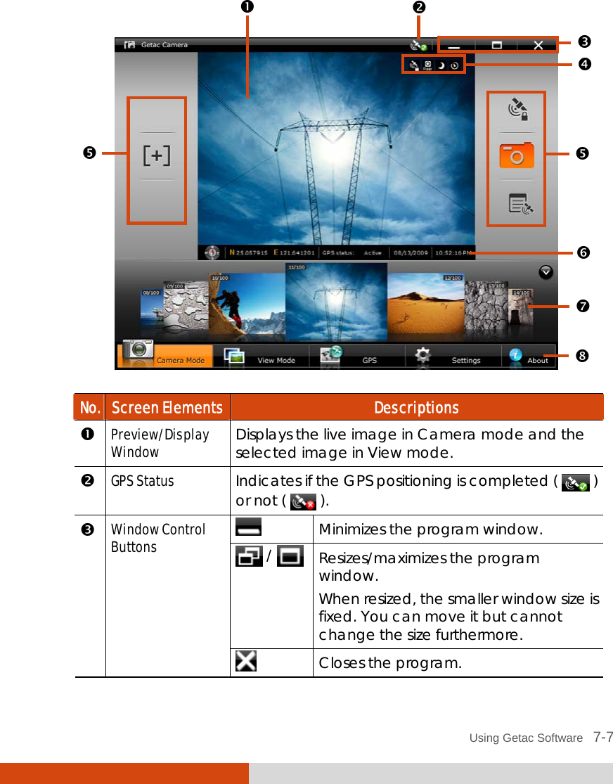
Getac Technology 043 NOTEBOOK COMPUTER User Manual V100 MAU043 English Manual
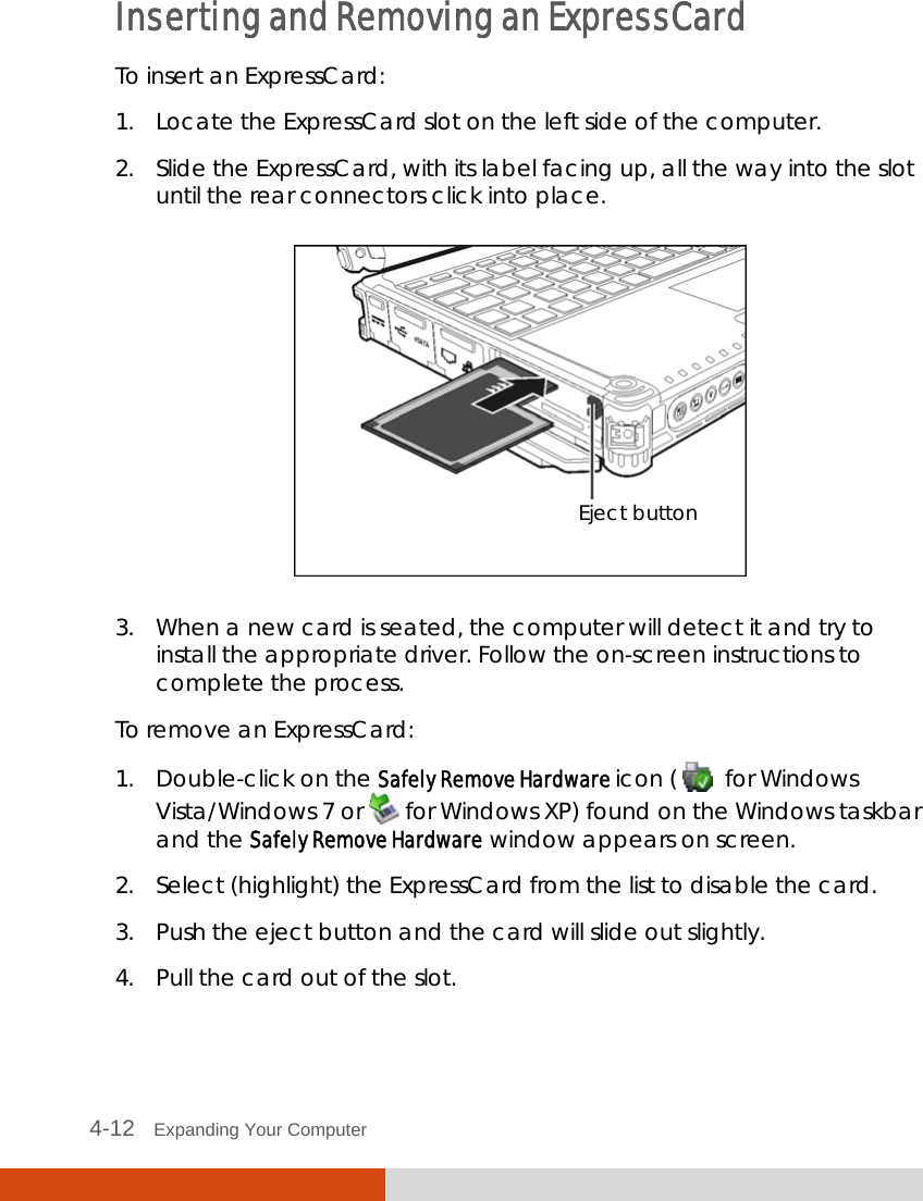
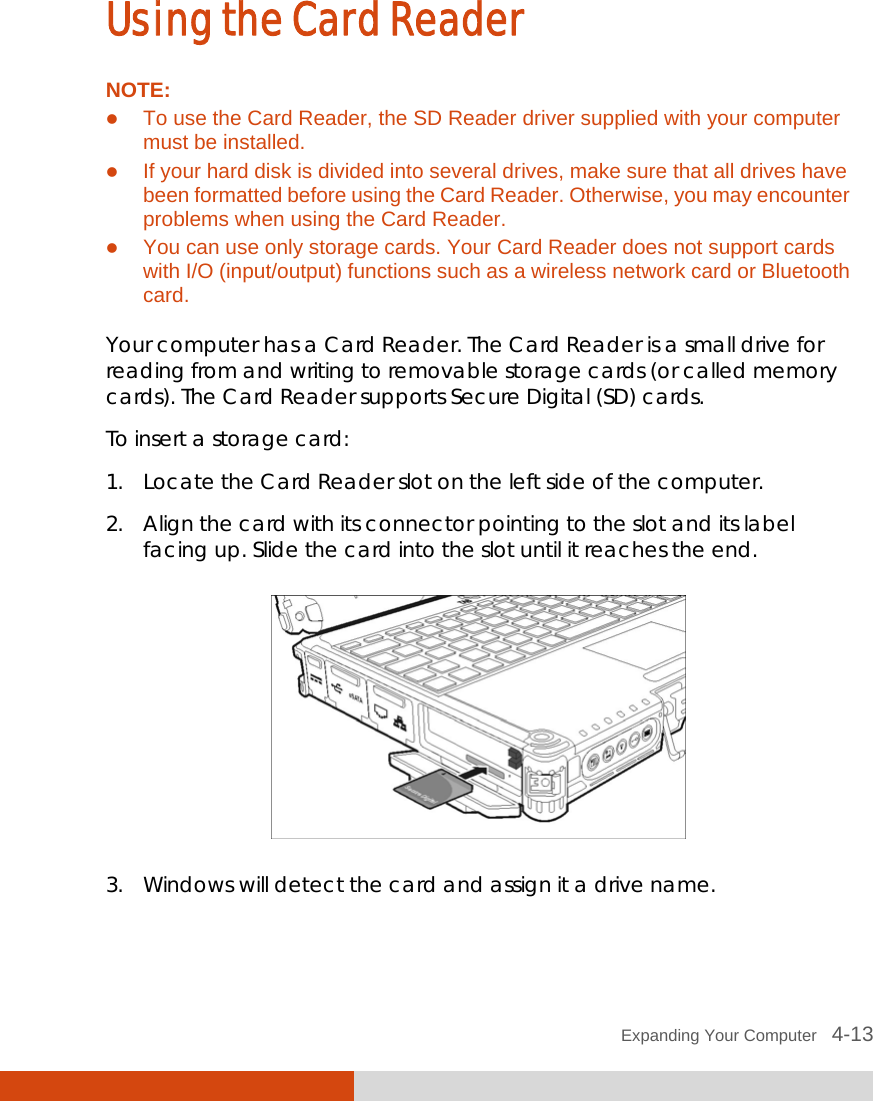
Getac Technology Corp. NOTEBOOK COMPUTER V100 MAU043 English Manual
UserManual.wiki
>
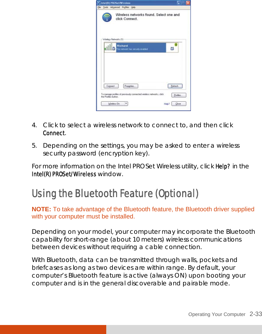
Getac Technology
>
043 User Manual
User Manual
Navigation menu
Upload a User Manual
Namespaces
Wiki Guide
HTML
PDF
Info
Views
User Manual
Discussion / Help
Navigation


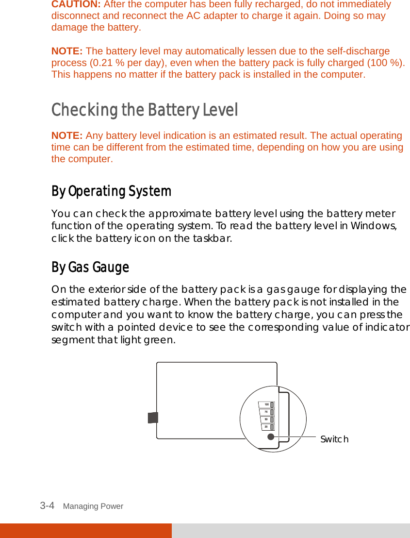


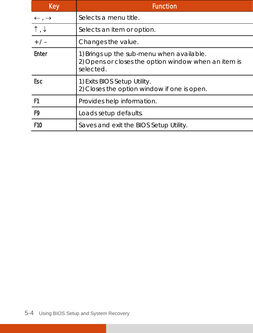
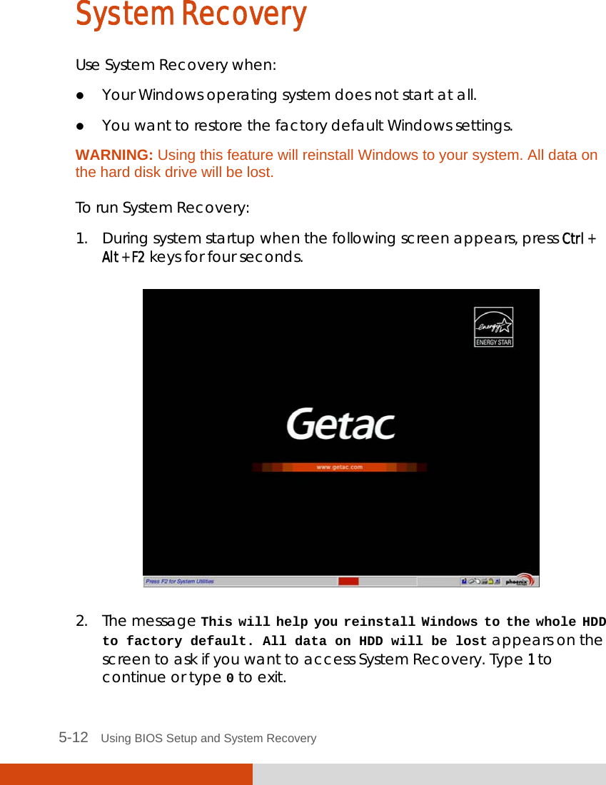
![Using BIOS Setup and System Recovery 5-3 Main Advanced Security Boot Exit Model: SATA HDD: System Time: System Date: Processor Info: Installed System Memory: System BIOS Version: KBC/EC BIOS Version: LAN MAC Address: Serial Number: V100 [INTEL SSDSA2M080G2GC] 80026MB [16:33:08] [06/10/2010] Intel(R)Core(TM)i7 CPU U640@1.20GHz 4096 MB R1.01 R1.01e 00-22-20-0A-74-F9 RA539V0013 F1 Help ↑↓ Select Item -/+ Change Values F9 Setup Defaults Esc Exit ←→ Select Menu Enter Select Sub-Menu F10 Save and Exit The BIOS Setup Utility screen can be divided into four areas: On the top is the menu bar containing the titles of the available menus. Each menu title brings a specific menu. The left column of the menu displays the menu items. The right column of the menu provides more detailed information when a menu item is highlighted. The bottom of the menu provides keyboard instructions for moving around and making selections. Moving Around and Making Selections You must go through two or three levels to complete the setting for an item. In most cases, there are two levels: menu title and submenu. Use the keyboard to move around and make selections. Keyboard information can be found at the bottom of the screen. A brief description of keyboard usage is listed next: 16](https://usermanual.wiki/Getac-Technology/043/User-Guide-1373021-Page-99.png)
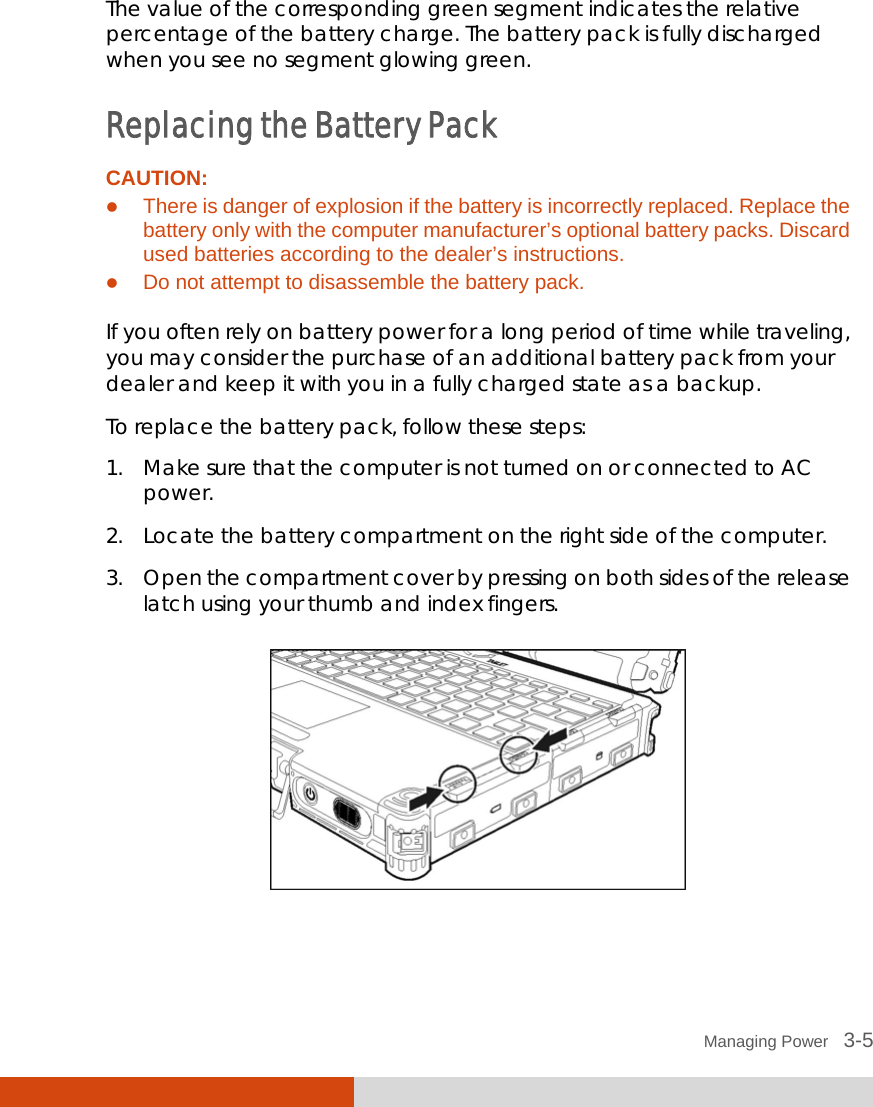
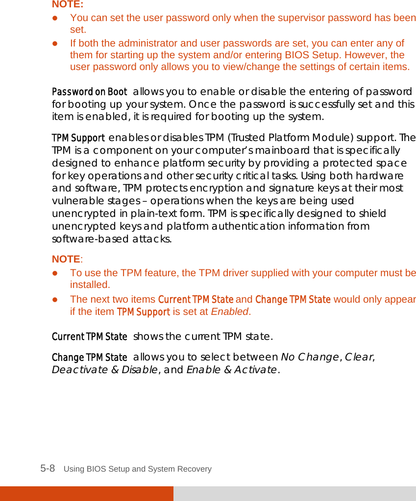
![Using BIOS Setup and System Recovery 5-5 Main Menu The Main menu contains the system date and time settings as well as shows the basic configuration of the system. Main Advanced Security Boot Exit Model: SATA HDD: System Time: System Date: Processor Info: Installed System Memory: System BIOS Version: KBC/EC BIOS Version: LAN MAC Address: Serial Number: V100 [INTEL SSDSA2M080G2GC] 80026MB [16:33:08] [06/10/2010] Intel(R)Core(TM)i7 CPU U640@1.20GHz 4096 MB R1.01 R1.01e 00-22-20-0A-74-F9 RA539V0013 F1 Help ↑↓ Select Item -/+ Change Values F9 Setup Defaults Esc Exit ←→ Select Menu Enter Select Sub-Menu F10 Save and Exit System Time sets the system time. System Date sets the system date. 16](https://usermanual.wiki/Getac-Technology/043/User-Guide-1373021-Page-101.png)
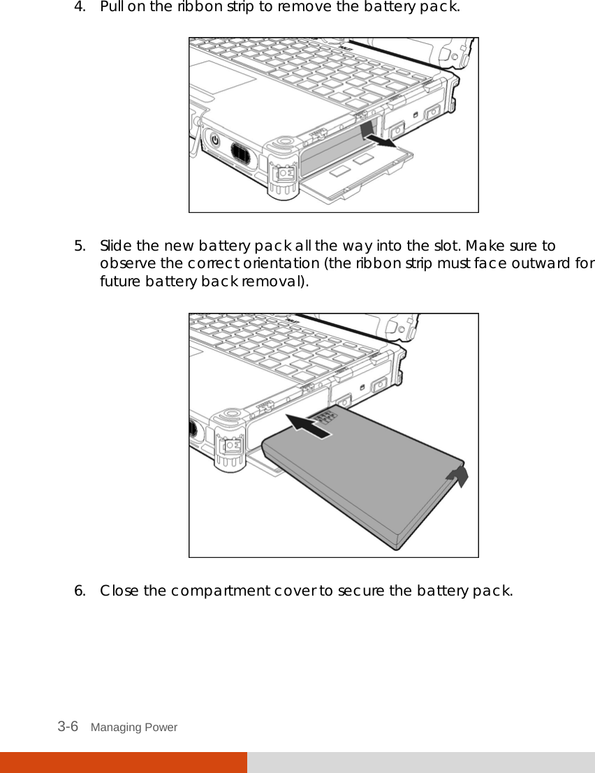
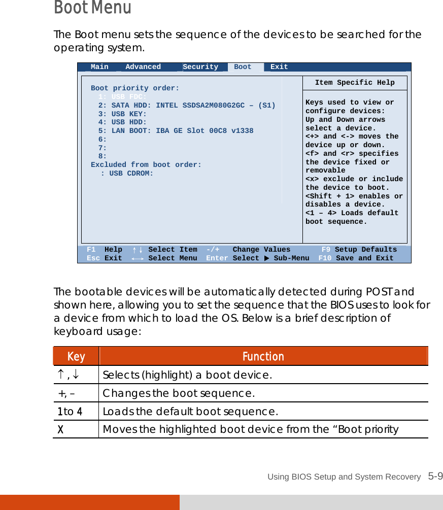
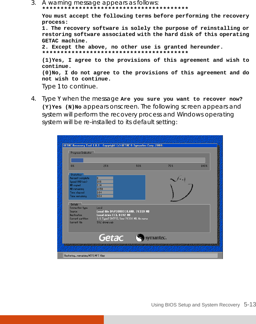
![5-6 Using BIOS Setup and System Recovery Advanced Menu The Advanced menu contains the advanced settings as shown next. Main Advanced Security Boot Exit Item Specific Help Japanese Keyboard: SATA Mode Total Graphics Memory: Serial port COM1: Serial port COM2: Serial port COM3: Serial port COM4: Boot-time Diagnostic Screen: Wake-On-LAN(WOL) Turbo Mode Intel Trusted Execution Intel AMT Setup Prompt: [Disabled] [AHCI] [MaxDVMT] [Enabled] [Enabled] [Enabled] [Enabled] [Disabled] [Disabled] [Enabled] [Disabled] [Enabled] ForceEntry F1 Help ↑↓ Select Item -/+ Change Values F9 Setup Defaults Esc Exit ←→ Select Menu Enter Select Sub-Menu F10 Save and Exit Japanese Keyboard enables support for the Japanese keyboard. SATA Mode sets the mode to enhanced AHCI (Advanced Host Controller Interface) or IDE. Turbo memory feature works only when the SATA AHCI mode is enabled. Total Graphics Memory sets the amount of total graphics memory (pre-allocated + fixed + DVMT) for use by the internal graphics device. Serial Port COM1/COM2/COM3/COM4 allows you to unconditionally disable it when set at Disabled. Boot-time Diagnostic Screen allows you to display the diagnostic screen during system boot-up. Wake-On-LAN (WOL) allow a LAN activity to wake up the system from S3 (Sleep) state. Disabled](https://usermanual.wiki/Getac-Technology/043/User-Guide-1373021-Page-102.png)
![Using BIOS Setup and System Recovery 5-7 Turbo Mode sets if turbo memory is enabled. Intel Trusted Execution enables utilization of additional hardware capabilities provided by Intel® Trusted Execution Technology. Intel AMT Setup Prompt sets if the prompt for entering Intel AMT Setup appears during POST. If disabled, you cannot enter Intel AMT Setup. Security Menu The Security menu contains the security settings, which safeguard your system against unauthorized use. Main Advanced Security Boot Exit Item Specific Help Supervisor Password Is: User Password Is: Set Supervisor Password:Set User Password Password on boot: TPM Support Current TPM State Change TPM State Set Clear [Enter] [Enter] [Disabled] [Eabled] UNKNOWN [Enable & Activated] Supervisor Password controls access to the setup utility. F1 Help ↑↓ Select Item -/+ Change Values F9 Setup Defaults Esc Exit ←→ Select Menu Enter Select Sub-Menu F10 Save and Exit Supervisor/User Password Is shows whether you have set the supervisor/user password or not for the system. Set Supervisor/User Password sets the supervisor/user password. When typing the password, first make sure that Num Lock is off, and then type the password in the entry fields and press Enter. Confirm your password by typing it again and pressing Enter. You can set the supervisor/user password to be required for starting up the system and/or entering BIOS Setup. Enter](https://usermanual.wiki/Getac-Technology/043/User-Guide-1373021-Page-103.png)


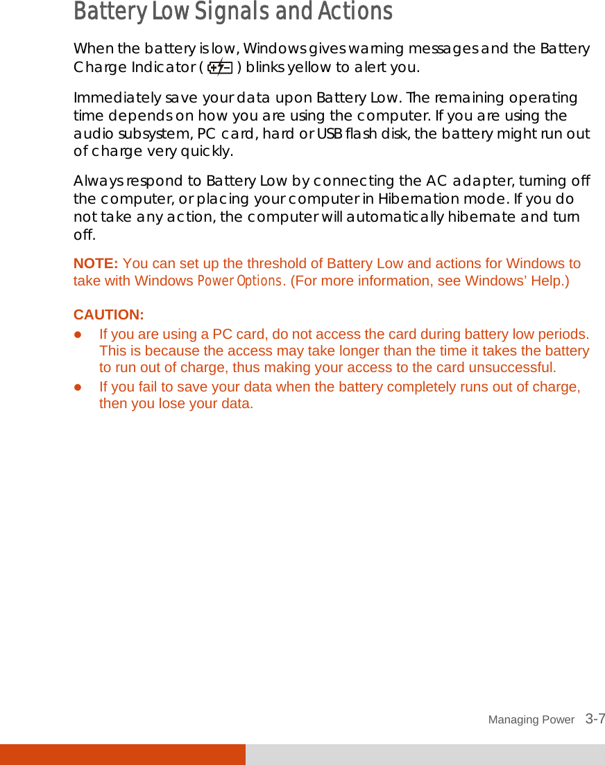
![Using Getac Software 7-19 Setting Items Name Descriptions Folder Path Sets the storage location of the images. To change to a different folder, tap Browse and select the folder. The default location is User\[user name]\Pictures folder that contains the original images. A subfolder named Thumbs contains a copy of the same images (with filename prefix Thumb_) for the thumbnail view. NOTE: If you are adding or deleting images using File Explorer, make sure to work on both the correct folder and its Thumbs subfolder. Displays the time throughout the program according to one of the two choices: System time zone (default) The time zone setting of the computer is taken into consideration. If the current location is in daylight saving time, the time will be adjusted accordingly. Time Option UTC The time is based on Coordinated Universal Time. Filename Prefix The default filename prefix is IMG. The complete filename is IMG_xxxxxx.jpg (where xxxxxx = sequential number). When the sequential number has reached 999999 and you are taking the next picture, a message will pop up to ask you to change the prefix. You can change the prefix by typing the characters (limited to A~Z, a~z, 0~9, - and _) in the entry field. Maximum number of characters allowed is 10.](https://usermanual.wiki/Getac-Technology/043/User-Guide-1373021-Page-145.png)