Getac Technology 047 WWAN Module User Manual rev02
Getac Technology Corp. WWAN Module rev02
UserManual.wiki
>
Getac Technology
>
047 User Manual
User Manual (rev02)
Navigation menu
Upload a User Manual
Namespaces
Wiki Guide
HTML
PDF
Info
Views
User Manual
Discussion / Help
Navigation
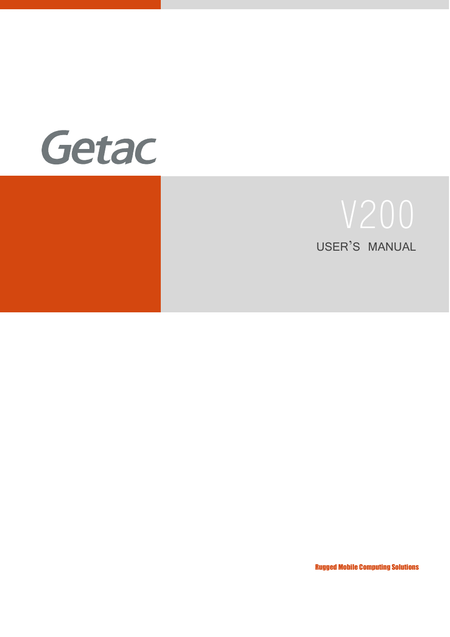


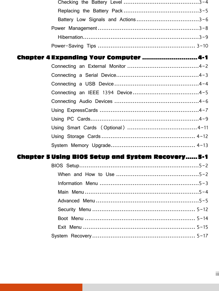


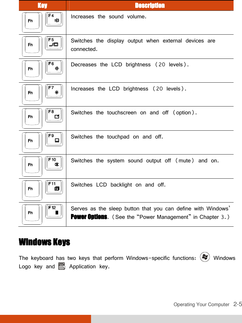
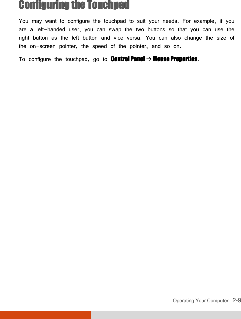


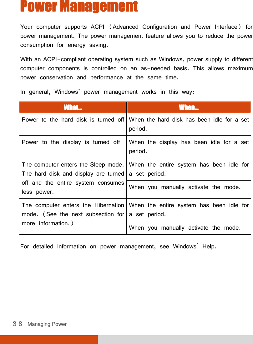


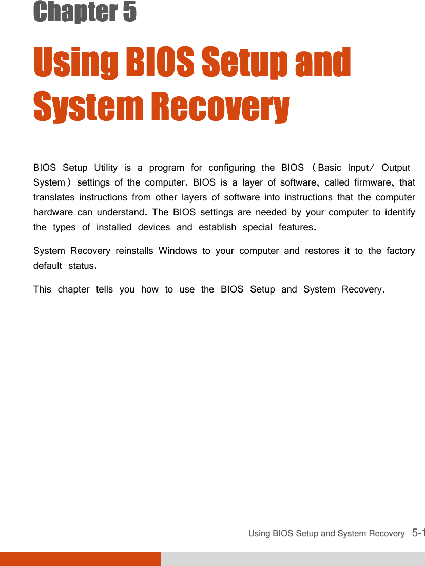
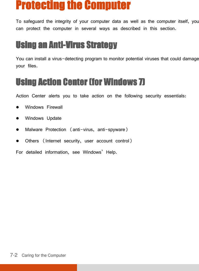
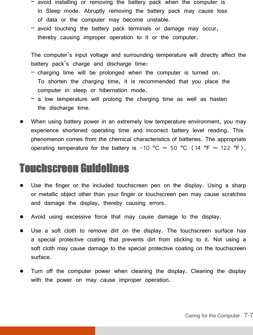
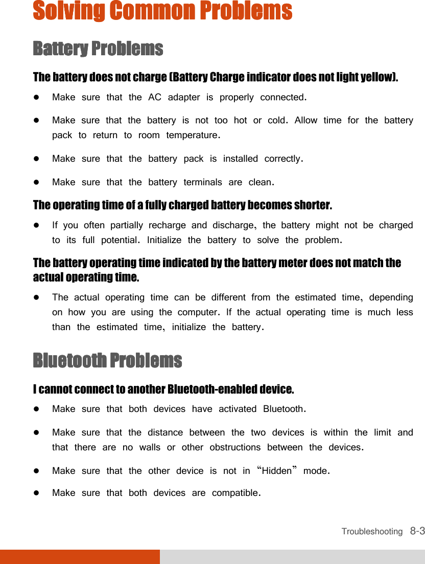
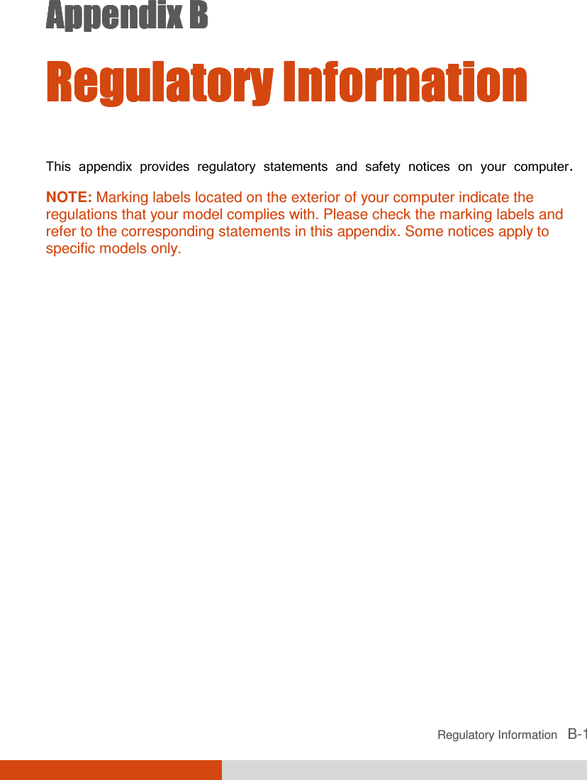
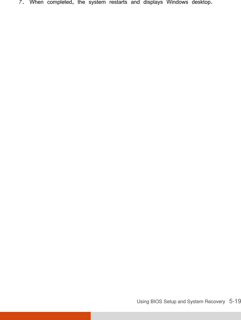
![5-4 Using BIOS Setup and System Recovery Main MenuMain MenuMain MenuMain Menu The Main menu contains various system settings. Information Main Advanced Security Boot Exit System Date: System Time: Legacy USB Support: [05/28/2012] [11:33:08] [Enabled] Item Specific Help View or set system date. F1 Help ↑↓↑↓↑↓↑↓ Select Item +/- Change Values F9 Setup Defaults Esc Exit ←→←→←→←→ Select Menu Enter Select Sub-Menu F10 Save and Exit System TimeSystem TimeSystem TimeSystem Time sets the system time. System DateSystem DateSystem DateSystem Date sets the system date. Legacy USB SupportLegacy USB SupportLegacy USB SupportLegacy USB Support enables or disables the system’s support for Legacy USB device in DOS mode. 05](https://usermanual.wiki/Getac-Technology/047/User-Guide-1776980-Page-88.png)
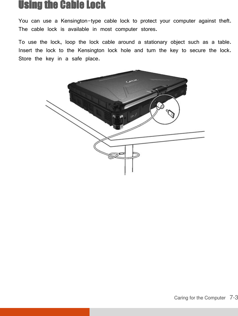
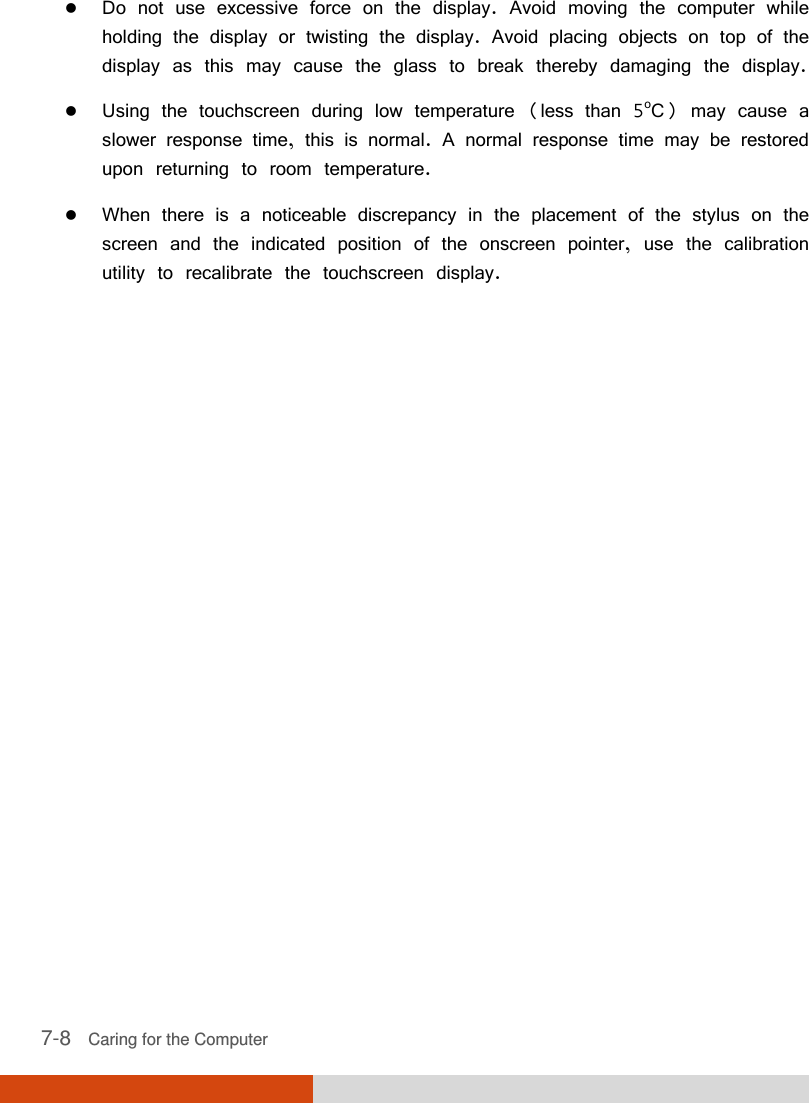
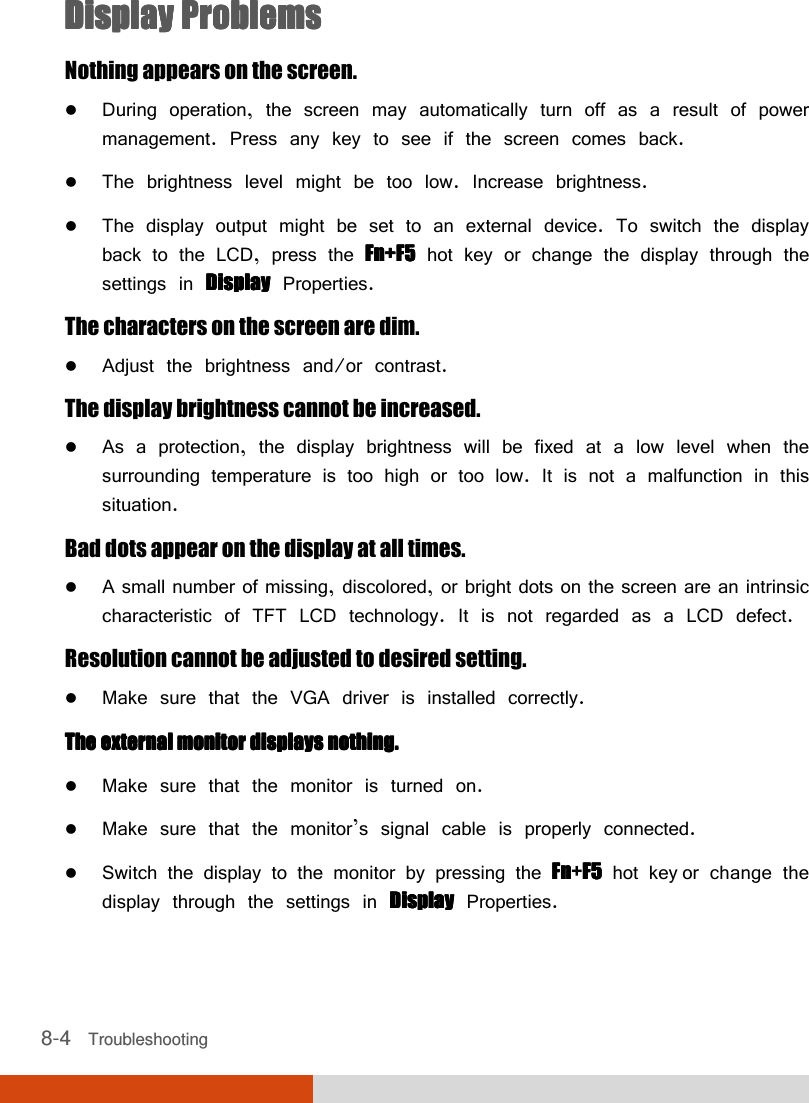
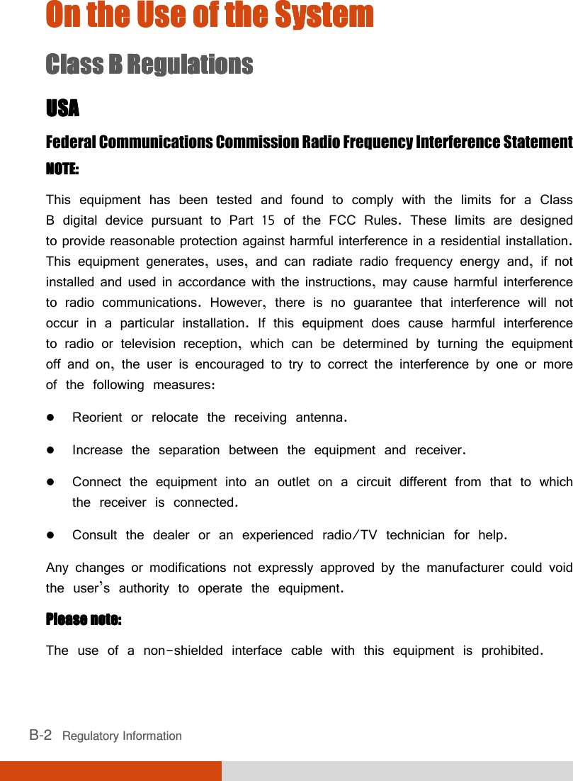
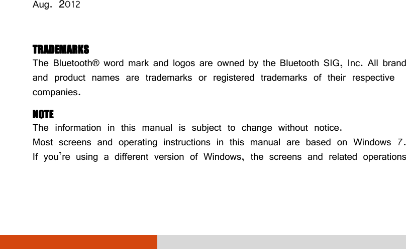
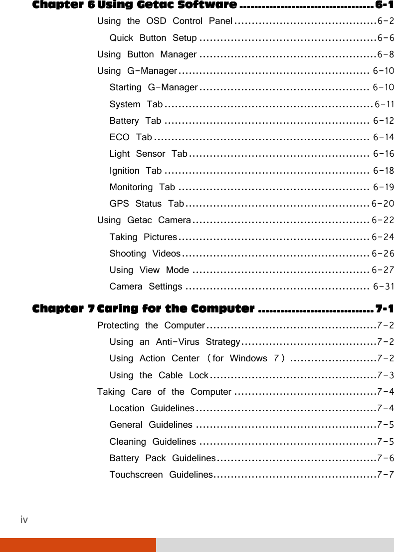
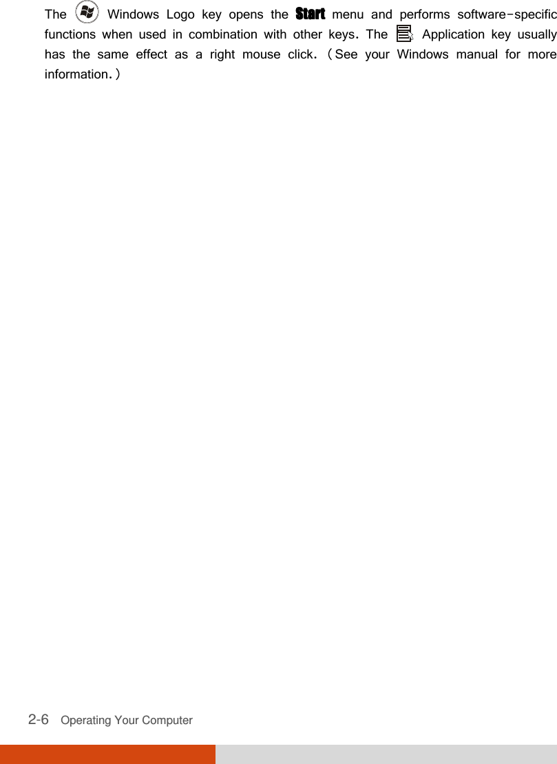
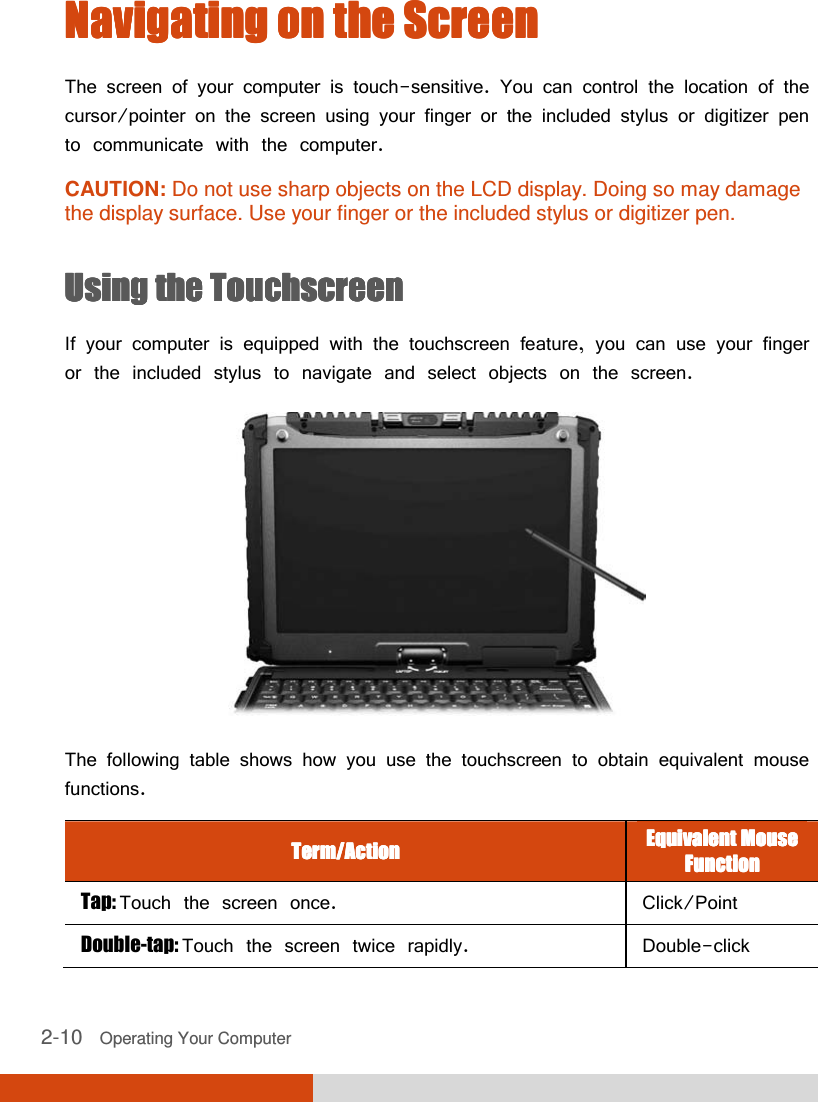
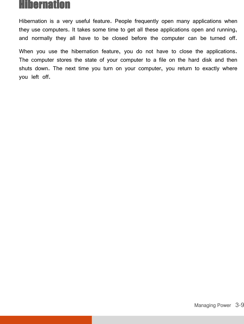
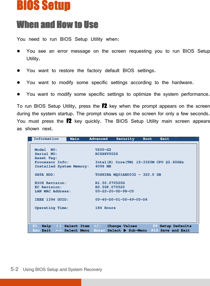
![Using BIOS Setup and System Recovery 5-5 Advanced MenuAdvanced MenuAdvanced MenuAdvanced Menu The Advanced menu contains the advanced settings as shown next. Information Main Advanced Security Boot Exit Intel (R) Rapid Start Technology Wake Up Capability System Policy AC Initiation: SATA Mode: AMT Configuration Virtualization Technology Setup Graphic Setup Device Configuration Serial COM Port Configuration [Performance] [Disabled] [AHCI] Item Specific Help iRST – Intel (R) Rapid Start Technology Configuration F1 Help ↑↓↑↓↑↓↑↓ Select Item +/- Change Values F9 Setup Defaults Esc Exit ←→←→←→←→ Select Menu Enter Select Sub-Menu F10 Save and Exit Intel (R) Rapid Start Technology Intel (R) Rapid Start Technology Intel (R) Rapid Start Technology Intel (R) Rapid Start Technology configures iRST. Press Enter Enter Enter Enter to access the submenu as shown below. Advanced Intel (R) Rapid Start Technology Item Specific Help iRST Support: [Disabled ] Enable iRST. F1 Help ↑↓↑↓↑↓↑↓ Select Item +/- Change Values F9 Setup Defaults Esc Exit ←→←→←→←→ Select Menu Enter Select Sub-Menu F10 Save and Exit Disabled](https://usermanual.wiki/Getac-Technology/047/User-Guide-1776980-Page-89.png)
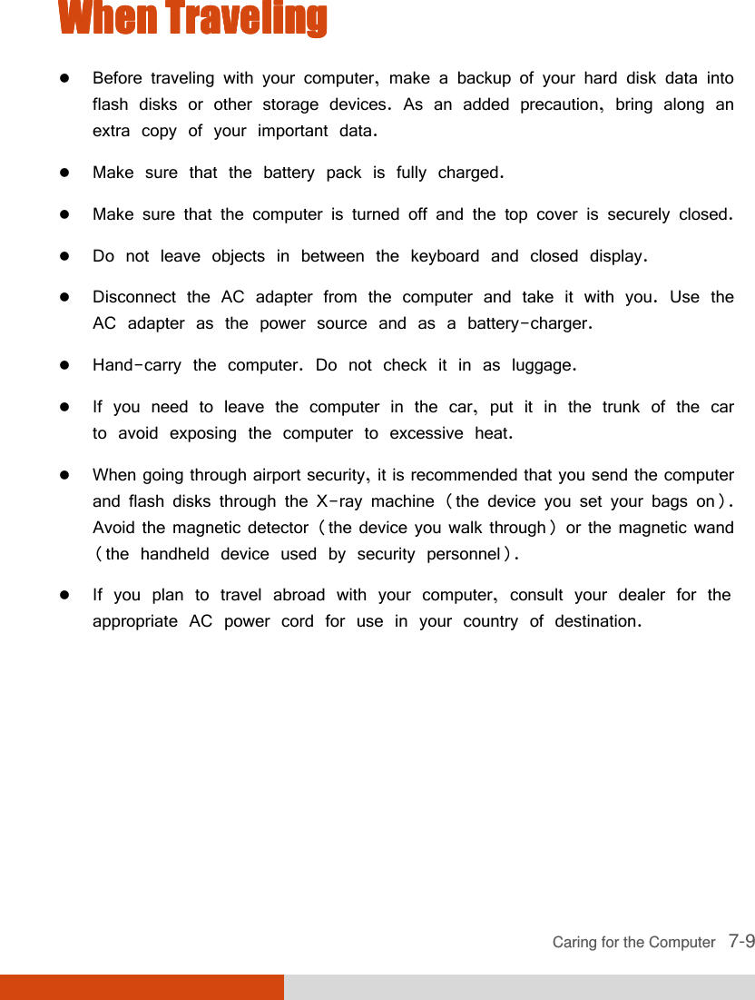
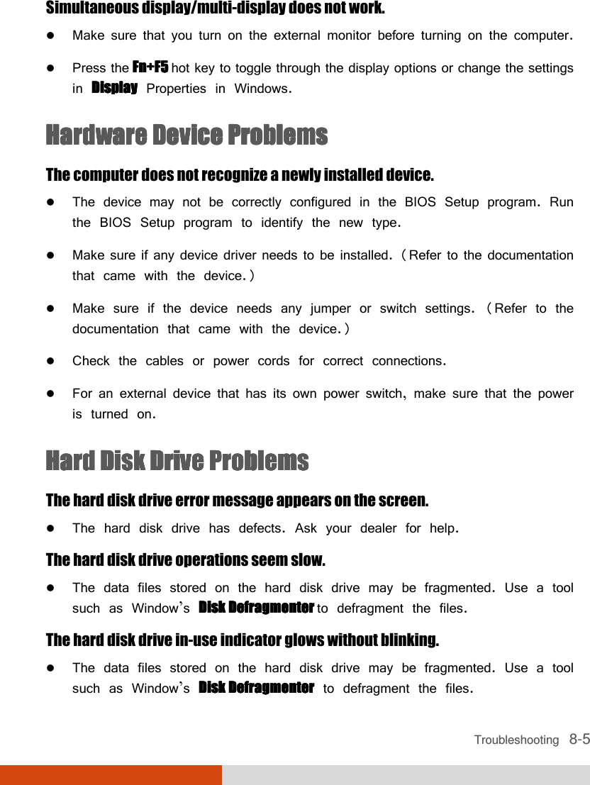
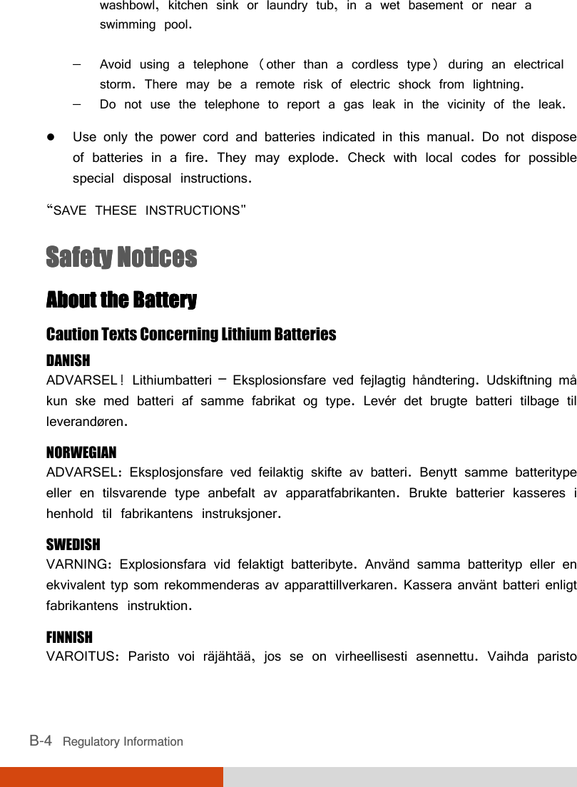
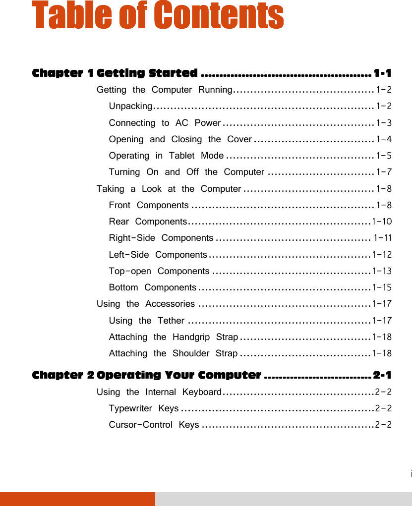
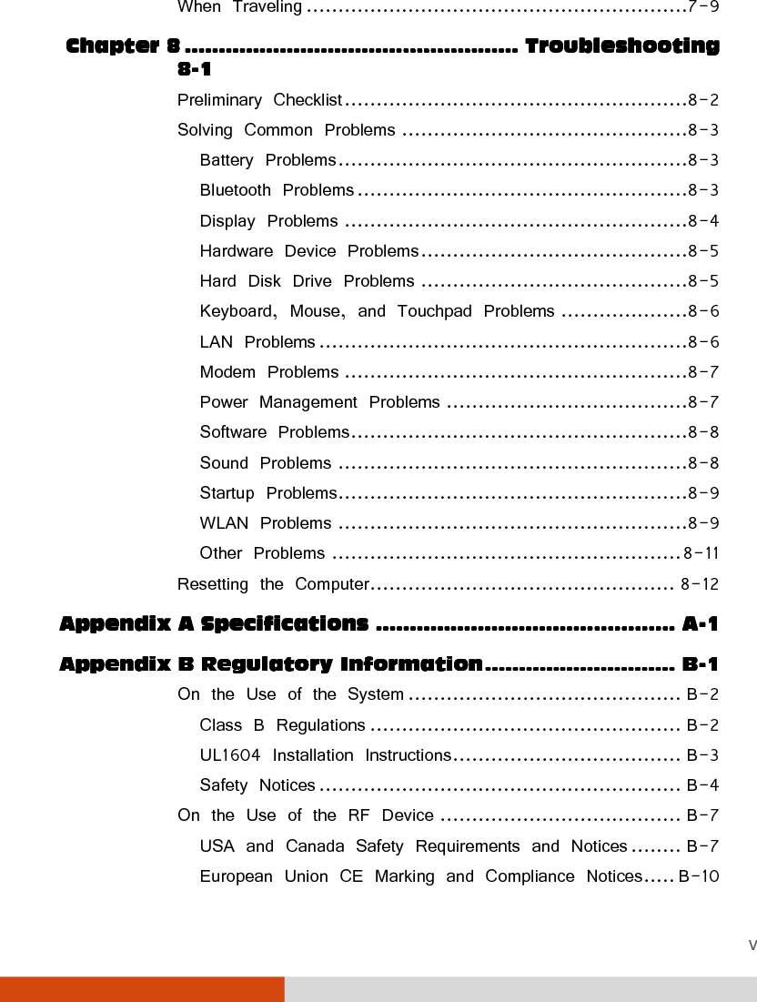
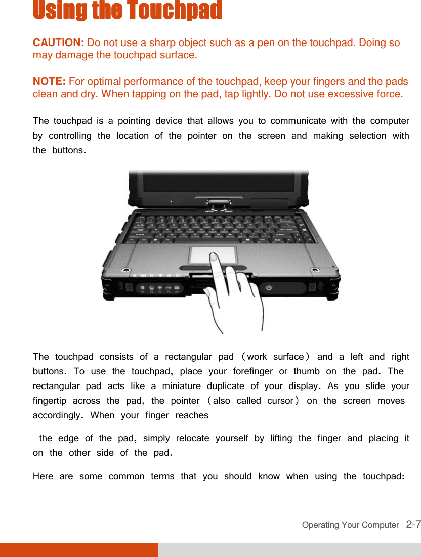
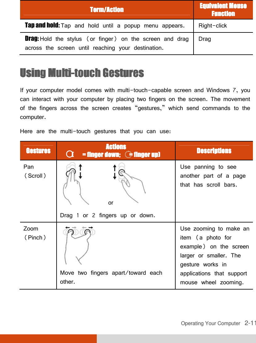
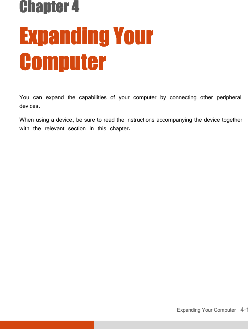
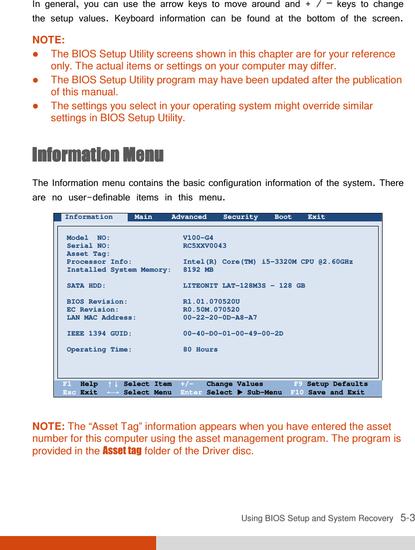
![5-6 Using BIOS Setup and System Recovery iRST Support enables of disables iRST, which gets your system up and running faster. Wake Up CapabilityWake Up CapabilityWake Up CapabilityWake Up Capability specifies events for waking up the system. Press Enter Enter Enter Enter to access the submenu as shown below. Advanced Wake Up Capability Item Specific Help Ring Wake Up From S3: USB Wake Up From S3: Wake on PCH LAN: [Disabled] [Disabled] [Disabled] Allow a modem activity to wake up the system from S3(Sleep) state. F1 Help ↑↓↑↓↑↓↑↓ Select Item +/- Change Values F9 Setup Defaults Esc Exit ←→←→←→←→ Select Menu Enter Select Sub-Menu F10 Save and Exit Ring Wake Up From S3 allows a modem device activity to wake up the system from S3 (Sleep) state. USB Wake Up From S3 allows a USB device activity to wake up the system from S3 (Sleep) state. Wake on PCH LAN allows a LAN activity to wake up the system from S3 (Sleep) state. System Policy System Policy System Policy System Policy sets if the system always runs at full speed (Performance) or lowers down when its temperature is too high (Balance). AC Initiation AC Initiation AC Initiation AC Initiation sets if connecting AC power will automatically start or resume your computer. SATA ModeSATA ModeSATA ModeSATA Mode set to AHCI if your hard disk supports AHCI. AHCI allows you to take advantage of Advanced Host Controller Interface features. The options are IDE and AHCI. CAUTION: Incorrect SATA mode settings can result in hard disk drive boot failure. Disabled](https://usermanual.wiki/Getac-Technology/047/User-Guide-1776980-Page-90.png)
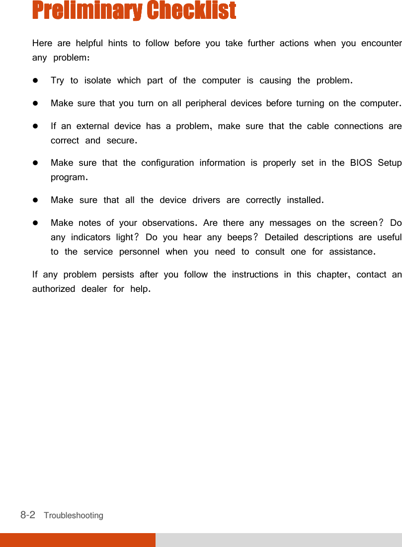
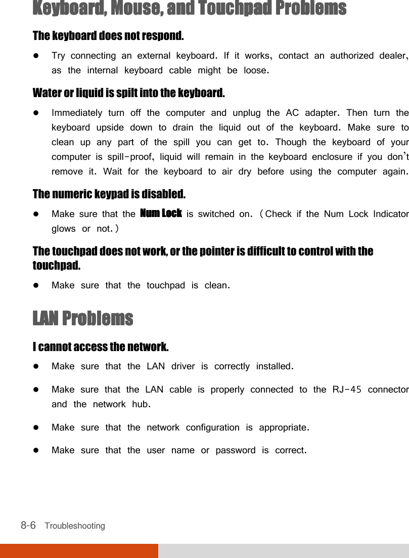
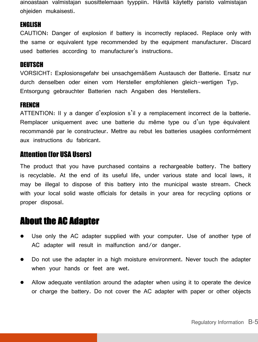
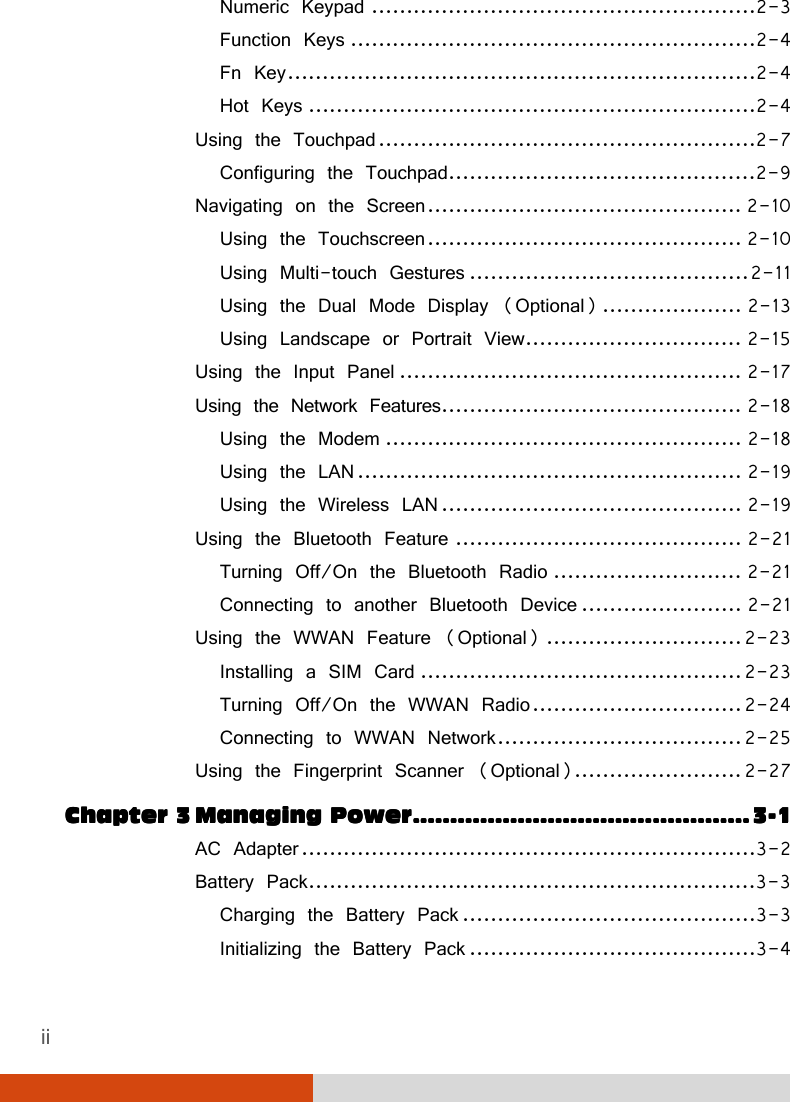
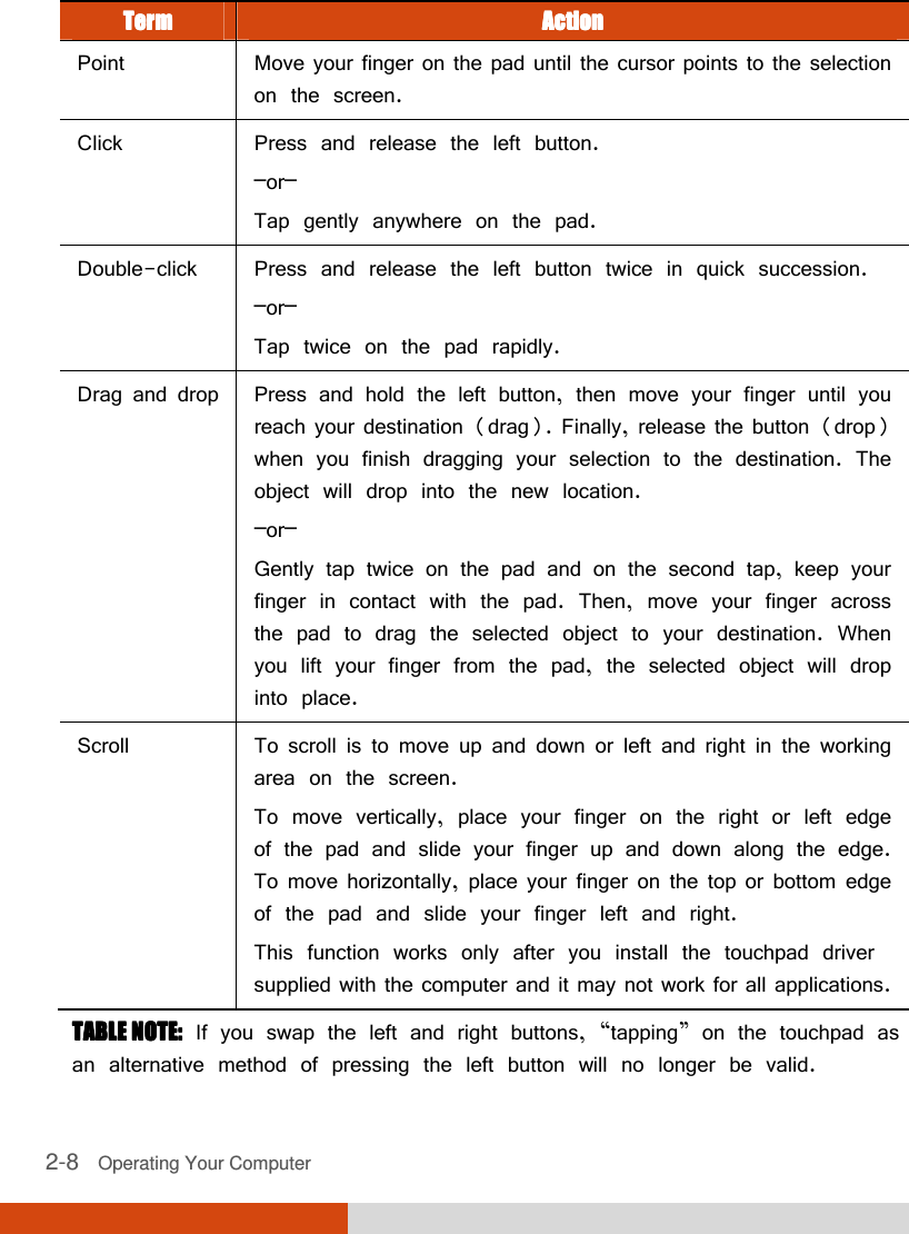
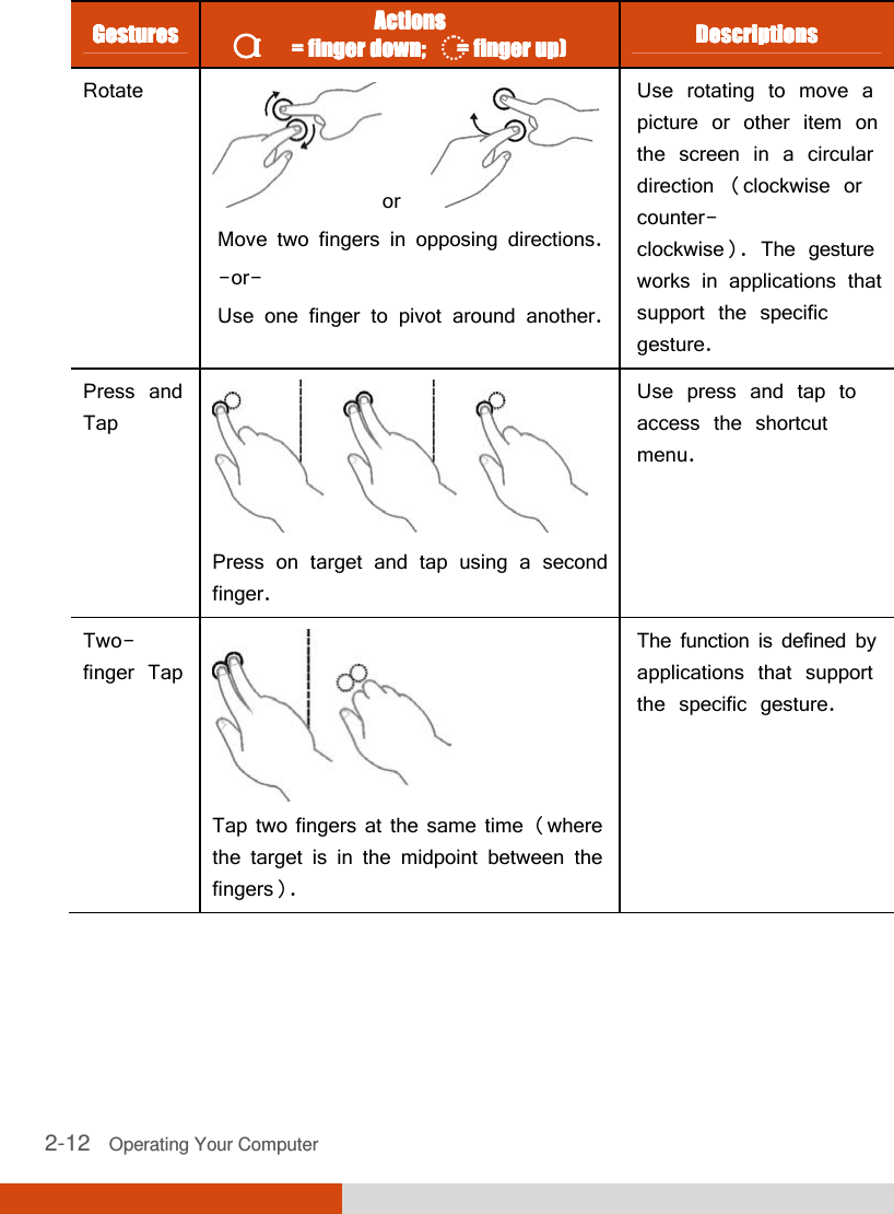
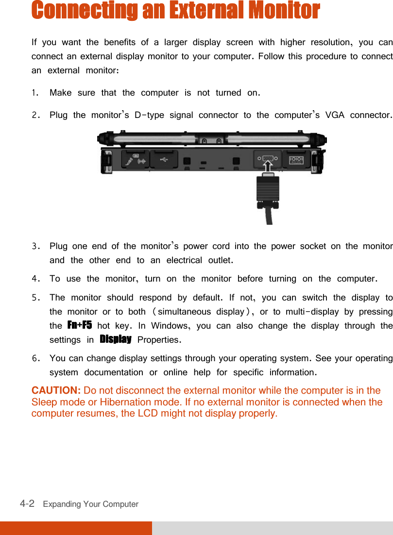
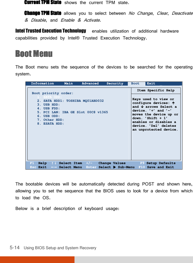
![Using BIOS Setup and System Recovery 5-7 AMT ConfigurationAMT ConfigurationAMT ConfigurationAMT Configuration configures Active Management Technology parameters. Press Enter Enter Enter Enter to access the submenu as shown below. Advanced AMT Configuration Item Specific Help Intel AMT: Intel AMT Setup Prompt: [Disable ] [Disabled] Enable/Disable Intel (R) Active Management Technology BIOS Extension. Note: iAMT H/W is always enabled. This option just controls the BIOS extension execution. If enabled this requires additional firmware in the SPI device F1 Help ↑↓↑↓↑↓↑↓ Select Item +/- Change Values F9 Setup Defaults Esc Exit ←→←→←→←→ Select Menu Enter Select Sub-Menu F10 Save and Exit Intel AMT enables or disables Intel® Active Management Technology BIOS extension execution. AMT allows the system administrator to access an AMT featured computer remotely. Intel AMT Setup PromptIntel AMT Setup PromptIntel AMT Setup PromptIntel AMT Setup Prompt determines whether the prompt for entering Intel AMT Setup appears or not during POST. If disabled, users cannot enter Intel AMT Setup. Virtualization Technology SetupVirtualization Technology SetupVirtualization Technology SetupVirtualization Technology Setup sets Virtualization Technology parameters. Press Enter Enter Enter Enter to access the submenu as shown below. Enabled](https://usermanual.wiki/Getac-Technology/047/User-Guide-1776980-Page-91.png)
![5-8 Using BIOS Setup and System Recovery Advanced Virtualization Technology Setup Item Specific Help Intel(R) Virtualization Technology Intel(R) VT for Directed I/O (VT-d) [Disabled] [Disabled] When enabled, a VMM can utilize the additional hardware capabilities. F1 Help ↑↓↑↓↑↓↑↓ Select Item +/- Change Values F9 Setup Defaults Esc Exit ←→←→←→←→ Select Menu Enter Select Sub-Menu F10 Save and Exit Intel(R) Virtualization TechnologyIntel(R) Virtualization TechnologyIntel(R) Virtualization TechnologyIntel(R) Virtualization Technology enables or disables Intel® VT (Intel Virtualization Technology) feature which provides hardware support for processor virtualization. When enabled, a VMM (Virtual Machine Monitor) can utilize the additional hardware virtualization capabilities provided by this technology. Intel(R) VT for Directed I/O (VTIntel(R) VT for Directed I/O (VTIntel(R) VT for Directed I/O (VTIntel(R) VT for Directed I/O (VT----d)d)d)d) enables or disables VT-d (Intel® Virtualization Technology for Directed I/O). When enabled, VT-d helps enhance Intel platforms for efficient virtualization of I/O devices. Graphics SetupGraphics SetupGraphics SetupGraphics Setup sets graphics related options. Press Enter Enter Enter Enter to access the submenu as shown below. Disabled](https://usermanual.wiki/Getac-Technology/047/User-Guide-1776980-Page-92.png)
![Using BIOS Setup and System Recovery 5-9 Advanced Graphic Setup Item Specific Help DVMT Pre-Allocated: Total Graphics Memory: [ ] [256MB] Select Pre-Allocated Graphics Memory size used by the Internal Graphics Device. This has no effect if external graphics are present. F1 Help ↑↓↑↓↑↓↑↓ Select Item +/- Change Values F9 Setup Defaults Esc Exit ←→←→←→←→ Select Menu Enter Select Sub-Menu F10 Save and Exit NOTE: Graphic Setup parameters apply to the internal graphics device only. DVMT PreDVMT PreDVMT PreDVMT Pre----Allocated Allocated Allocated Allocated sets the amount of pre-allocated (fixed) graphics memory for use by the internal graphics device. Total Graphics Memory Total Graphics Memory Total Graphics Memory Total Graphics Memory sets the amount of total graphics memory (pre-allocated + fixed + DVMT) for use by the internal graphics device. 64MB](https://usermanual.wiki/Getac-Technology/047/User-Guide-1776980-Page-93.png)
![5-10 Using BIOS Setup and System Recovery Device Configuration enables or disables several hardware components. Press Enter to access the submenu as shown below. Advanced Device Configuration Item Specific Help Wireless LAN: WWAN: Bluetooth: Media Card Reader: Smart Card Reader: HD Audio: Modem: Fingerprint Scanner: 1394 Port: Touch Screen: GPS: [ ] [Enabled] [Enabled] [Enabled] [Enabled] [Enabled] [Enabled] [Enabled] [Enabled] [Enabled] [Enabled] Set WLAN device to enable/disable. F1 Help ↑↓↑↓↑↓↑↓ Select Item +/- Change Values F9 Setup Defaults Esc Exit ←→←→←→←→ Select Menu Enter Select Sub-Menu F10 Save and Exit You can enable or disable the following items: Wireless LAN WWAN Bluetooth Media Card Reader (SD) Smart Card Reader HD Audio (High Definition Audio) Modem Fingerprint Scanner 1394 Port Touch Screen GPS Enabled](https://usermanual.wiki/Getac-Technology/047/User-Guide-1776980-Page-94.png)
![Using BIOS Setup and System Recovery 5-11 Serial COM Port Configuration enables or disables the serial port. Press Enter to access the submenu as shown below. Advanced COM PORT Configuration Item Specific Help Serial COM PORT1 Serial COM PORT2 Serial COM PORT3 [ ] [Enabled] [Enabled] This option controls the Onboard COM1 Address. When enabled, COM1 uses address 0x3F8h and IRQ4. F1 Help ↑↓↑↓↑↓↑↓ Select Item +/- Change Values F9 Setup Defaults Esc Exit ←→←→←→←→ Select Menu Enter Select Sub-Menu F10 Save and Exit Enabled](https://usermanual.wiki/Getac-Technology/047/User-Guide-1776980-Page-95.png)
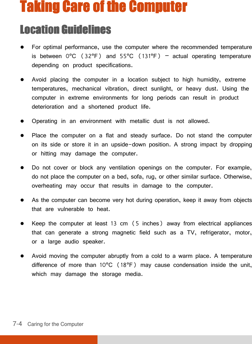
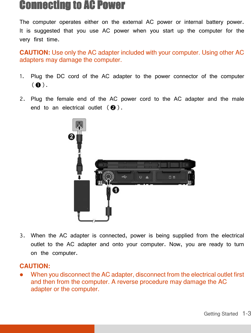
![5-12 Using BIOS Setup and System Recovery Security MenuSecurity MenuSecurity MenuSecurity Menu The Security menu contains the security settings, which safeguard your system against unauthorized use. Information Main Advanced Security Boot Exit Supervisor Password Is: User Password Is: Set Supervisor Password: Set User Password Password on Boot: Set HDD 0 Password: HDD 0 Password: TPM Setup Menu Intel Trusted Execution Technology Cleared Cleared [Enter] [Enter] [Disabled] [Enter] Cleared [Disabled] Item Specific Help Set or clear the Supervisor account’s password. F1 Help ↑↓↑↓↑↓↑↓ Select Item +/- Change Values F9 Setup Defaults Esc Exit ←→←→←→←→ Select Menu Enter Select Sub-Menu F10 Save and Exit NOTE: You can set the user password only when the supervisor password has been set. If both the administrator and user passwords are set, you can enter any of them for starting up the system and/or entering BIOS Setup. However, the user password only allows you to view/change the settings of certain items. A password setting is applied right after it is confirmed. To cancel a password, leave the password empty by pressing the Enter key. Supervisor/User Password Is Supervisor/User Password Is Supervisor/User Password Is Supervisor/User Password Is shows whether you have set the supervisor/user password or not for the system. Set Supervisor/User PasswordSet Supervisor/User PasswordSet Supervisor/User PasswordSet Supervisor/User Password sets the supervisor/user password. When typing the password, first make sure that Num Lock is off, and then type the password in the entry fields and press EnterEnterEnterEnter. Confirm your password by typing it again and pressing Enter](https://usermanual.wiki/Getac-Technology/047/User-Guide-1776980-Page-96.png)
![Using BIOS Setup and System Recovery 5-13 EnterEnterEnterEnter. You can set the supervisor/user password to be required for starting up the system and/or entering BIOS Setup. Password on BootPassword on BootPassword on BootPassword on Boot allows you to enable or disable the entering of password for booting up your system. Once the password is successfully set and this item is enabled, it is required for booting up the system. Set HDD Set HDD Set HDD Set HDD 0 Password0 Password0 Password0 Password sets the password for locking the Primary Master hard disk drive. After setting a password, the hard disk drive can only be unlocked by the password no matter where it is installed. HDD 0 Password Is HDD 0 Password Is HDD 0 Password Is HDD 0 Password Is shows whether you have set the hard disk password or not. TPM Setup MenuTPM Setup MenuTPM Setup MenuTPM Setup Menu sets various TPM parameters. Press Enter Enter Enter Enter to access the submenu as shown below. TTTTPM Support PM Support PM Support PM Support enables or disables TPM (Trusted Platform Module) support. TPM (Trusted Platform Module) is a component on your computer’s mainboard that is specifically designed to enhance platform security by providing a protected space for key operations and other security critical tasks. Security TPM Setup Menu Item Specific Help TPM Support: Current TPM State: Change TPM Status: [ ] [Enabled and Activated] [No Change] This is used to decide whether TPM support should be enabled or disabled. F1 Help ↑↓↑↓↑↓↑↓ Select Item +/- Change Values F9 Setup Defaults Esc Exit ←→←→←→←→ Select Menu Enter Select Sub-Menu F10 Save and Exit Enabled](https://usermanual.wiki/Getac-Technology/047/User-Guide-1776980-Page-97.png)


![6-34 Using Getac Software The default location is Users\[user name]\Pictures folder that contains the original images. A subfolder named Thumbs contains a copy of the same images (with filename prefix Thumb_) for the thumbnail view. NOTE: If you are adding or deleting images using File Explorer, make sure to work on both the correct folder and its Thumbs subfolder. ItemsItemsItemsItems NameNameNameName DescriptionsDescriptionsDescriptionsDescriptions Time Option Displays the time throughout the program according to one of the two choices: System time zone (default) The time zone setting of the computer is taken into consideration. If the current location is in daylight saving time, the time will be adjusted accordingly. UTC The time is based on Coordinated Universal Time. Filename Prefix The default filename prefix is IMG. The complete filename is IMG_xxxxxx.jpg (where xxxxxx = sequential number). When the sequential number has reached 999999 and you are taking the next picture, a message will pop up to ask you to change the prefix. You can change the prefix by typing the characters (limited to A~Z, a~z, 0~9, - and _) in the entry field. Maximum number of characters allowed is 10.](https://usermanual.wiki/Getac-Technology/047/User-Guide-1776980-Page-138.png)