Getac Technology 048 Notebook Computer User Manual
Getac Technology Corp. Notebook Computer
Contents
- 1. User manual - Pt 1
- 2. User manual - Pt 2
- 3. Users manual - Pt 1
- 4. Users manual - Pt 2
User manual - Pt 1

Rugged Mobile Computing Solutions
V200
USER’S MANUAL

Aug. 2012
TRADEMARKS
TRADEMARKSTRADEMARKS
TRADEMARKS
The Bluetooth® word mark and logos are owned by the Bluetooth SIG, Inc. All brand
and product names are trademarks or registered trademarks of their respective
companies.
NOTE
NOTENOTE
NOTE
The information in this manual is subject to change without notice.
Most screens and operating instructions in this manual are based on Windows 7.
If you’re using a different version of Windows, the screens and related operations

may not be the same.
For the latest version of the manual, please visit the Getac website at www.getac.com.
ENERGY STAR® is a government program that offers businesses and consumers
energy-efficient solutions, making it easy to save money while protecting the
environment for future generations.
Please reference ENERGY STAR® related information from www.energystar.gov.
As an ENERGY STAR® Partner, Getac Technology Corporation has determined that
this product meets the ENERGY STAR® guidelines for energy efficiency.
An ENERGY STAR® qualified computer uses 70 % less electricity than computers
without enabled power management features.
Earning the
Earning the Earning the
Earning the E
EE
ENERGY
NERGY NERGY
NERGY S
SS
STAR
TARTAR
TAR®
®®
®
When every home office is powered by equipment that has earned the ENERGY
STAR®, the change will keep over 289 billion pounds of greenhouse gases out
of the air.
If left inactive, ENERGY STAR® qualified computers enter a low-power mode
and may use 15 watts or less. New chip technologies make power management
features more reliable, dependable, and user-friendly than even just a few years
ago.
Spending a large portion of time in low-power mode not only saves energy,
but helps equipment run cooler and last longer.

Businesses that use ENERGY STAR® enabled office equipment may realize
additional savings on air conditioning and maintenance.
Over its lifetime, ENERGY STAR® qualified equipment in a single home office
(e.g., computer, monitor, printer, and fax) can save enough electricity to light
an entire home for more than 4 years.
Power management (“sleep settings”) on computers and monitors can result
in much savings annually.
Remember, saving energy prevents pollution
Remember, saving energy prevents pollutionRemember, saving energy prevents pollution
Remember, saving energy prevents pollution
Because most computer equipment is left on 24 hours a day, power management
features are important for saving energy and are an easy way to reduce air pollution.
By using less energy, these products help lower consumers’ utility bills, and prevent
greenhouse gas emissions.

i
Table of Contents
Table of ContentsTable of Contents
Table of Contents
Chapter 1
Chapter 1Chapter 1
Chapter 1
G
GG
Getting Started
etting Startedetting Started
etting Started
................................
................................................................
..............................................
............................
..............
1
11
1-
--
-1
11
1
Getting the Computer Running ......................................... 1-2
Unpacking ................................................................ 1-2
Connecting to AC Power ............................................ 1-3
Opening and Closing the Cover ................................... 1-4
Operating in Tablet Mode ........................................... 1-5
Turning On and Off the Computer ............................... 1-7
Taking a Look at the Computer ...................................... 1-8
Front Components ..................................................... 1-8
Rear Components ..................................................... 1-10
Right-Side Components ............................................. 1-11
Left-Side Components ............................................... 1-12
Top-open Components .............................................. 1-13
Bottom Components .................................................. 1-15
Using the Accessories .................................................. 1-17
Using the Tether ..................................................... 1-17
Attaching the Handgrip Strap ...................................... 1-18
Attaching the Shoulder Strap ...................................... 1-18
Chapter
Chapter Chapter
Chapter 2
22
2
O
OO
Operating Your Computer
perating Your Computerperating Your Computer
perating Your Computer
.............................
..........................................................
.............................
2
22
2-
--
-1
11
1
Using the Internal Keyboard ............................................2-2
Typewriter Keys ........................................................2-2
Cursor-Control Keys ..................................................2-2

ii
Numeric Keypad .......................................................2-3
Function Keys ..........................................................2-4
Fn Key ...................................................................2-4
Hot Keys ................................................................2-4
Using the Touchpad ......................................................2-7
Configuring the Touchpad ............................................2-9
Navigating on the Screen ............................................. 2-10
Using the Touchscreen ............................................. 2-10
Using Multi-touch Gestures ........................................ 2-11
Using the Dual Mode Display (Optional) .................... 2-13
Using Landscape or Portrait View ............................... 2-15
Using the Input Panel ................................................. 2-17
Using the Network Features ........................................... 2-18
Using the Modem ................................................... 2-18
Using the LAN ....................................................... 2-19
Using the Wireless LAN ........................................... 2-19
Using the Bluetooth Feature ......................................... 2-21
Turning Off/On the Bluetooth Radio ........................... 2-21
Connecting to another Bluetooth Device ....................... 2-21
Using the WWAN Feature (Optional) ............................ 2-23
Installing a SIM Card .............................................. 2-23
Turning Off/On the WWAN Radio .............................. 2-24
Connecting to WWAN Network ................................... 2-25
Using the Fingerprint Scanner (Optional)........................ 2-27
Chapter
Chapter Chapter
Chapter 3
33
3
M
MM
Managing
anaging anaging
anaging Power
PowerPower
Power
................................
................................................................
.............................................
..........................
.............
3
33
3-
--
-1
11
1
AC Adapter .................................................................3-2
Battery Pack ................................................................3-3
Charging the Battery Pack ..........................................3-3
Initializing the Battery Pack .........................................3-4

iii
Checking the Battery Level .........................................3-4
Replacing the Battery Pack .........................................3-5
Battery Low Signals and Actions ..................................3-6
Power Management .......................................................3-8
Hibernation ...............................................................3-9
Power-Saving Tips ..................................................... 3-10
Chapter
Chapter Chapter
Chapter 4
44
4
E
EE
Expanding Your Computer
xpanding Your Computerxpanding Your Computer
xpanding Your Computer
............................
........................................................
............................
4
44
4-
--
-1
11
1
Connecting an External Monitor .......................................4-2
Connecting a Serial Device.............................................4-3
Connecting a USB Device ..............................................4-4
Connecting an IEEE 1394 Device ....................................4-5
Connecting Audio Devices ..............................................4-6
Using ExpressCards ......................................................4-7
Using PC Cards...........................................................4-9
Using Smart Cards (Optional) ...................................... 4-11
Using Storage Cards ................................................... 4-12
System Memory Upgrade.............................................. 4-13
Chapter
Chapter Chapter
Chapter 5
55
5
U
UU
Using BIOS Setup and System Recovery
sing BIOS Setup and System Recoverysing BIOS Setup and System Recovery
sing BIOS Setup and System Recovery
......
............
......
5
55
5-
--
-1
11
1
BIOS Setup .................................................................5-2
When and How to Use .............................................5-2
Information Menu ......................................................5-3
Main Menu ..............................................................5-4
Advanced Menu ........................................................5-5
Security Menu ........................................................ 5-12
Boot Menu ............................................................ 5-14
Exit Menu ............................................................. 5-15
System Recovery ........................................................ 5-17

iv
Chapter
Chapter Chapter
Chapter 6
66
6
U
UU
Using Getac Software
sing Getac Softwaresing Getac Software
sing Getac Software
................................
................................................................
....................................
........
....
6
66
6-
--
-1
11
1
Using the OSD Control Panel .........................................6-2
Quick Button Setup ...................................................6-6
Using Button Manager ...................................................6-8
Using G-Manager ....................................................... 6-10
Starting G-Manager ................................................. 6-10
System Tab ............................................................ 6-11
Battery Tab ........................................................... 6-12
ECO Tab .............................................................. 6-14
Light Sensor Tab .................................................... 6-16
Ignition Tab ........................................................... 6-18
Monitoring Tab ....................................................... 6-19
GPS Status Tab ..................................................... 6-20
Using Getac Camera ................................................... 6-22
Taking Pictures ....................................................... 6-24
Shooting Videos ...................................................... 6-26
Using View Mode ................................................... 6-27
Camera Settings ..................................................... 6-31
Chapter
Chapter Chapter
Chapter 7
77
7
C
CC
Caring for the Computer
aring for the Computeraring for the Computer
aring for the Computer
...............................
..............................................................
...............................
7
77
7-
--
-1
11
1
Protecting the Computer .................................................7-2
Using an Anti-Virus Strategy .......................................7-2
Using Action Center (for Windows 7) .........................7-2
Using the Cable Lock ................................................7-3
Taking Care of the Computer .........................................7-4
Location Guidelines ....................................................7-4
General Guidelines ....................................................7-5
Cleaning Guidelines ...................................................7-5
Battery Pack Guidelines ..............................................7-6
Touchscreen Guidelines...............................................7-7

v
When Traveling ............................................................7-9
Chapter
Chapter Chapter
Chapter 8
88
8
................................
................................................................
.................................................
..................................
.................
T
TT
Troubleshooting
roubleshootingroubleshooting
roubleshooting
8
88
8-
--
-1
11
1
Preliminary Checklist ......................................................8-2
Solving Common Problems .............................................8-3
Battery Problems .......................................................8-3
Bluetooth Problems ....................................................8-3
Display Problems ......................................................8-4
Hardware Device Problems ..........................................8-5
Hard Disk Drive Problems ..........................................8-5
Keyboard, Mouse, and Touchpad Problems ....................8-6
LAN Problems ..........................................................8-6
Modem Problems ......................................................8-7
Power Management Problems ......................................8-7
Software Problems .....................................................8-8
Sound Problems .......................................................8-8
Startup Problems .......................................................8-9
WLAN Problems .......................................................8-9
Other Problems ....................................................... 8-11
Resetting the Computer ................................................ 8-12
Appendix A S
Appendix A SAppendix A S
Appendix A Specifications
pecificationspecifications
pecifications
................................
................................................................
............................................
........................
............
A
AA
A-
--
-1
11
1
Appendix
Appendix Appendix
Appendix B R
B RB R
B Regulatory Information
egulatory Informationegulatory Information
egulatory Information
............................
........................................................
............................
B
BB
B-
--
-1
11
1
On the Use of the System ........................................... B-2
Class B Regulations ................................................. B-2
UL1604 Installation Instructions .................................... B-3
Safety Notices ......................................................... B-4
On the Use of the RF Device ...................................... B-7
USA and Canada Safety Requirements and Notices ........ B-7
European Union CE Marking and Compliance Notices ..... B-10

vi

Getting Started 1-1
Chapter 1
Chapter 1Chapter 1
Chapter 1
Getting Started
Getting StartedGetting Started
Getting Started
Congratulations on purchasing this rugged computer.
This chapter first tells you step by step how to get the computer up and running.
Then, you will find a section briefly introducing the external components of the
computer.

1-2 Getting Started
Getting the Computer Running
Getting the Computer RunningGetting the Computer Running
Getting the Computer Running
This section guides you through the procedures for getting the computer ready for
operation.
Unpacking
UnpackingUnpacking
Unpacking
After unpacking the shipping carton, you should find these standard items:
Notebook computer
Accessories:
− AC adapter
− AC power cord
− Shoulder strap
− Handgrip strap
− Stylus and tether
− Digitizer pen (option)
− Driver disc
− Documents
Inspect all the items. If any item is damaged or missing, notify your dealer immediately.
Keep the shipping carton and packing materials in case you need to ship or store
the computer in the future.
Getting Started 1-3
Connecting to AC Power
Connecting to AC PowerConnecting to AC Power
Connecting to AC Power
The computer operates either on the external AC power or internal battery power.
It is suggested that you use AC power when you start up the computer for the
very first time.
CAUTION: Use only the AC adapter included with your computer. Using other AC
adapters may damage the computer.
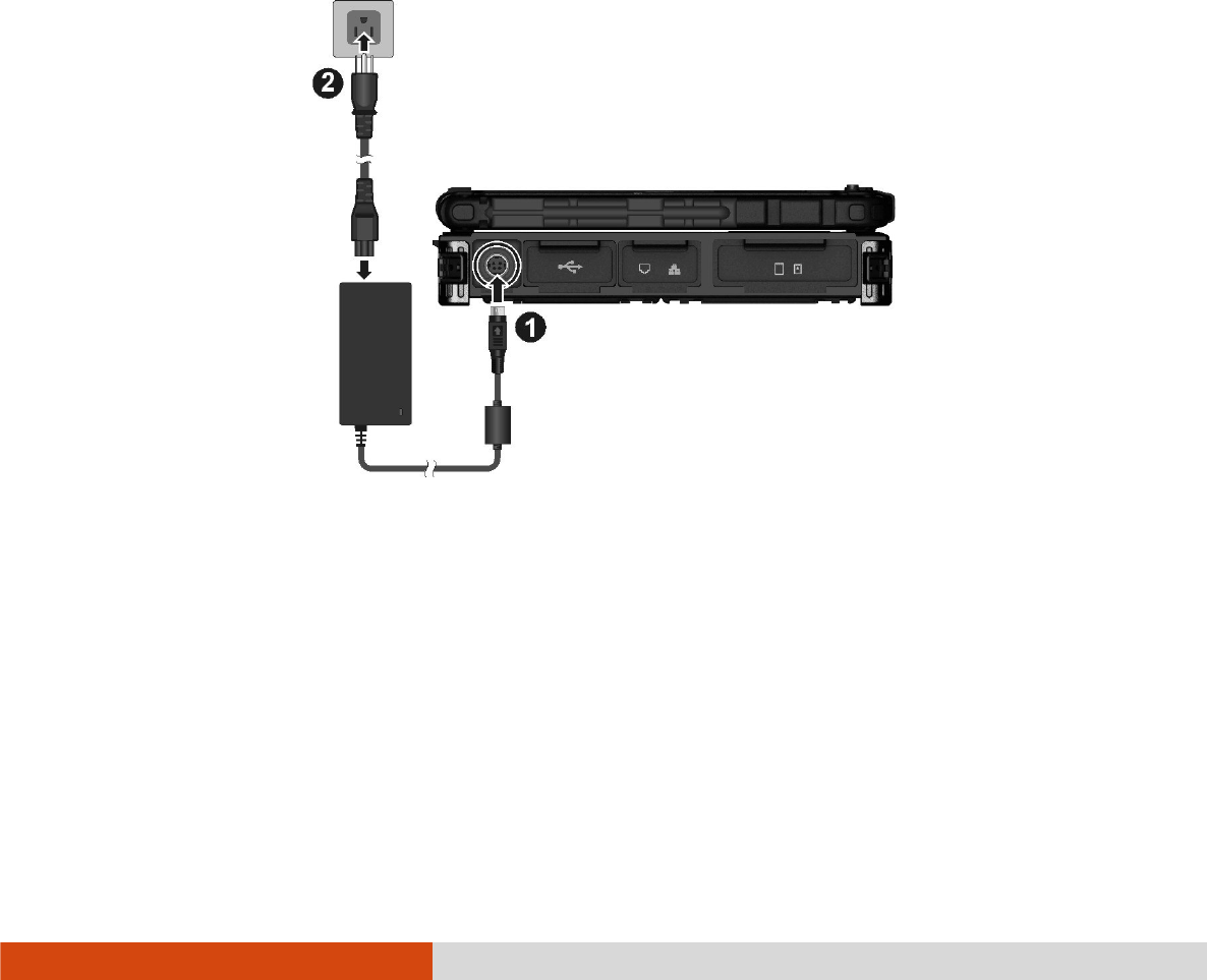
1. Plug the DC cord of the AC adapter to the power connector of the computer
().
2. Plug the female end of the AC power cord to the AC adapter and the male
end to an electrical outlet ().
3. When the AC adapter is connected, power is being supplied from the electrical
outlet to the AC adapter and onto your computer. Now, you are ready to turn
on the computer.
CAUTION:
When you disconnect the AC adapter, disconnect from the electrical outlet first
and then from the computer. A reverse procedure may damage the AC
adapter or the computer.
1-4 Getting Started
When unplugging the connector, always hold the plug head. Never pull on the
cord.
NOTE: When the AC adapter is connected, it also charges the battery pack. For
information on using battery power, see Chapter 3.
Opening and Closing the Cover
Opening and Closing the CoverOpening and Closing the Cover
Opening and Closing the Cover
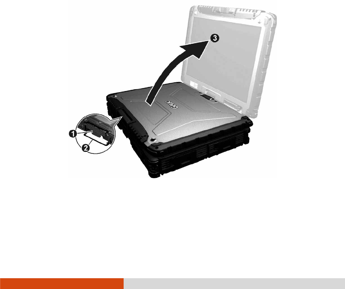
To open the top cover:
1. Pull loose the cover latch () and release the clamp ().
2. Lift up the cover (). You can tilt the cover forward or backward for optimal
viewing clarity.
To close the top cover:
1. Close the display.
Getting Started 1-5
2. Lift the cover latch and engage the clamp on the display. Then, push in the
cover latch to click it into place.
Operating in Tablet Mode
Operating in Tablet ModeOperating in Tablet Mode
Operating in Tablet Mode
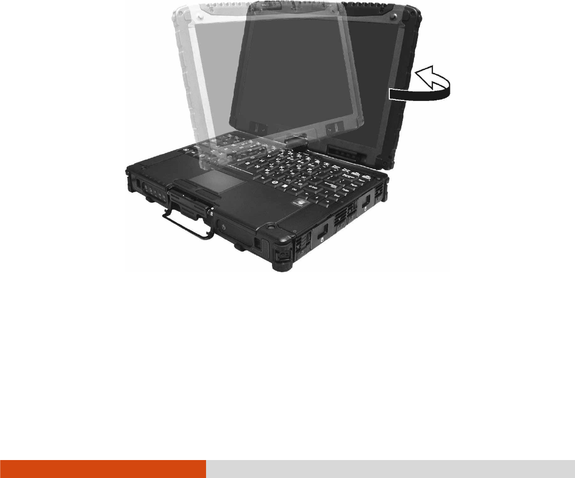
In addition to being used as a regular notebook computer (Laptop mode), your
computer can also be operated in Tablet mode. In Tablet mode, you operate the
computer with a stylus or digitizer pen, or a fingertip, instead of a keyboard or mouse.
1. Open the top cover so that it is almost perpendicular with the keyboard of the
computer.
2. Turn the display counter-clockwise by 165o.
CAUTION: Do not rotate the display more than 165o, or attempt to rotate the
display clockwise.
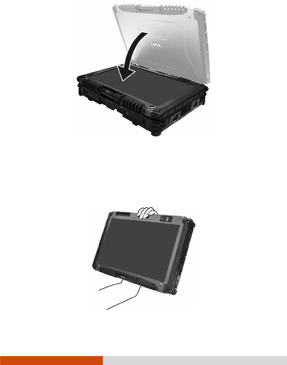
3. Close the computer with the display facing up.
1-6 Getting Started
4. Lift the cover latch and engage the clamp on the display. Then, push in the
cover latch to click it into place.
In Tablet mode, the computer can be operated while holding it as shown. A handgrip
strap is supplied to help you hold the computer. (See “Attaching the Handgrip Strap”
in this chapter for installation instructions.)
Getting Started 1-7
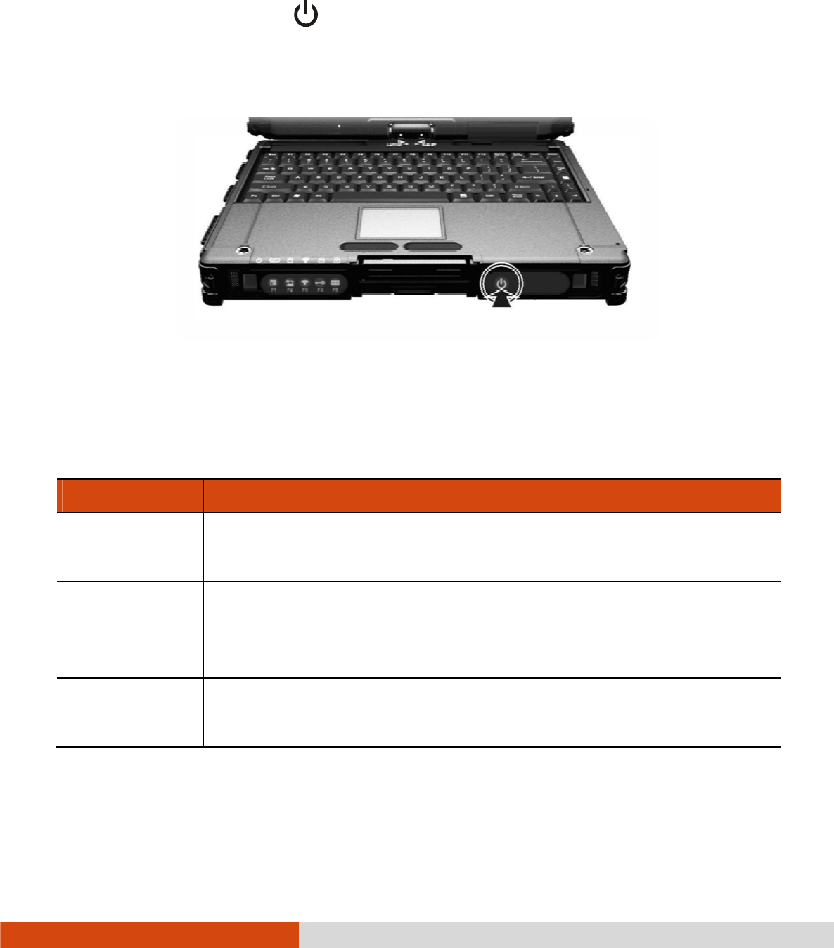
Turning On and Off the Computer
Turning On and Off the ComputerTurning On and Off the Computer
Turning On and Off the Computer
Turning On
Turning OnTurning On
Turning On
Press the power button (
). Each time the computer is turned on, it performs
a Power-On Self Test (POST), and the operating system such as Windows should
start.
Turning O
Turning OTurning O
Turning Off
ffff
ff
When you finish a working session, you can stop the system by turning off the power
or leaving it in Sleep or Hibernation mode:
To...
To...To...
To...
Do this...
Do this...Do this...
Do this...
Power off
(Shutdown)
Use the Windows Start menu in the lower left and follow the
shutdown procedure.
Sleep Press the power button*.
–or–
Use the Windows Start menu to put the computer in Sleep mode.
Hibernate Use the Windows Start menu to put the computer in Hibernation
mode. (See “Hibernation” in Chapter 3 for more information.)
* “Sleep” is the default setting of the power button. You may change what the
power button does in Windows Control Panel.
1-8 Getting Started
Taking a Look at the Computer
Taking a Look at the ComputerTaking a Look at the Computer
Taking a Look at the Computer
NOTE:
Depending on the model you purchased, the appearance of your computer
may not be exactly the same as those shown in this manual.
You need to open the protective covers to access the connectors. When not
using a connector, make sure to close the cover completely for water- and
dust-proof integrity. (Engage the locking mechanism if existing.)
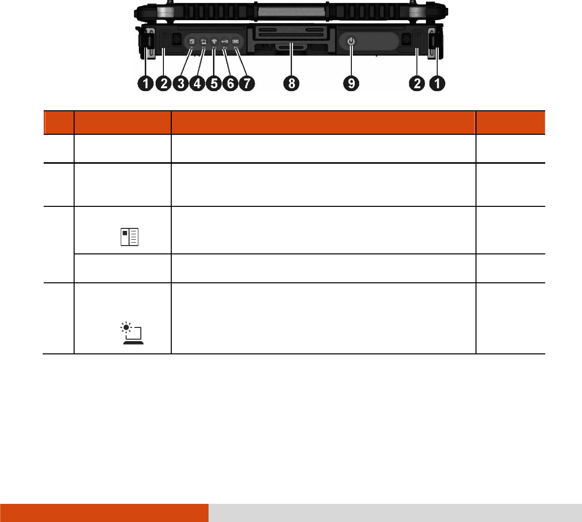
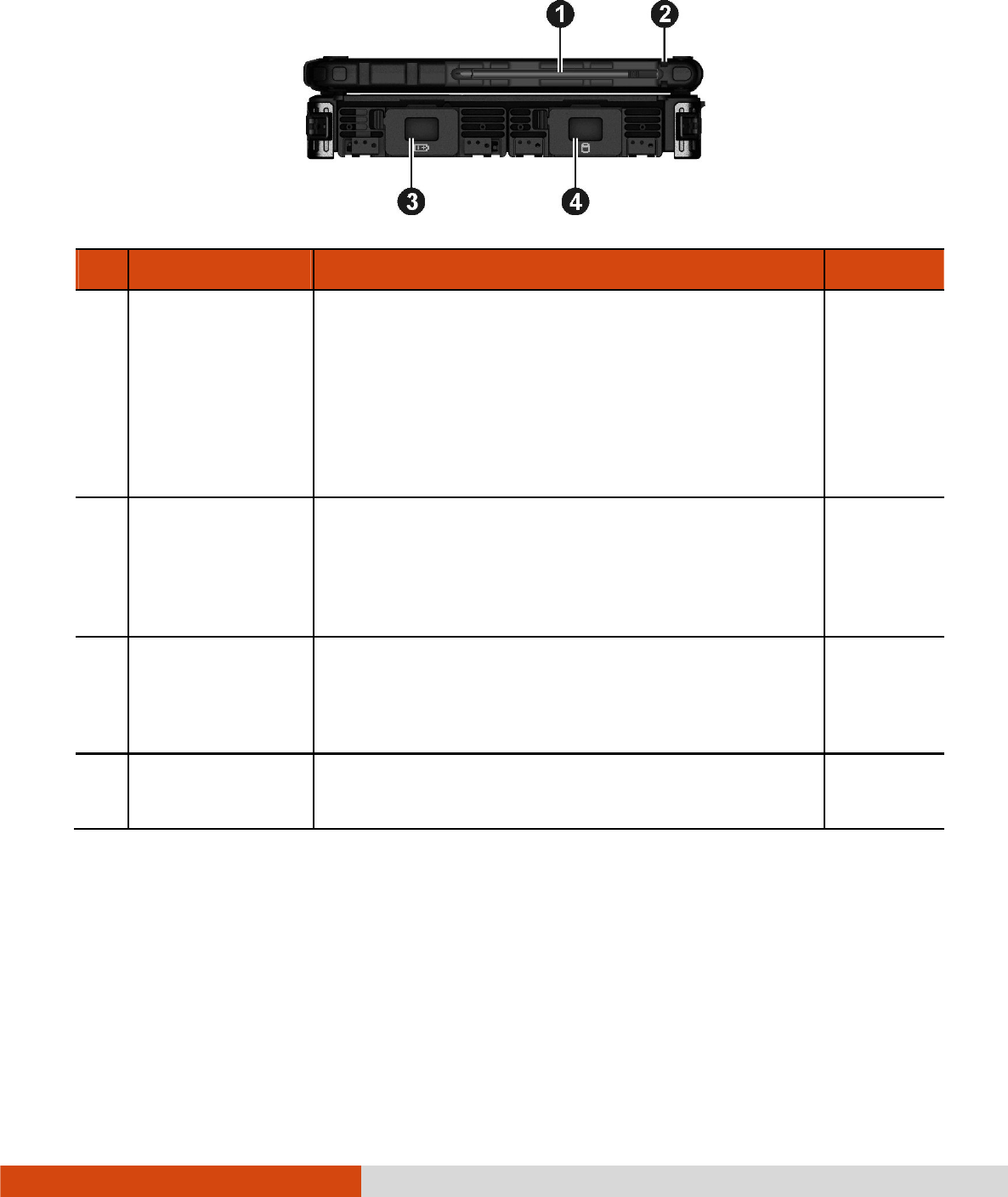
Front Components
Front ComponentsFront Components
Front Components
Ref
RefRef
Ref
Component
ComponentComponent
Component
Description
DescriptionDescription
Description
See Also
See AlsoSee Also
See Also
Strap Holder
Strap HolderStrap Holder
Strap Holder
Two buckles hold the shoulder strap. P. 1-18
Stereo
Stereo Stereo
Stereo
Speaker
SpeakerSpeaker
Speaker
Sends out sound and voice from your computer.
OSD Control
OSD Control OSD Control
OSD Control
Button
Button Button
Button
Opens or closes the OSD (On Screen Display)
control panel.
P. 6-2
P1 Button
P1 ButtonP1 Button
P1 Button
Can be re-defined using the Button Manager utility. P. 6-8
Sunlight
SunlightSunlight
Sunlight-
--
-
rea
rearea
readable
dable dable
dable
Button
ButtonButton
Button
Toggles the sunlight-readable mode on or off.
In sunlight-readable mode, the display brightness
is increased to the highest level.
Getting Started 1-9
Ref
RefRef
Ref
Component
ComponentComponent
Component
Description
DescriptionDescription
Description
See Also
See AlsoSee Also
See Also
CAUTION: To prevent burns to your fingers if
using the computer (especially in Tablet Mode)
with sunlight-readable mode turned on, do wear
gloves when touching the top portion of the LCD
display as it may be hot to the touch.
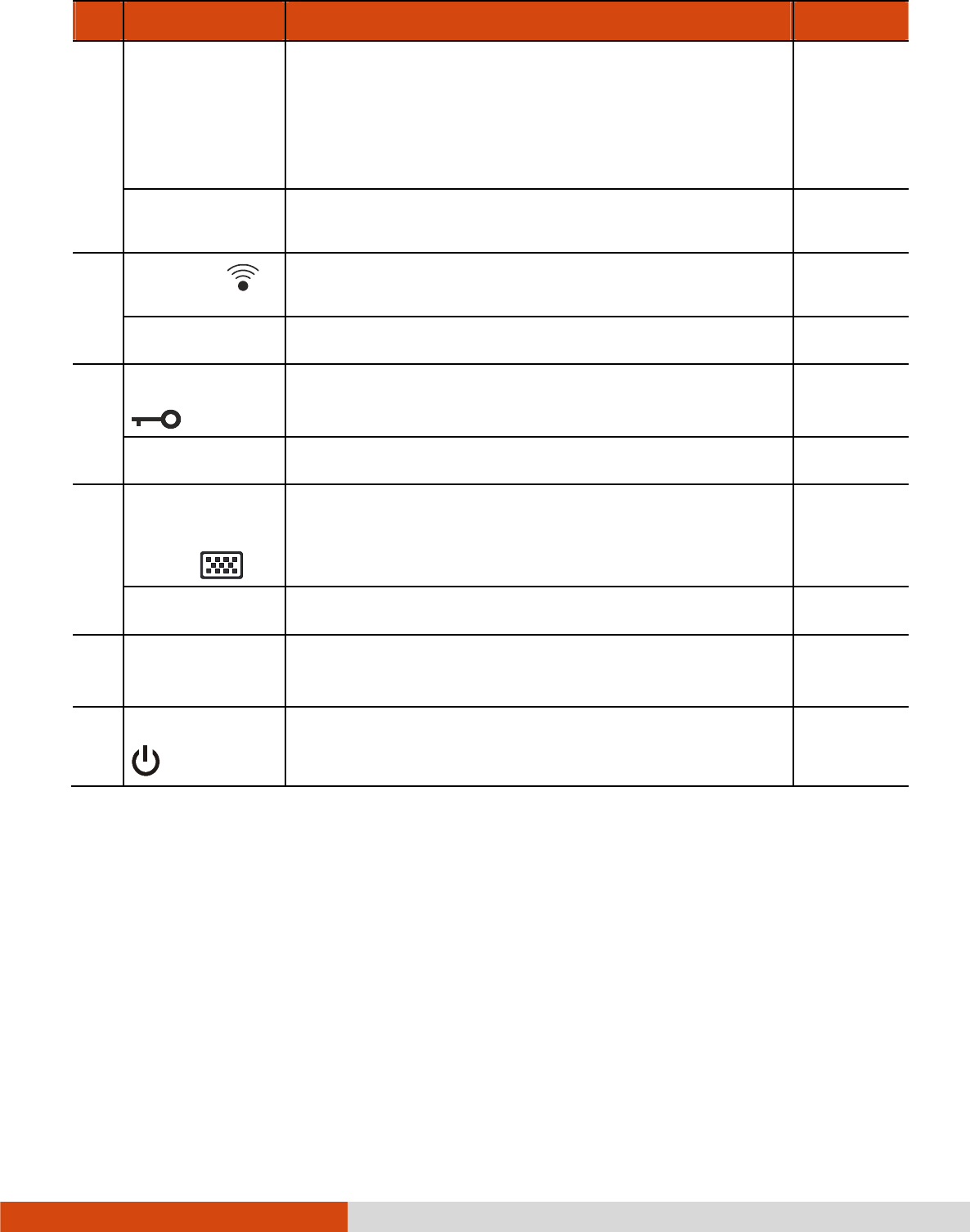
P2
P2P2
P2
Button
ButtonButton
Button
Can be re-defined using the Button Manager utility. P. 6-8
RF Button
RF Button RF Button
RF Button
Serves as the master on/off control of the RF radio.
P3
P3P3
P3
Button
ButtonButton
Button
Can be re-defined using the Button Manager utility. P. 6-8
Reset Button
Reset Button Reset Button
Reset Button
Serves as the Ctrl
CtrlCtrl
Ctrl+Alt
AltAlt
Alt+Del
DelDel
Del keyboard keys. P. 8-12
P4
P4P4
P4
Button
ButtonButton
Button
Can be re-defined using the Button Manager utility. P. 6-8
Software
Software Software
Software
Keyboard
Keyboard Keyboard
Keyboard
Button
Button Button
Button
Opens or closes the software keyboard on your
screen.
P. 2-17
P5
P5P5
P5
Button
ButtonButton
Button
Can be re-defined using the Button Manager utility. P. 6-8
Top Cover
Top Cover Top Cover
Top Cover
Latch
LatchLatch
Latch
Locks the top cover. P. 1-4
Power
Power Power
Power Button
ButtonButton
Button
Turns the power on or off (Sleep mode by
default).
P. 1-7
1-10 Getting Started
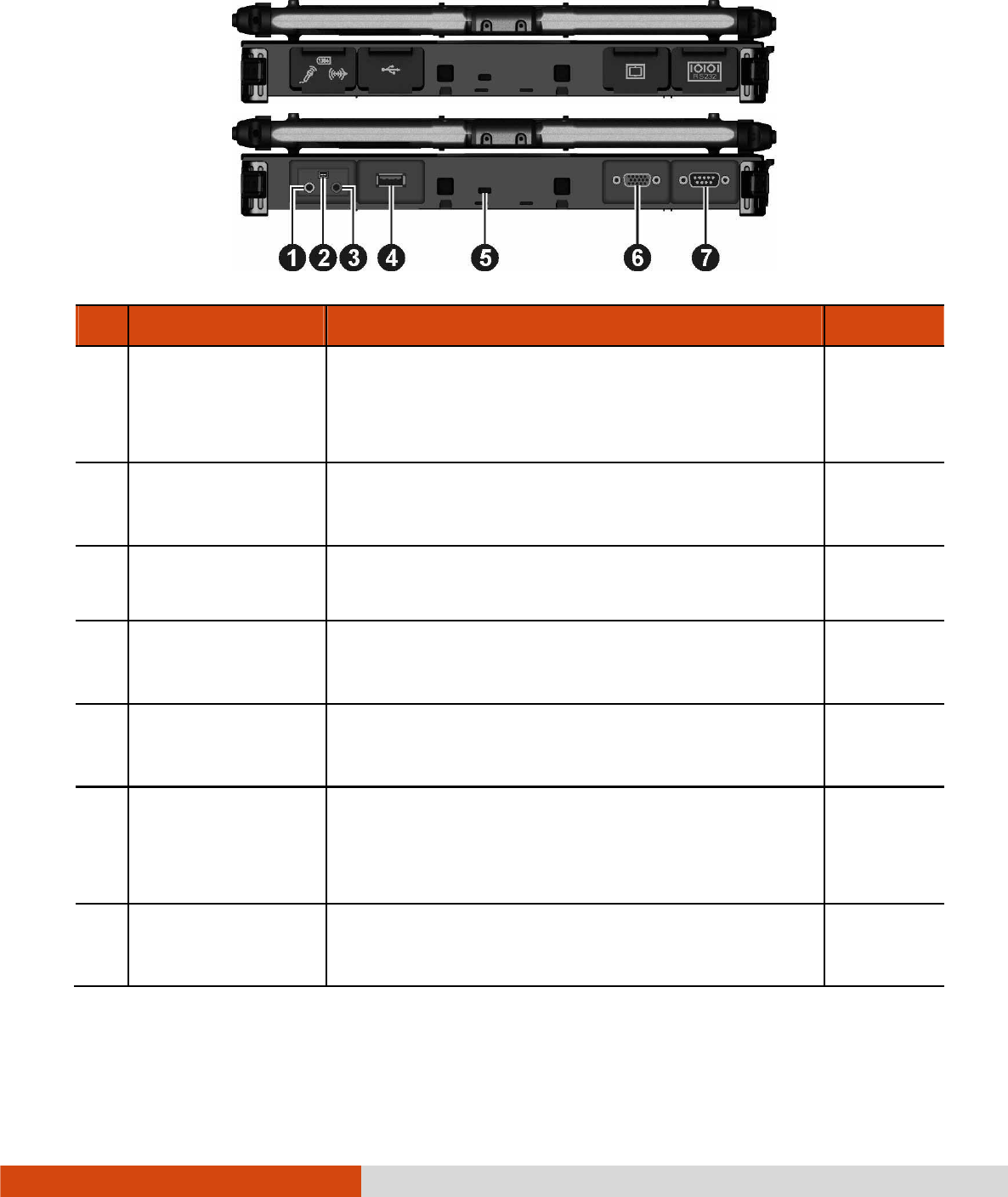
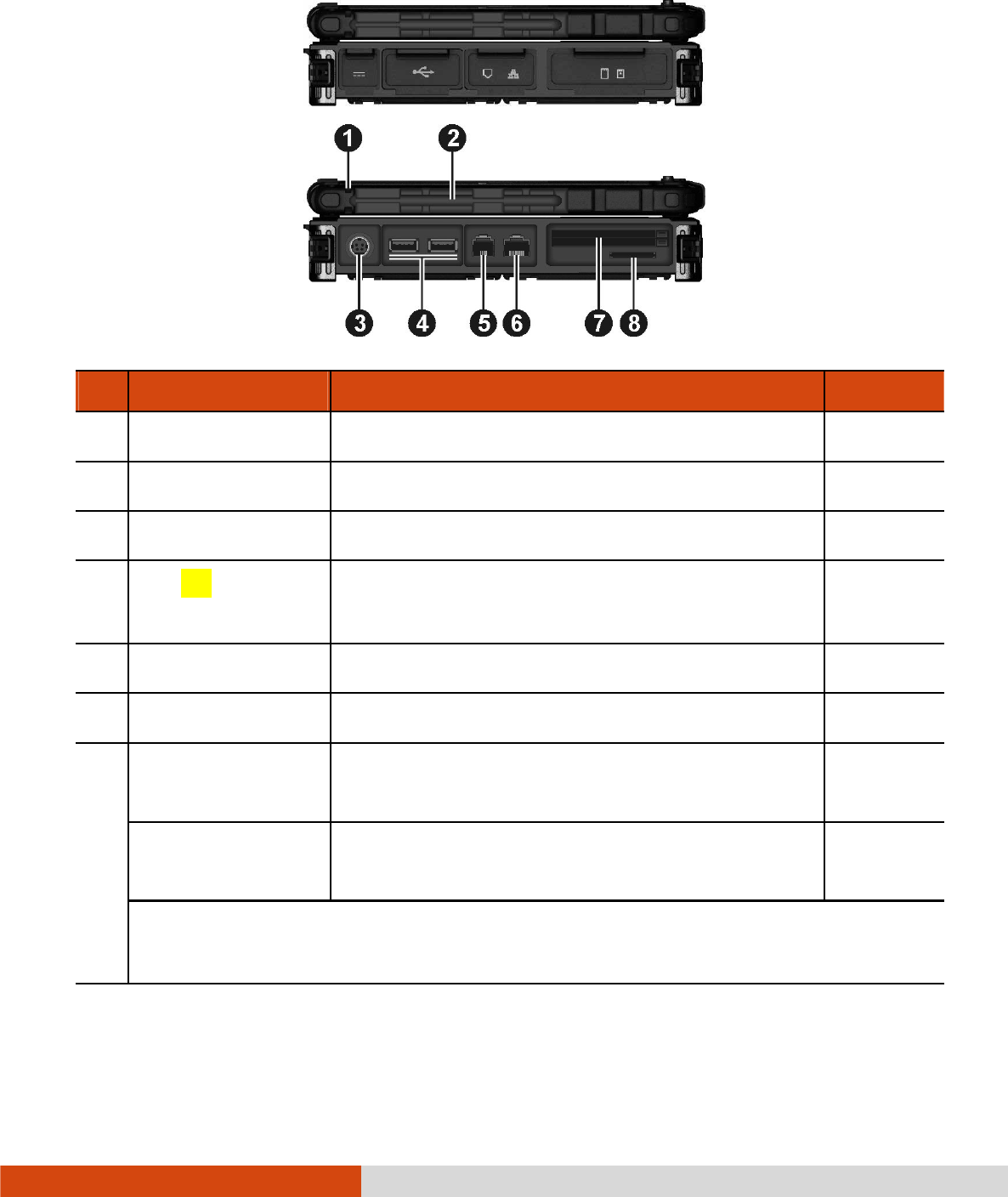
Rear Components
Rear ComponentsRear Components
Rear Components
Ref
RefRef
Ref
Component
ComponentComponent
Component
Description
DescriptionDescription
Description
See Also
See AlsoSee Also
See Also
Audio Output
Audio Output Audio Output
Audio Output
Connector
ConnectorConnector
Connector
Connects a set of headphones, external
speakers with amplifier, or an audio recording
device.
P. 4-6
Mini IEEE 1394
Mini IEEE 1394 Mini IEEE 1394
Mini IEEE 1394
Port
PortPort
Port
Connects an IEEE 1394 device such as a
scanner, printer, DVCAM, and VCR.
P. 4-5
Microphone
Microphone Microphone
Microphone
Connector
ConnectorConnector
Connector
Connects an external microphone. P. 4-6
USB 2.0 Port
USB 2.0 PortUSB 2.0 Port
USB 2.0 Port
Connects a USB device, such as a flash disk,
printer, digital camera, joystick, and more.
P. 4-4
Kensington Lock
Kensington LockKensington Lock
Kensington Lock
Locks the computer to a stationary object for
security.
P. 7-3
VGA Connector
VGA ConnectorVGA Connector
VGA Connector
Connects an external display monitor.
(Depending on your model, this port could be
a serial connector.)
P. 4-2
Serial Connector
Serial ConnectorSerial Connector
Serial Connector
Connects a serial mouse or serial communication
device.
P. 4-3
Getting Started 1-11
Right
RightRight
Right-
--
-Side Components
Side ComponentsSide Components
Side Components
Ref
RefRef
Ref
Component
ComponentComponent
Component
Description
DescriptionDescription
Description
See Also
See AlsoSee Also
See Also
Stylus
StylusStylus
Stylus
Serves as the input device by tapping on the
touchscreen to make selections and enter
information.
NOTE: Some models do not have the stylus
slot on this side, so you can only use the slot on
the left side for storing the stylus.
P. 2-10
Tether Hole
Tether HoleTether Hole
Tether Hole
Stylus can be tethered to this hole.
NOTE: Depending on your model, this is on
both sides of the computer or on the left side
only.
P. 1-17
Battery Pack
Battery Pack Battery Pack
Battery Pack
Compartment
Compartment Compartment
Compartment
Inside is the battery pack that supplies power to
your computer when external power is not
connected.
P. 3-3
Hard Disk Drive
Hard Disk Drive Hard Disk Drive
Hard Disk Drive
Compartment
Compartment Compartment
Compartment
Inside is the hard disk drive.
1-12 Getting Started
Left
LeftLeft
Left-
--
-Side Components
Side ComponentsSide Components
Side Components
Ref
RefRef
Ref
Component
ComponentComponent
Component
Description
DescriptionDescription
Description
See Also
See AlsoSee Also
See Also
Tether Hole
Tether HoleTether Hole
Tether Hole
Stylus can be tethered to this hole. P. 1-17
Stylus Slot
Stylus SlotStylus Slot
Stylus Slot
Stylus can be stored in this slot.
Power Connector
Power ConnectorPower Connector
Power Connector
Connects the AC adapter. P. 1-3
USB
USB USB
USB 3.0
3.03.0
3.0
Port
PortPort
Port
Connects a USB device, such as a flash disk,
printer, digital camera, joystick, and more.
P. 4-4
RJ
RJRJ
RJ-
--
-11
1111
11
Connector
ConnectorConnector
Connector
Connects the telephone line. P. 2-18
RJ
RJRJ
RJ-
--
-45
4545
45
Connector
ConnectorConnector
Connector
Connects the LAN cable. P. 2-19
ExpressCard Slot
ExpressCard Slot ExpressCard Slot
ExpressCard Slot
(upper)
Accepts an ExpressCard for additional functions. P. 4-7
PC
PCPC
PC
Card
Card Card
Card Slot
SlotSlot
Slot
(lower)
Accepts a PC card for additional functions. P. 4-9
Depending on your model, the two slots could be a different combination (as
below).
Getting Started 1-13
Smart Card
Smart Card Smart Card
Smart Card
Reader
Reader Reader
Reader (upper)
Accepts a smart card for additional security
feature.
P. 4-11
Ref
RefRef
Ref
Component
ComponentComponent
Component
Description
DescriptionDescription
Description
See Also
See AlsoSee Also
See Also
ExpressCard Slot
ExpressCard Slot ExpressCard Slot
ExpressCard Slot
(lower)
Accepts an ExpressCard for additional functions. P. 4-7
SD Card Reader
SD Card ReaderSD Card Reader
SD Card Reader
Accepts a SD/SDHC/SDXC card for removable
storage media.
P. 4-12
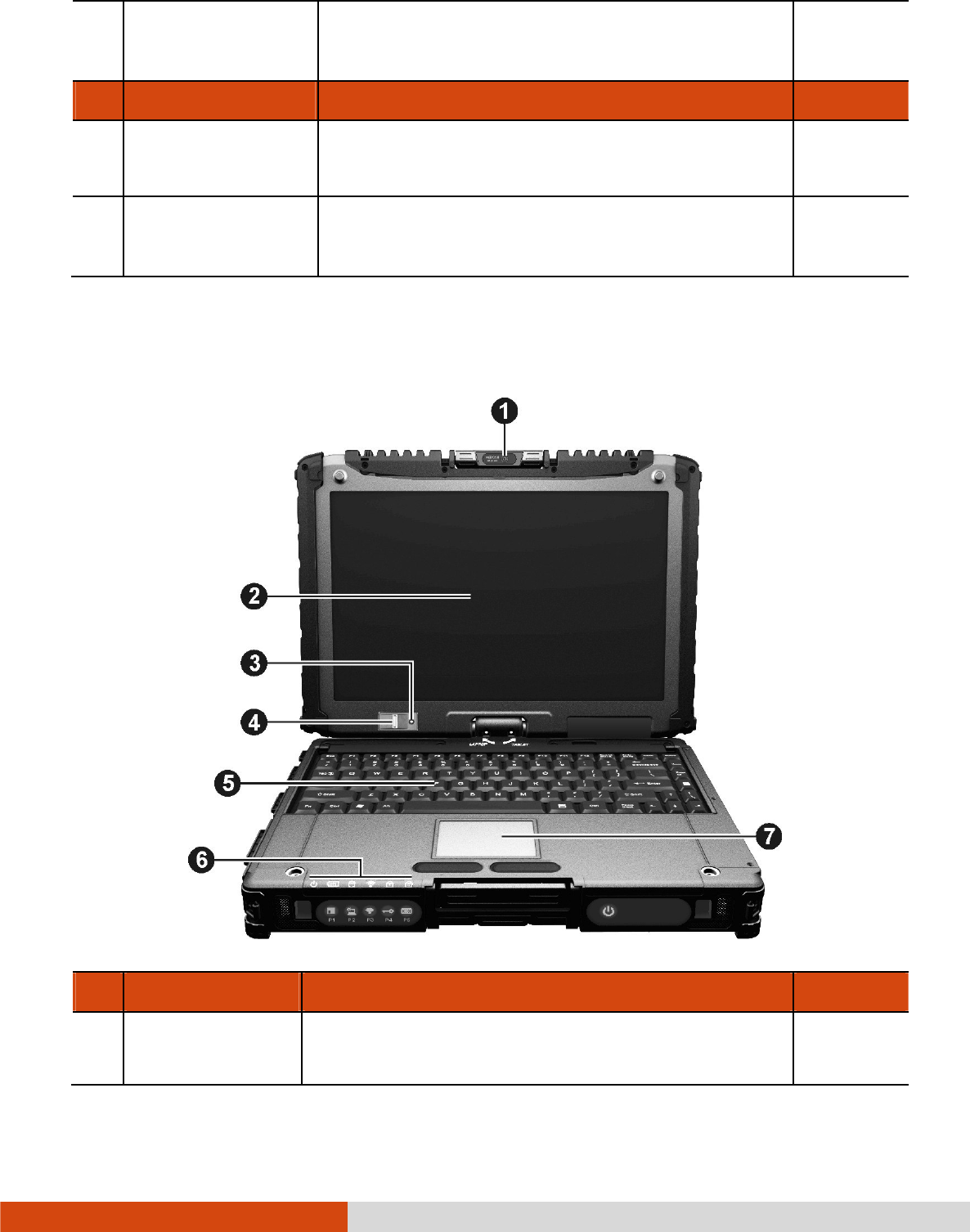
Top
TopTop
Top-
--
-open Components
open Componentsopen Components
open Components
Ref
RefRef
Ref
Com
ComCom
Component
ponentponent
ponent
Description
DescriptionDescription
Description
See Also
See AlsoSee Also
See Also
Camera Lens
Camera LensCamera Lens
Camera Lens
Allows you to use your computer’s camera
function. The lens supports 2 MP (mega pixel).
P. 6-22
1-14 Getting Started
Ref
RefRef
Ref
Com
ComCom
Component
ponentponent
ponent
Description
DescriptionDescription
Description
See Also
See AlsoSee Also
See Also
It can be rotated.
Touchscreen
TouchscreenTouchscreen
Touchscreen
Displays and receives information for the
computer.
P. 2-10
Light Sensor
Light SensorLight Sensor
Light Sensor
Detects the surrounding lighting condition for
automatic adjustment of the LCD brightness and
optional keyboard backlight.
Fingerprint
Fingerprint Fingerprint
Fingerprint
Scanner
Scanner Scanner
Scanner
(optional)
Uses fingerprint verification to protect your
computer against unauthorized access.
P. 2-27
Keyboard
KeyboardKeyboard
Keyboard
Serves as the data input device. P. 2-2
Touchpad
TouchpadTouchpad
Touchpad
Serves as the pointing device. P. 2-7
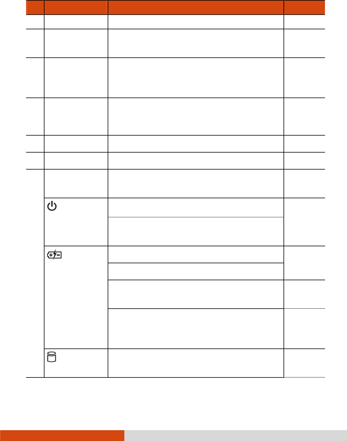
Indicators
IndicatorsIndicators
Indicators
Show the current status of the computer’s
devices.
Power
PowerPower
Power
Lights green when the computer is turned on. P. 1-7
Lights yellow when the computer is in Sleep
mode.
Battery
Battery Battery
Battery
Charge
ChargeCharge
Charge
Lights green when the battery is fully charged. P. 3-3
Lights yellow when the battery is being charged.
Blinks yellow when the battery’s capacity is below
10%.
P. 3-6
Blinks green and yellow by turns to indicate
charging is suspended because the battery’s
temperature is either too high or too low.
Hard Disk
Hard Disk Hard Disk
Hard Disk
Drive In
Drive InDrive In
Drive In-
--
-Use
UseUse
Use
Lights green when the computer is accessing the
hard disk drive.
Getting Started 1-15
Ref
RefRef
Ref
Com
ComCom
Component
ponentponent
ponent
Description
DescriptionDescription
Description
See Also
See AlsoSee Also
See Also
Blinks red when the optional hard disk drive heater
is on for low temperature operation.
P. 8-9
RF
RFRF
RF Lights when the radio frequency is on.
Num Lock
Num LockNum Lock
Num Lock Lights when Num Lock is on. P. 2-3
Caps Lock
Caps LockCaps Lock
Caps Lock Lights when Caps Lock is on. P. 2-2
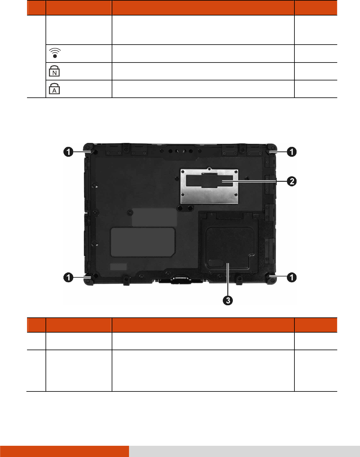
Bottom Components
Bottom ComponentsBottom Components
Bottom Components
Ref
RefRef
Ref
Component
ComponentComponent
Component
Description
DescriptionDescription
Description
See Also
See AlsoSee Also
See Also
Strap Holder
Strap HolderStrap Holder
Strap Holder
Four bottom hooks hold the handgrip strap. P. 1-18
Docking
Docking Docking
Docking
Connector
ConnectorConnector
Connector
Inside is the docking connector for connecting an
office dock or vehicle dock (purchased
separately).

1-16 Getting Started
Memory Slots
Memory SlotsMemory Slots
Memory Slots
Inside are the memory slots for expanding the
memory size of your computer.
P. 4-13
SIM Card Slot
SIM Card Slot SIM Card Slot
SIM Card Slot
(optional)
Inside is the SIM card slot. P. 2-23

Getting Started 1-17
Using the Accessories
Using the AccessoriesUsing the Accessories
Using the Accessories
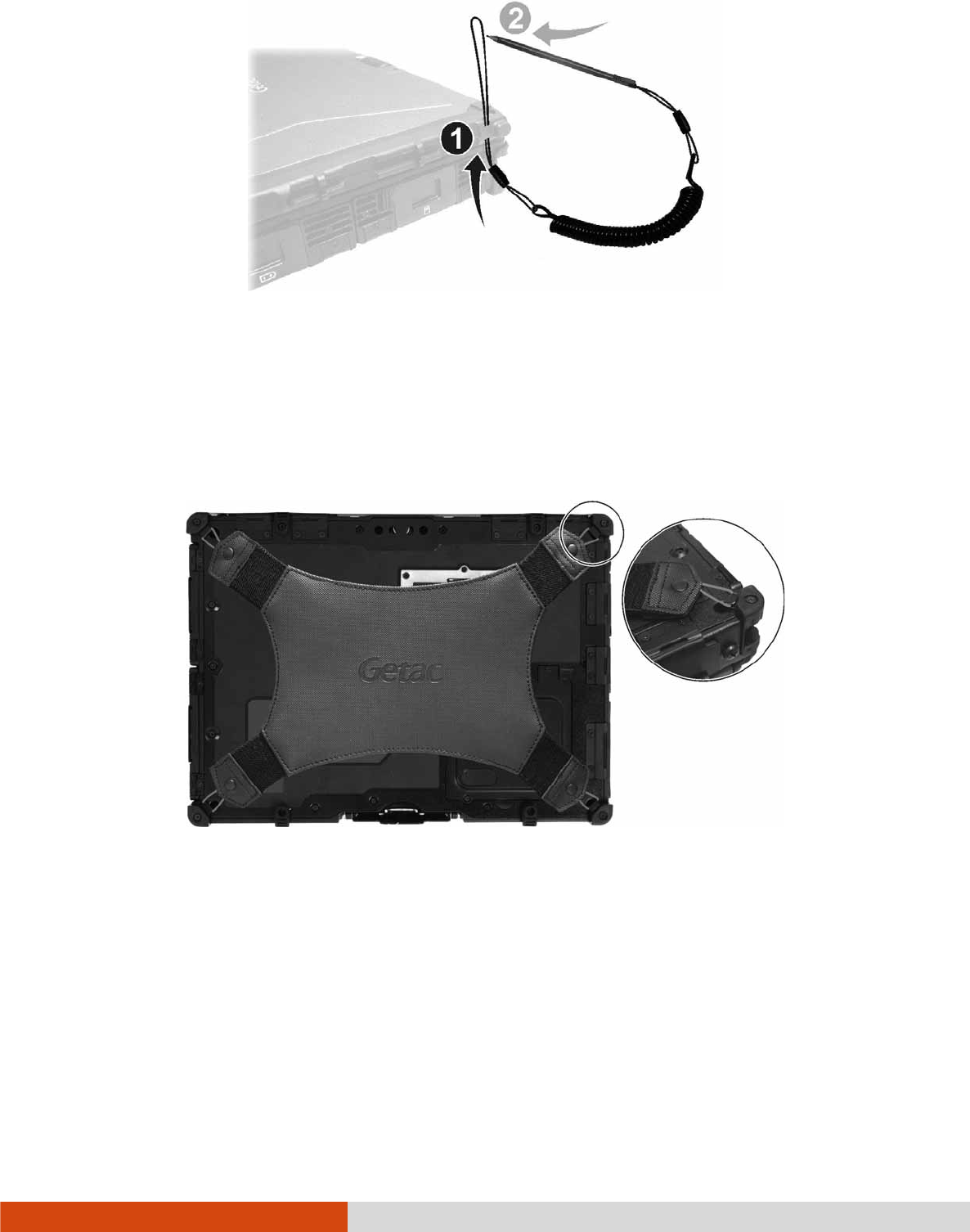
Using the Tether
Using the TetherUsing the Tether
Using the Tether
A tether is provided for attaching the stylus to your computer.
1. Insert one of the tether’s loop ends through the hole of the stylus (as indicated
by below). Then, insert the other end through the first loop (as indicated
by below) and pull it tight.
2. Insert the other loop end to the tether hole on the computer (as indicated by
below). Then, insert the stylus end through the loop (as indicated by
below) and pull it tight.
1-18 Getting Started
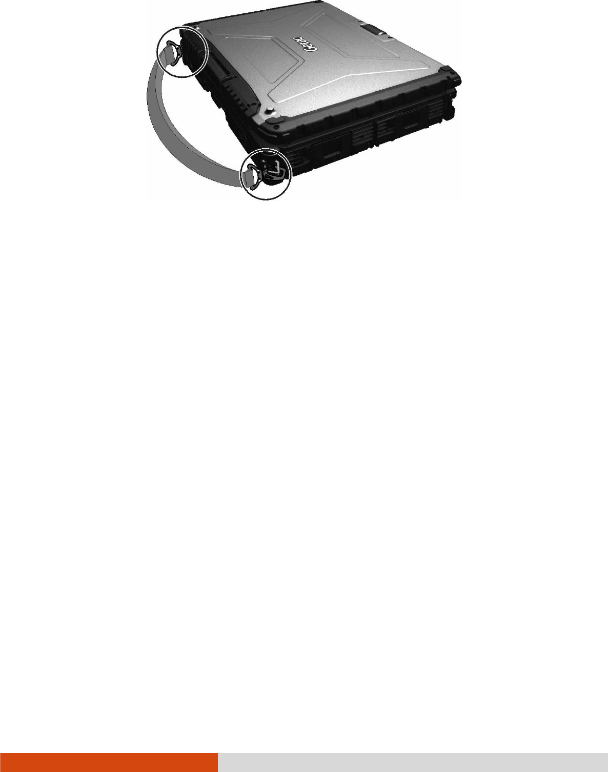
Attaching the Handgrip Strap
Attaching the Handgrip StrapAttaching the Handgrip Strap
Attaching the Handgrip Strap
To use the handgrip strap, attach its four loops to the four bottom hooks on your
computer. Make sure the loops are securely hooked.
When you need to operate and hold your computer at the same time, insert your
hand through the strap for a firm grip.
Attaching the Shoulder Strap
Attaching the Shoulder StrapAttaching the Shoulder Strap
Attaching the Shoulder Strap
To use the shoulder strap, secure the snap hooks to the two buckles on your computer.
(Select models have four buckles for different positioning of the strap.)
Getting Started 1-19
CAUTION:
The strap has been designed to carry only the weight of the computer.
Therefore, be sure that the strap does not carry a weight that exceeds the
weight of the computer. The strap may accidentally come loose from the
computer.
Do not use a strap that is damaged or about to tear.

Operating Your Computer 2-1
Chapter 2
Chapter 2Chapter 2
Chapter 2
Operating Your Computer
Operating Your ComputerOperating Your Computer
Operating Your Computer
This chapter provides information about the use of the computer.
If you are new to computers, reading this chapter will help you learn the operating
basics. If you are already a computer user, you may choose to read only the parts
containing information unique to your computer.
CAUTION:
Do not expose your skin to the computer when operating it in a very hot or cold
environment.
The computer can get uncomfortably warm when you use it in high
temperatures. As a safety precaution in such a circumstance, do not place the
computer on your lap or touch it with your bare hands for extended periods of
time. Prolonged body contact can cause discomfort and potentially a burn.

2-2 Operating Your Computer
Using the Internal Keyboard
Using the Internal KeyboardUsing the Internal Keyboard
Using the Internal Keyboard
Your keyboard has all the standard functions of a full-sized computer keyboard plus
an Fn
FnFn
Fn key added for specific functions.
The standard functions of the keyboard can be further divided into four major categories:
Typewriter keys
Cursor-control keys
Numeric keys
Function keys
Typewriter Keys
Typewriter KeysTypewriter Keys
Typewriter Keys
Typewriter keys are similar to the keys on a typewriter. Several keys are added
such as the Ctrl
CtrlCtrl
Ctrl, Alt
AltAlt
Alt, Esc
EscEsc
Esc, and lock keys for special purposes. When the lock keys
(Caps Lock
aps Lockaps Lock
aps Lock and Num Lk
Num LkNum Lk
Num Lk) are pressed, their corresponding indicators light up.
The Control (Ctrl
CtrlCtrl
Ctrl) / Alternate (Alt
AltAlt
Alt) key is normally used in combination with other
keys for program-specific functions. The Escape (Esc
EscEsc
Esc) key is usually used for
stopping a process. Examples are exiting a program and canceling a command. The
function depends on the program you are using.
Cursor
CursorCursor
Cursor-
--
-Control Keys
Control KeysControl Keys
Control Keys
Cursor-control keys are generally used for moving and editing purposes.
NOTE: The word “cursor” refers to the indicator on the screen that lets you know
exactly where on your screen anything you type will appear. It can take the form of
a vertical or horizontal line, a block, or one of many other shapes.
Operating Your Computer 2-3
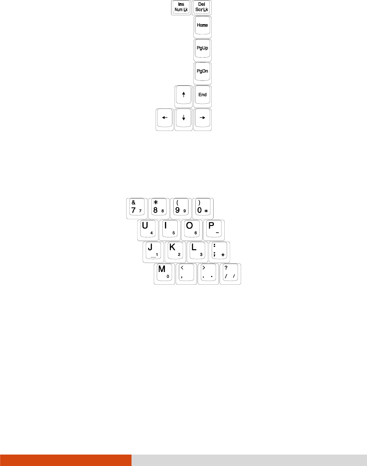
Numeric Keypad
Numeric KeypadNumeric Keypad
Numeric Keypad
A 15-key numeric keypad is embedded in the typewriter keys as shown next:
Numeric keys facilitate entering of numbers and calculations. When Num Lock is on,
the numeric keys are activated; meaning you can use these keys to enter numerals.
NOTE:
When the numeric keypad is activated and you need to type the English letter
in the keypad area, you can turn Num Lock off or you can press Fn
FnFn
Fn and then
the letter without turning Num Lock off.
Some software may not be able to use the numeric keypad on the computer. If
so, use the numeric keypad on an external keyboard instead.
2-4 Operating Your Computer
Function Keys
Function KeysFunction Keys
Function Keys
On the top row of the keys are the function keys: F1 to F12. Function keys are
multi-purpose keys that perform functions defined by individual programs.
Fn Key
Fn KeyFn Key
Fn Key
The Fn key, at the lower left corner of the keyboard, is used with another key
to perform the alternative function of a key. The letter “Fn” and the alternative functions
are identified by the color of blue on the keytop. To perform a desired function,
first press and hold Fn, then press the other key.
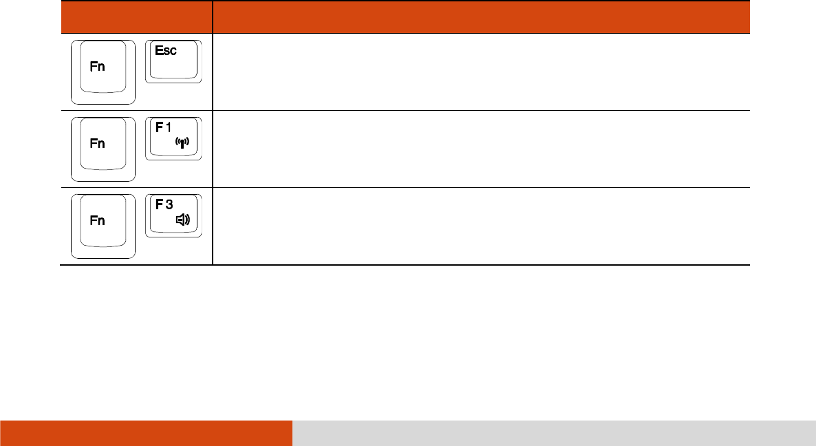
Hot Keys
Hot KeysHot Keys
Hot Keys
Hot keys refer to a combination of keys that can be pressed any time to activate
special functions of the computer. Most hot keys operate in a cyclic way. Each time
a hot key combination is pressed, it shifts the corresponding function to the other
or next choice.
You can easily identify the hot keys with the icons imprinted on the keytop. The
hot keys are described next.
Key
KeyKey
Key
Description
DescriptionDescription
Description
Switches the keyboard backlight on and off (optional).
Switches the wireless radio on and off.
Decreases the sound volume.
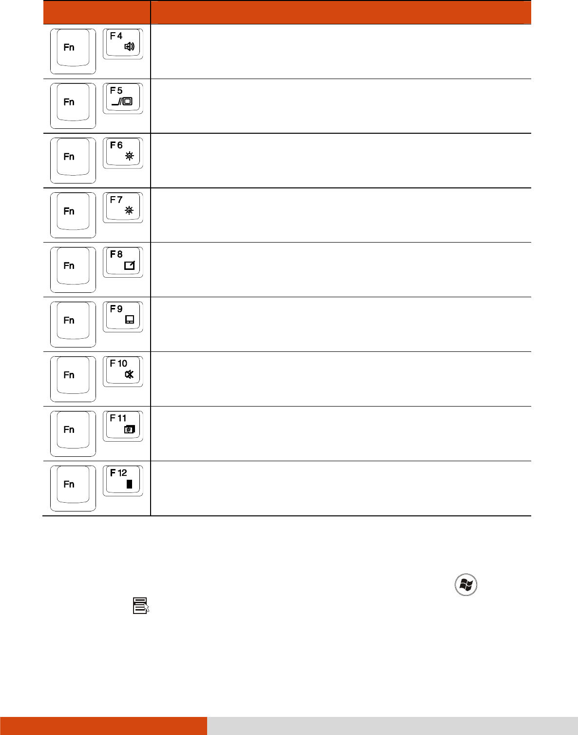
Operating Your Computer 2-5
Key
KeyKey
Key
Description
DescriptionDescription
Description
Increases the sound volume.
Switches the display output when external devices are
connected.
Decreases the LCD brightness (20 levels).
Increases the LCD brightness (20 levels).
Switches the touchscreen on and off (option).
Switches the touchpad on and off.
Switches the system sound output off (mute) and on.
Switches LCD backlight on and off.
Serves as the sleep button that you can define with Windows’
Power Options
Power OptionsPower Options
Power Options. (See the “Power Management” in Chapter 3.)
Windows Keys
Windows KeysWindows Keys
Windows Keys
The keyboard has two keys that perform Windows-specific functions: Windows
Logo key and Application key.

2-6 Operating Your Computer
The Windows Logo key opens the Start
StartStart
Start menu and performs software-specific
functions when used in combination with other keys. The Application key usually
has the same effect as a right mouse click. (See your Windows manual for more
information.)
Operating Your Computer 2-7
Using the Touchpad
Using the TouchpadUsing the Touchpad
Using the Touchpad
CAUTION: Do not use a sharp object such as a pen on the touchpad. Doing so
may damage the touchpad surface.
NOTE: For optimal performance of the touchpad, keep your fingers and the pads
clean and dry. When tapping on the pad, tap lightly. Do not use excessive force.
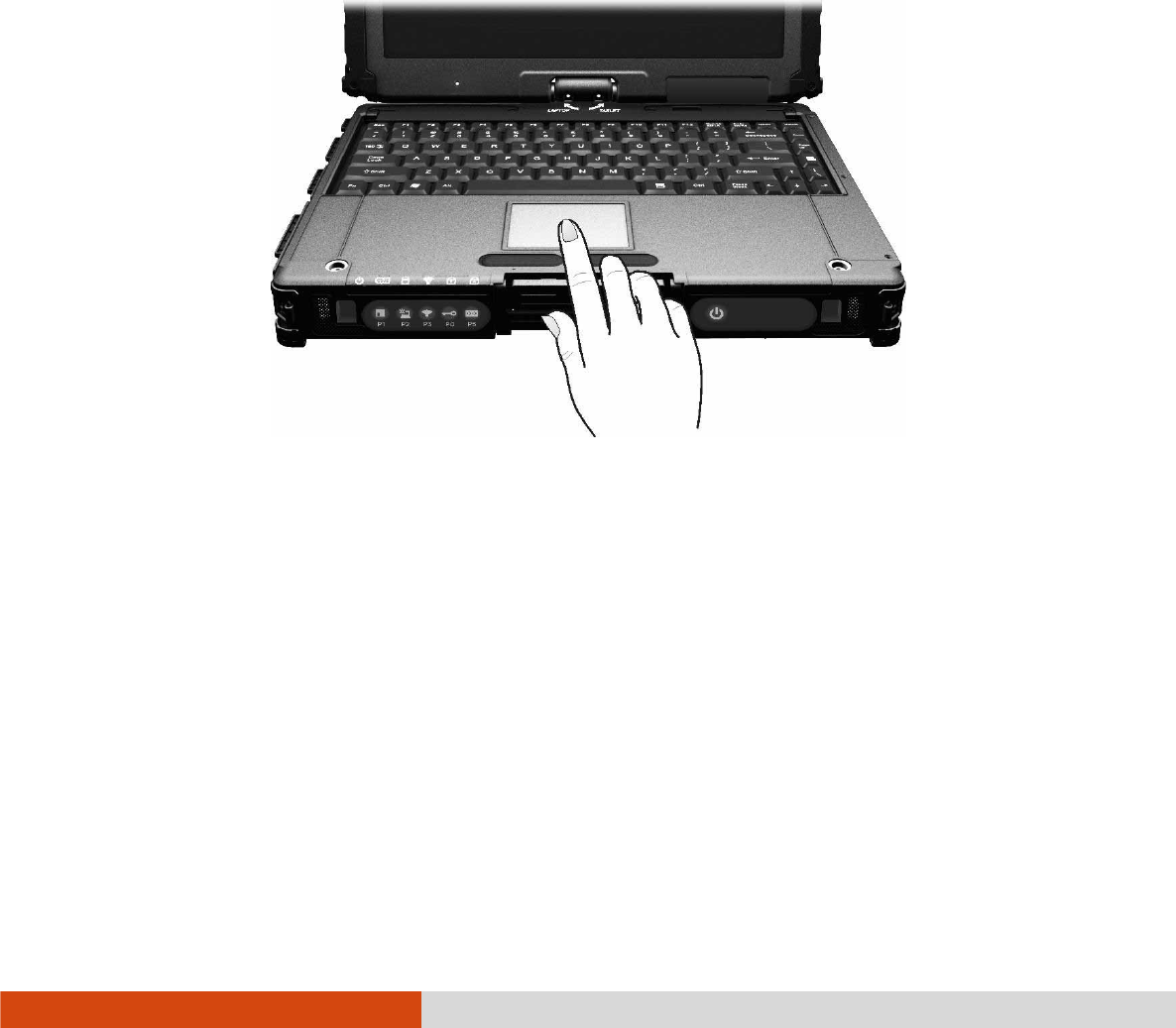
The touchpad is a pointing device that allows you to communicate with the computer
by controlling the location of the pointer on the screen and making selection with
the buttons.
The touchpad consists of a rectangular pad (work surface) and a left and right
buttons. To use the touchpad, place your forefinger or thumb on the pad. The
rectangular pad acts like a miniature duplicate of your display. As you slide your
fingertip across the pad, the pointer (also called cursor) on the screen moves
accordingly. When your finger reaches
the edge of the pad, simply relocate yourself by lifting the finger and placing it
on the other side of the pad.
Here are some common terms that you should know when using the touchpad:

2-8 Operating Your Computer
Term
TermTerm
Term
Action
ActionAction
Action
Point Move your finger on the pad until the cursor points to the selection
on the screen.
Click Press and release the left button.
–or–
Tap gently anywhere on the pad.
Double-click Press and release the left button twice in quick succession.
–or–
Tap twice on the pad rapidly.
Drag and drop Press and hold the left button, then move your finger until you
reach your destination (drag). Finally, release the button (drop)
when you finish dragging your selection to the destination. The
object will drop into the new location.
–or–
Gently tap twice on the pad and on the second tap, keep your
finger in contact with the pad. Then, move your finger across
the pad to drag the selected object to your destination. When
you lift your finger from the pad, the selected object will drop
into place.
Scroll To scroll is to move up and down or left and right in the working
area on the screen.
To move vertically, place your finger on the right or left edge
of the pad and slide your finger up and down along the edge.
To move horizontally, place your finger on the top or bottom edge
of the pad and slide your finger left and right.
This function works only after you install the touchpad driver
supplied with the computer and it may not work for all applications.
TABLE NOTE:
TABLE NOTE:TABLE NOTE:
TABLE NOTE: If you swap the left and right buttons, “tapping” on the touchpad
as
an alternative method of pressing the left button will no longer be valid.

Operating Your Computer 2-9
Configuring the Touchpad
Configuring the TouchpadConfiguring the Touchpad
Configuring the Touchpad
You may want to configure the touchpad to suit your needs. For example, if you
are a left-handed user, you can swap the two buttons so that you can use the
right button as the left button and vice versa. You can also change the size of
the on-screen pointer, the speed of the pointer, and so on.
To configure the touchpad, go to Control Panel
Control PanelControl Panel
Control Panel Mouse Properties
Mouse PropertiesMouse Properties
Mouse Properties.
2-10 Operating Your Computer
Navigating on the Screen
Navigating on the ScreenNavigating on the Screen
Navigating on the Screen
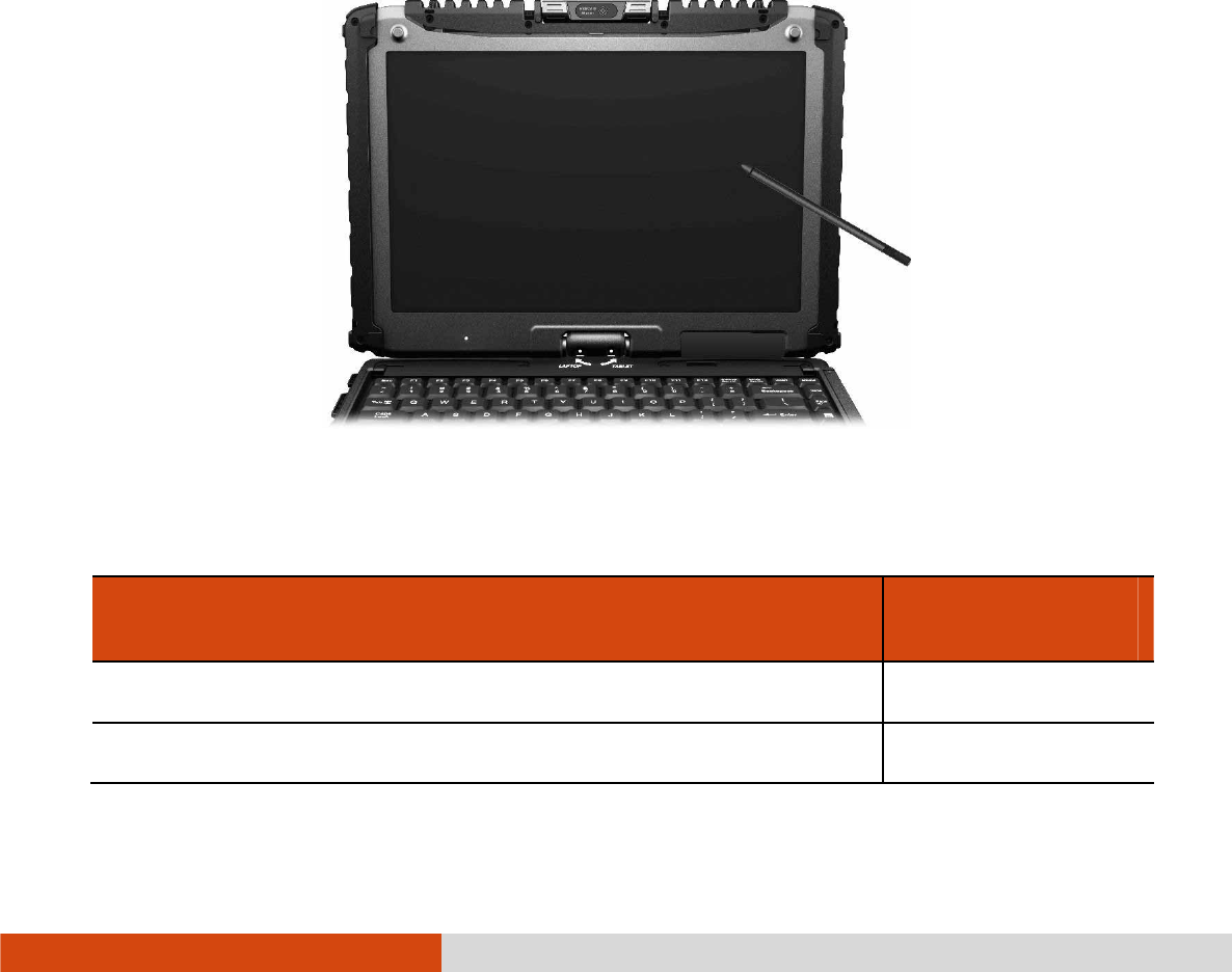
The screen of your computer is touch-sensitive. You can control the location of the
cursor/pointer on the screen using your finger or the included stylus or digitizer pen
to communicate with the computer.
CAUTION: Do not use sharp objects on the LCD display. Doing so may damage
the display surface. Use your finger or the included stylus or digitizer pen.
Using the Touchscreen
Using the TouchscreenUsing the Touchscreen
Using the Touchscreen
If your computer is equipped with the touchscreen feature, you can use your finger
or the included stylus to navigate and select objects on the screen.
The following table shows how you use the touchscreen to obtain equivalent mouse
functions.
Term/Action
Term/ActionTerm/Action
Term/Action
Equivalent Mouse
Equivalent Mouse Equivalent Mouse
Equivalent Mouse
Function
FunctionFunction
Function
Tap: Touch the screen once. Click/Point
Double-tap: Touch the screen twice rapidly. Double-click
Operating Your Computer 2-11
Term/Action
Term/ActionTerm/Action
Term/Action
Equivalent Mouse
Equivalent Mouse Equivalent Mouse
Equivalent Mouse
Function
FunctionFunction
Function
Tap and hold: Tap and hold until a popup menu appears. Right-click
Drag: Hold the stylus (or finger) on the screen and drag
across the screen until reaching your destination.
Drag
Using Multi
Using MultiUsing Multi
Using Multi-
--
-touch Gestures
touch Gesturestouch Gestures
touch Gestures
If your computer model comes with multi-touch-capable screen and Windows 7, you
can interact with your computer by placing two fingers on the screen. The movement
of the fingers across the screen creates “gestures,” which send commands to the
computer.
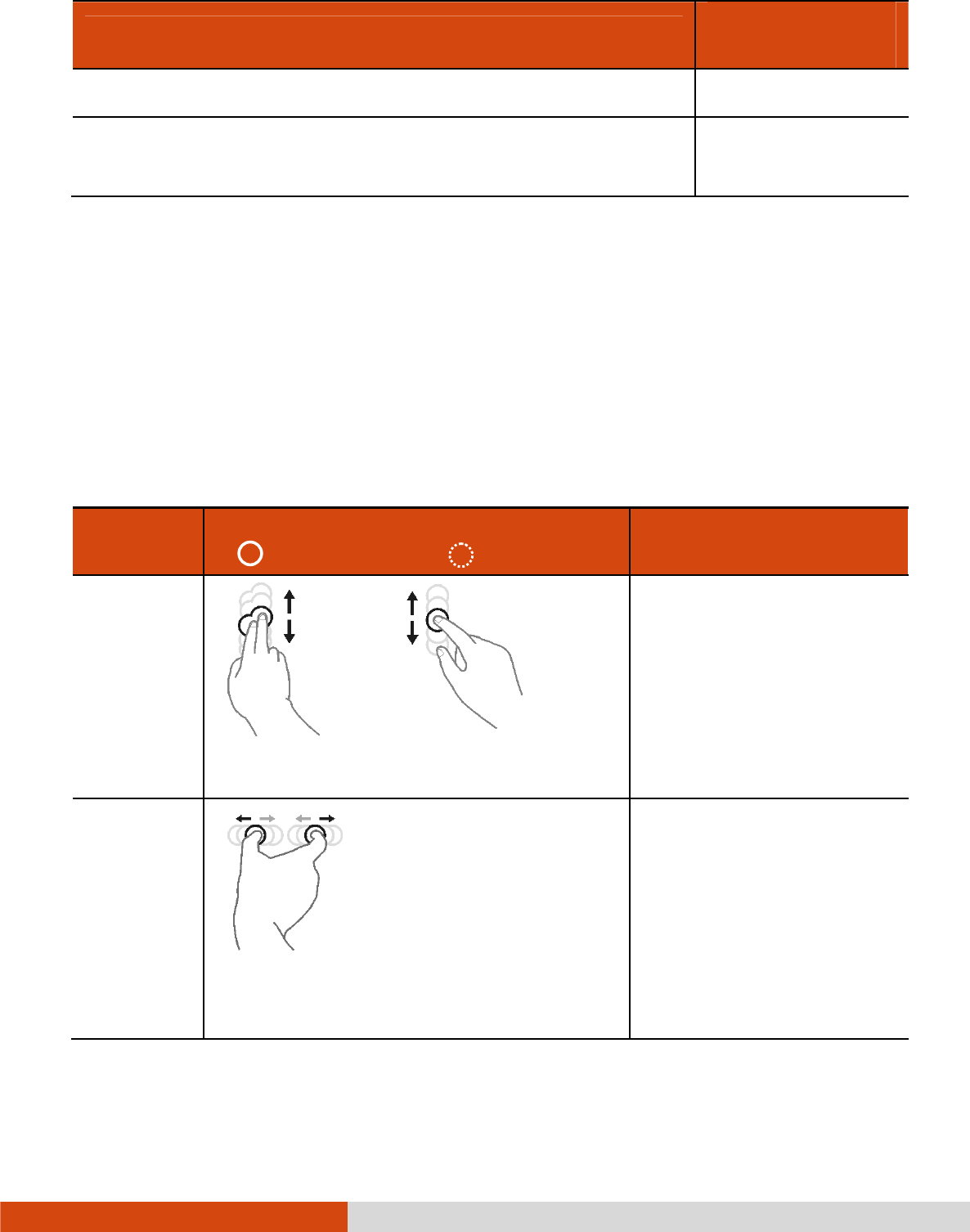
Here are the multi-touch gestures that you can use:
Gestures
GesturesGestures
Gestures
Actions
ActionsActions
Actions
( = finger down; = finger up)
( = finger down; = finger up)( = finger down; = finger up)
( = finger down; = finger up)
Descriptions
DescriptionsDescriptions
Descriptions
Pan
(Scroll)
or
Drag 1 or 2 fingers up or down.
Use panning to see
another part of a page
that has scroll bars.
Zoom
(Pinch)
Move two fingers apart/toward each
other.
Use zooming to make an
item (a photo for
example) on the screen
larger or smaller. The
gesture works in
applications that support
mouse wheel zooming.

2-12 Operating Your Computer
Gestures
GesturesGestures
Gestures
Actions
ActionsActions
Actions
( = finger down; = finger up)
( = finger down; = finger up)( = finger down; = finger up)
( = finger down; = finger up)
Descriptions
DescriptionsDescriptions
Descriptions
Rotate
or
Move two fingers in opposing directions.
-or-
Use one finger to pivot around another.
Use rotating to move a
picture or other item on
the screen in a circular
direction (clockwise or
counter-
clockwise). The gesture
works in applications that
support the specific
gesture.
Press and
Tap
Press on target and tap using a second
finger.
Use press and tap to
access the shortcut
menu.
Two-
finger Tap
Tap two fingers at the same time (where
the target is in the midpoint between the
fingers).
The function is defined by
applications that support
the specific gesture.
Operating Your Computer 2-13
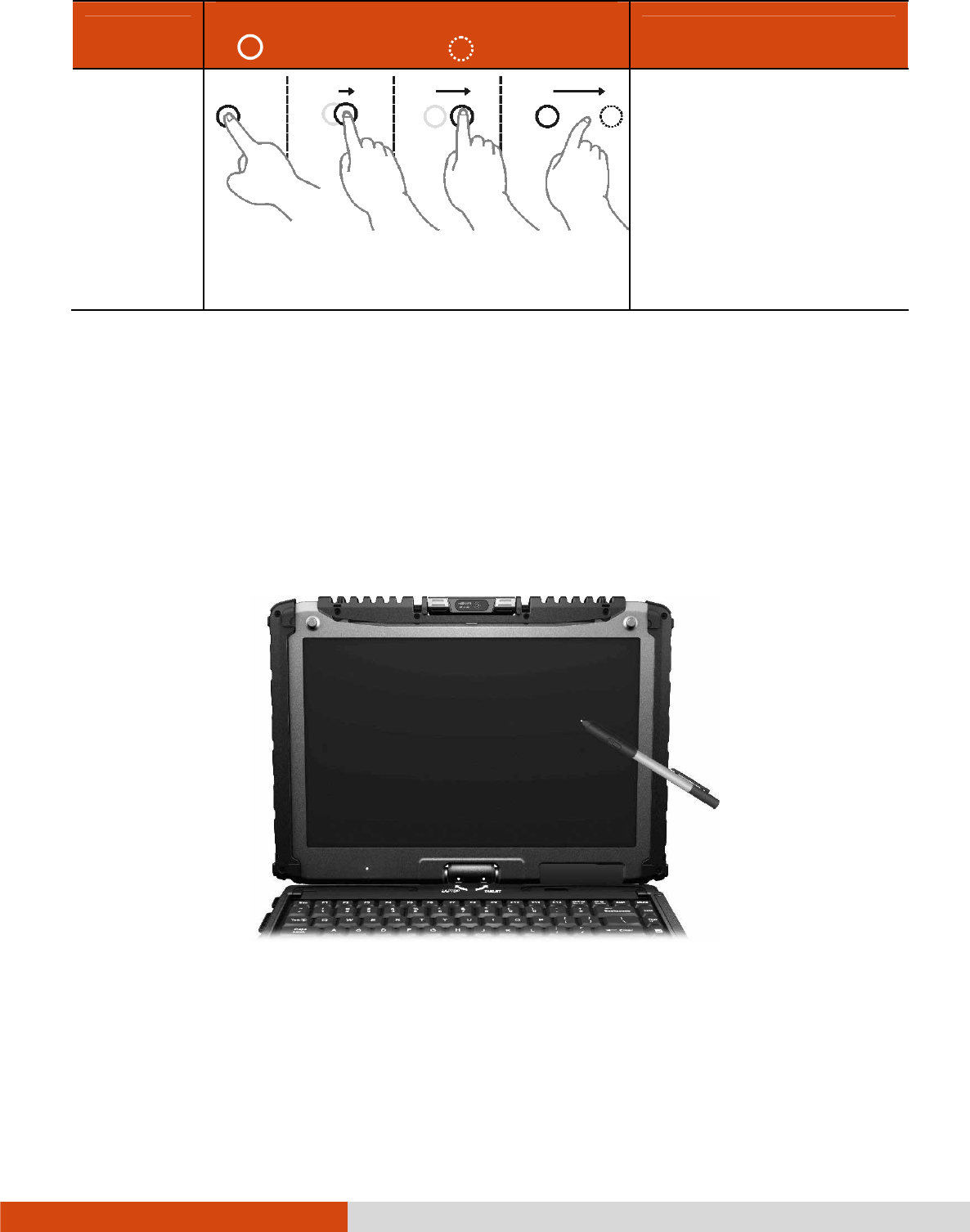
Gestures
GesturesGestures
Gestures
Actions
ActionsActions
Actions
( = finger down; = finger up)
( = finger down; = finger up)( = finger down; = finger up)
( = finger down; = finger up)
Descriptions
DescriptionsDescriptions
Descriptions
Flicks
Make quick drag gestures in the desired
direction.
Flick left or right to
navigate back and
forward in a browser and
other applications. The
gesture works in most
applications that support
back and forward.
Using the Dual Mode Display (Optional)
Using the Dual Mode Display (Optional)Using the Dual Mode Display (Optional)
Using the Dual Mode Display (Optional)
Dual mode display incorporates both touchscreen and digitizer functions.
The display is set to Touchscreen mode by default. Touchscreen mode provides all
the functionalities that an ordinary touchscreen has. When the computer receives signals
from the digitizer pen, the display automatically switches to Digitizer mode.
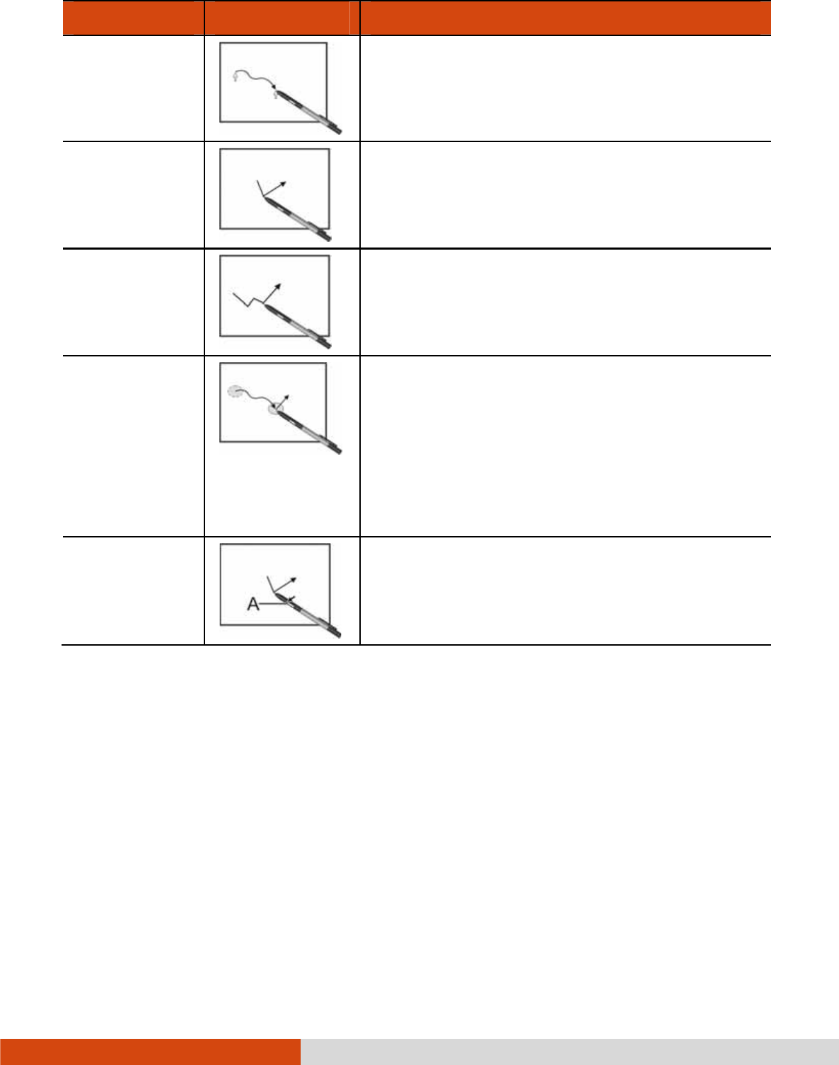
Here are some common terms that you should know when using the digitizer feature:
2-14 Operating Your Computer
Term
TermTerm
Term
Action
ActionAction
Action
Move Move the cursor pointed by the digitizer pen.
Click/Point Tap gently on the display.
Double-click Tap twice on the display rapidly.
Drag and
drop
Tap lightly on the display and move your
digitizer pen until you reach your destination
(drag). Finally, release your digitizer pen
(drop) when you finish dragging your
selection to the destination. The object will
drop into the new location.
Right-click Press and hold down the digitizer pen button
(A), then tap gently the object.
CAUTION:
When the LCD display is used alone or with an external display
simultaneously, the digitizer function cannot be used when the area of either
display is set larger than the default setting of the display resolution.
Even when only an external display is in use, the cursor will move on the
external display if you touch the surface of the LCD display with the pen or
bring the pen close to the surface of the LCD display when the digitizer driver is
active. Therefore, do not touch the LCD display when only an external display
is in use.
The active digitizer feature cannot be used in the BIOS Setup program or
when using the full screen in DOS mode.
Operating Your Computer 2-15
NOTE:
You can move the cursor by bringing the digitizer pen close to the screen,
without actually touching the screen’s surface.
Do not move the digitizer pen too quickly. If the pen moves too quickly, the
cursor may be unable to follow its movement.
If you cannot click on the edge of the screen, hold the digitizer pen
perpendicular to the display and try clicking again.
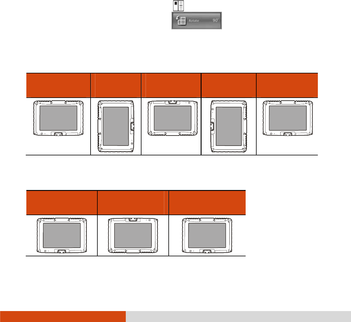
Using Landscape or Portrait View
Using Landscape or Portrait ViewUsing Landscape or Portrait View
Using Landscape or Portrait View
To rotate the display, press the button
located on the front of your computer
to open the OSD Control Panel and click . Each time this Rotate button
is clicked, the screen display rotates counter-clockwise by 90O.
For a Model without WWAN Module
For a Model without WWAN ModuleFor a Model without WWAN Module
For a Model without WWAN Module
Primary
Primary Primary
Primary
Landscape
LandscapeLandscape
Landscape
Primary
Primary Primary
Primary
Portrait
PortraitPortrait
Portrait
Secondary
Secondary Secondary
Secondary
Landscape
LandscapeLandscape
Landscape
Secondary
Secondary Secondary
Secondary
Portrait
PortraitPortrait
Portrait
Primary
Primary Primary
Primary
Landscape
LandscapeLandscape
Landscape
For a Model with WWAN Module
For a Model with WWAN ModuleFor a Model with WWAN Module
For a Model with WWAN Module
Primary
Primary Primary
Primary
La
LaLa
Landscape
ndscapendscape
ndscape
Secondary
Secondary Secondary
Secondary
Landscape
LandscapeLandscape
Landscape
Primary Landscape
Primary LandscapePrimary Landscape
Primary Landscape
Display Display
Display
Display Display
Display Display
Display

2-16 Operating Your Computer
NOTE:
If the screen display resolution has been set to 800×600 pixels, you can rotate
the display to Primary Landscape and Secondary Landscape only.
While the display is rotated:
– Do not set the display resolution larger than the resolution of the LCD
display.
– If you exit Windows, the next time Windows is started up, the operation
of the touchpad will not match the display angle for a few seconds.
– The computer’s performance will decrease slightly.
– If a video is played, the picture may not be displayed properly or the
sound may be broken up. This problem can be corrected by rotating
the display to Primary Landscape.
– The touchpad’s scroll function does not work.
The display cannot be rotated when DOS mode is set to “Full Screen.”
Operating Your Computer 2-17
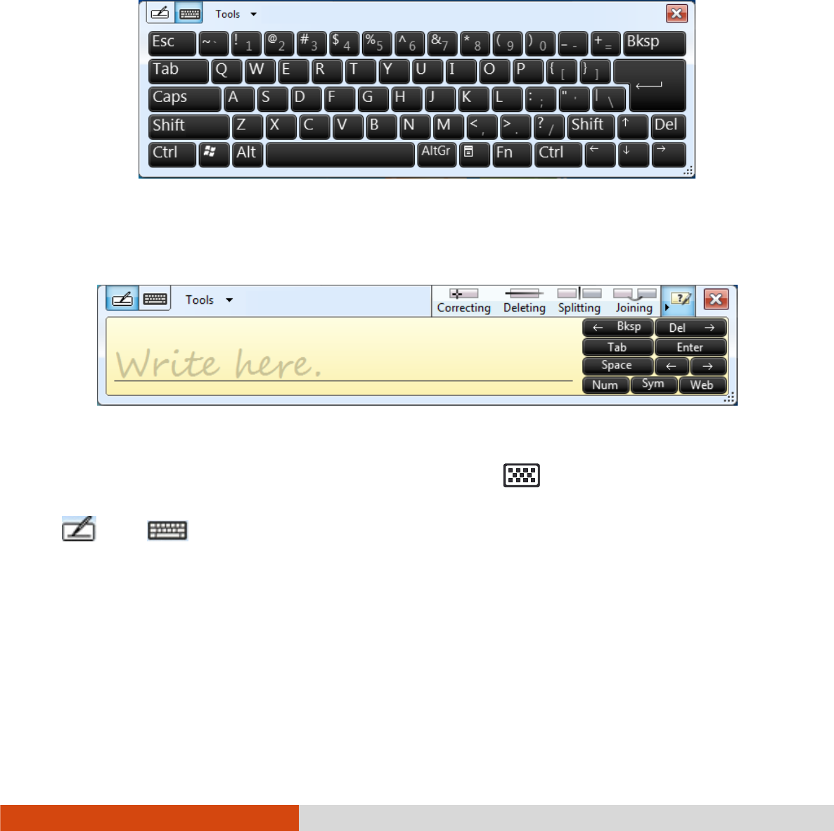
Using the Input Panel
Using the Input PanelUsing the Input Panel
Using the Input Panel
Use the Input Panel to enter text and perform various keyboard functions. There
are two types of Input Panels for you to use in Windows 7:
Touch Keyboard
Touch KeyboardTouch Keyboard
Touch Keyboard allows you to enter text by tapping the keys with your stylus,
like pressing the keys on a standard keyboard.
Writing Pad
Writing PadWriting Pad
Writing Pad allows you to write on the writing pad, like writing on a piece of
paper. Your handwriting will be converted into typed text.
To open the Input Panel, tap the Input Panel tab, which appears by default on the
left edge of the screen. (You can also press the button on the front of the
computer to open or close the Input Panel.) To switch between the two types, tap
or at the upper left corner of the Input Panel.
NOTE: For more information on using the Input Panel, see Windows’ online help.
2-18 Operating Your Computer
Using the Network Features
Using the Network FeaturesUsing the Network Features
Using the Network Features
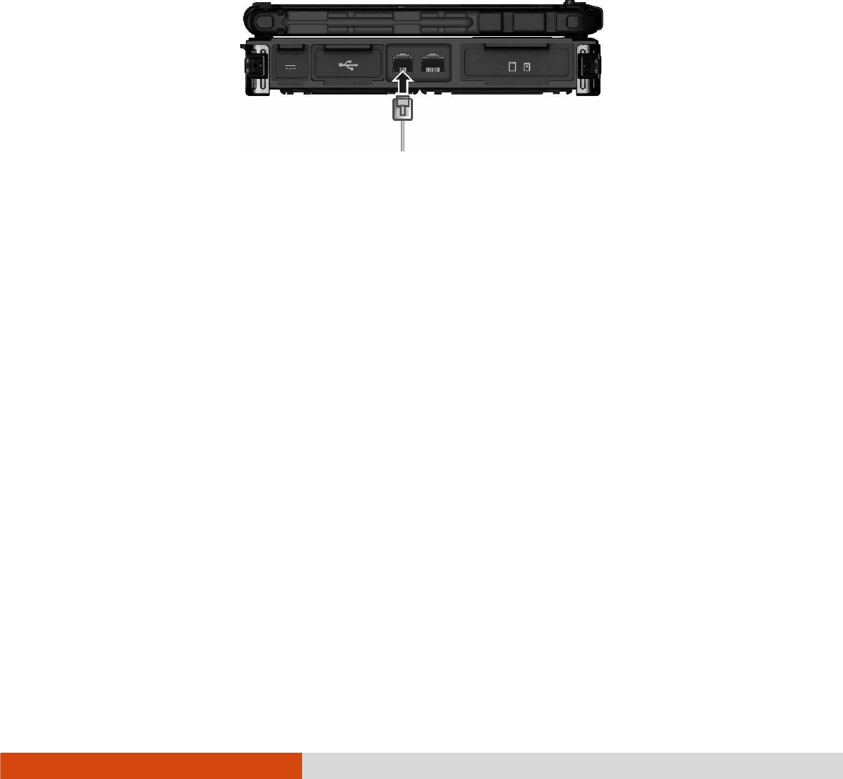
Using the Modem
Using the ModemUsing the Modem
Using the Modem
The internal 56 K fax/data modem allows you to use the telephone line to communicate
with others by fax, email, or connect to an online service or bulletin board.
To connect the telephone line to the modem, connect one end of the modem cable
to the RJ-11 connector on the computer and the other end to the phone line.
NOTE:
When using the communication software, you may have to disable power
management. Do not enter the Sleep mode when using the communication
software.
Set parameters such as modem speed (baud rate) and line type (pulse dialing
or tone dialing).
Operating Your Computer 2-19
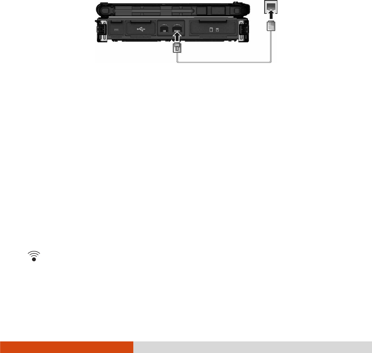
Using the LAN
Using the LANUsing the LAN
Using the LAN
The internal 10/100/1000Base-T LAN (Local Area Network) module allows you
to connect your computer to a network. It supports data transfer rate up to 1000
Mbps.
To connect the network cable to the LAN module, connect one end of the LAN
cable to the RJ-45 connector on the computer and the other end to the network
hub.
Using the Wireless LAN
Using the Wireless LANUsing the Wireless LAN
Using the Wireless LAN
The WLAN module of your computer supports IEEE 802.11a/g/n.
Turning On/Off the WLAN Radio
Turning On/Off the WLAN Radio Turning On/Off the WLAN Radio
Turning On/Off the WLAN Radio
NOTE: The FAA (Federal Aviation Agency) has deemed it unsafe to operate
wireless devices in aircraft as this may interfere with flight safety. Remember to
turn off wireless LAN when using your computer in the airplane.
FOR WIFI 5G BAND STATEMENT
The device for operation in the band 5150-5250 MHz is only for indoor use to
reduce the potential for harmful interference to co-channel mobile satellite
systems.
To turn on or off the wireless radio (including the WLAN radio), press the button
located on the front of your computer or spress Fn+F1
Fn+F1Fn+F1
Fn+F1. A small window pops
up on the screen to indicate the status.
2-20 Operating Your Computer
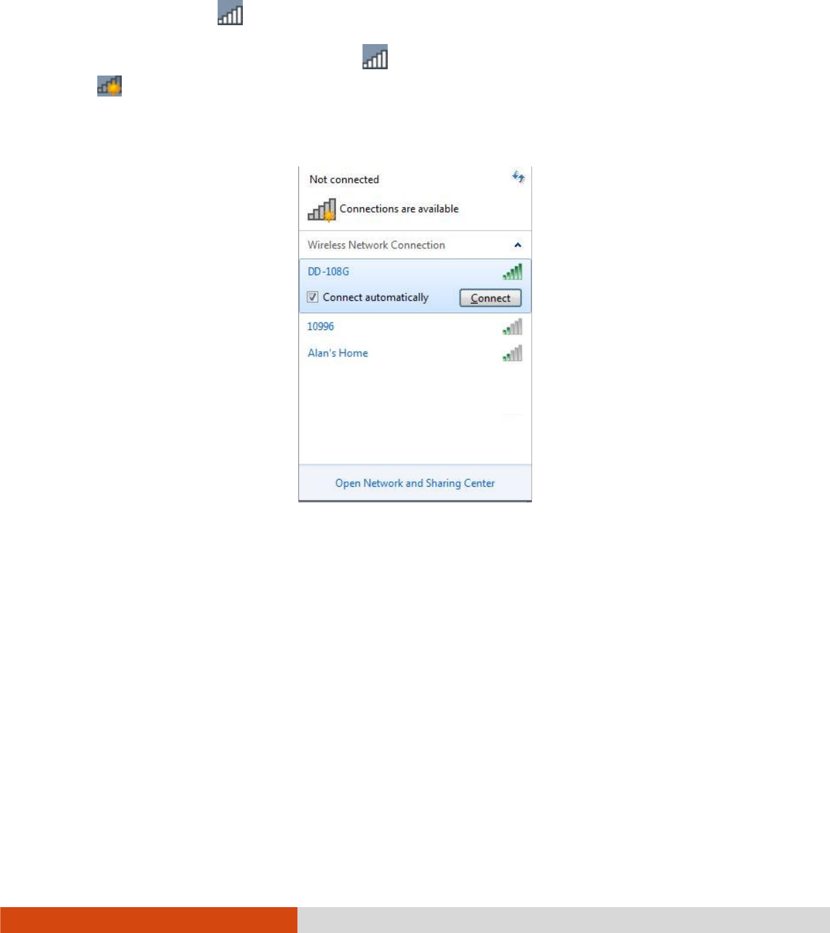
Connecting to a Wireless Network
Connecting to a Wireless NetworkConnecting to a Wireless Network
Connecting to a Wireless Network
To connect to a wireless network:
1. Make sure that the WLAN function is enabled (as described above). The Wireless
Network icon on the taskbar should appear without a red X.
2. Tap the Wireless Network icon on the taskbar. (An orange light in the icon
indicates connections are available.)
3. In the list of available wireless networks, tap a network, and then tap Connect
ConnectConnect
Connect.
4. Some networks require a network security key or passphrase. To connect to one
of those networks, ask your network administrator or Internet service provider
(ISP) for the security key or passphrase.
For more information on setting a wireless network connection, refer to Windows online
help.
NOTE: You can use Intel® PROSet Wireless to take full advantage of the WiFi
capabilities of your computer. See the Help of the utility for instructions.
Operating Your Computer 2-21
Using the Blue
Using the BlueUsing the Blue
Using the Bluetooth Feature
tooth Featuretooth Feature
tooth Feature
Your computer incorporates the Bluetooth 4.0 capability for short-range (about 50
meters) wireless communications between devices without requiring a cable
connection. With Bluetooth, data can be transmitted through walls, pockets and
briefcases as long as two devices are within range.
Turning Off/On the Bluetooth Radio
Turning Off/On the Bluetooth RadioTurning Off/On the Bluetooth Radio
Turning Off/On the Bluetooth Radio
To turn on or off the wireless radio (including the Bluetooth radio), press the button
located on the front of your computer or spress Fn+F1
Fn+F1Fn+F1
Fn+F1. A small window pops
up on the screen to indicate the status.
When the Bluetooth radio is on, the Bluetooth icon appears on the Windows
taskbar.
Connecting to another Bluetooth Device
Connecting to another Bluetooth DeviceConnecting to another Bluetooth Device
Connecting to another Bluetooth Device
1. Make sure that the Bluetooth function is enabled (as described above).
2. Make sure that the target Bluetooth device is turned on, discoverable and within
close range. (See the documentation that came with the Bluetooth device.)
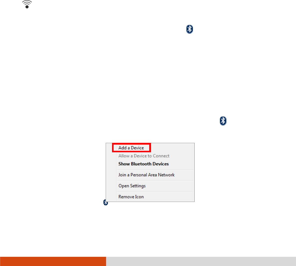
3. To search for Bluetooth devices, right click the Bluetooth icon and select Add
a Device.
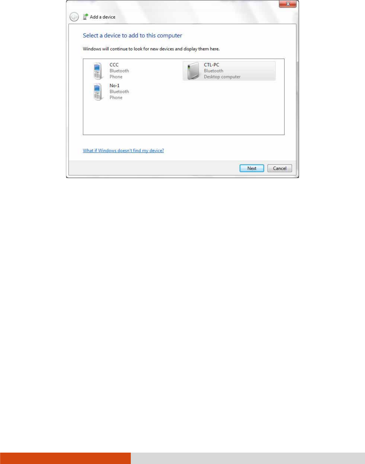
4. Select the device you want to connect from the search results.
2-22 Operating Your Computer
5. Depending on the type of Bluetooth device that you want to connect to, you
will need to enter the pertinent information.
For detailed information on using the Bluetooth feature, see Windows’ online Help.
Operating Your Computer 2-23
Using the WWAN Feature (Option
Using the WWAN Feature (OptionUsing the WWAN Feature (Option
Using the WWAN Feature (Optional)
al)al)
al)
A WWAN (Wireless Wide Area Network) uses mobile telecommunication cellular
network technologies to transfer data. The WWAN module of your computer supports
3G or 4G LTE depending on your model.
NOTE: Your computer only supports data transmission; voice transmission is not
supported.
Installing a SIM Card
Installing a SIM CardInstalling a SIM Card
Installing a SIM Card
To use the WWAN feature to connect to the Internet, you need to subscribe to the
service and acquire a SIM card from a mobile phone network service provider.
To install the SIM card, follow these steps:
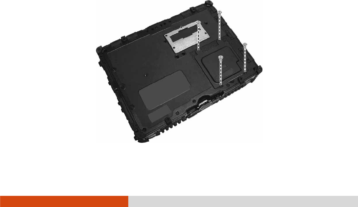
1. Turn off the computer and disconnect the AC adapter.
2. Carefully place the computer upside down.
3. Remove the four screws to open the compartment cover.
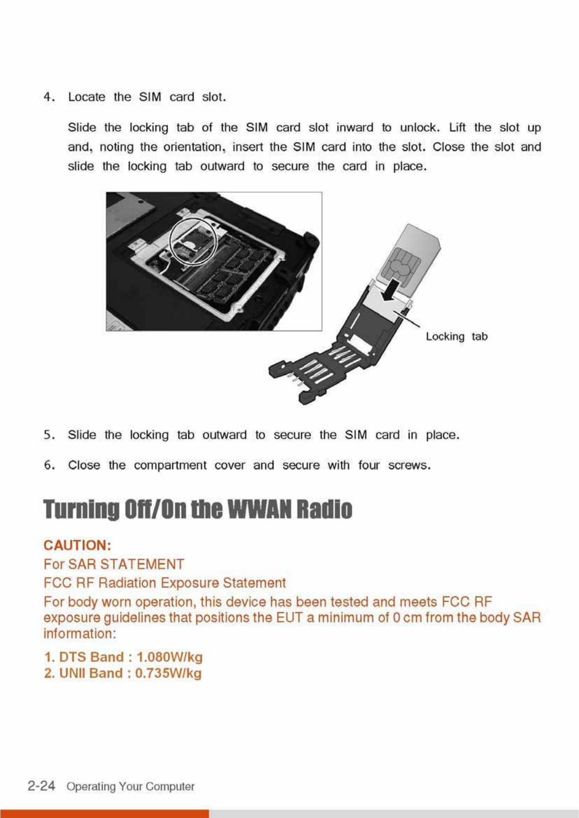
Operating Your Computer 2-25
To turn on or off the wireless radio (including the WWAN radio), press the button
located on the front of your computer. A small window pops up on the screen
to indicate the status.
Connecting to WWAN Network
Connecting to WWAN NetworkConnecting to WWAN Network
Connecting to WWAN Network
1. Make sure that the SIM card is inserted and WWAN function is enabled (as
described above).
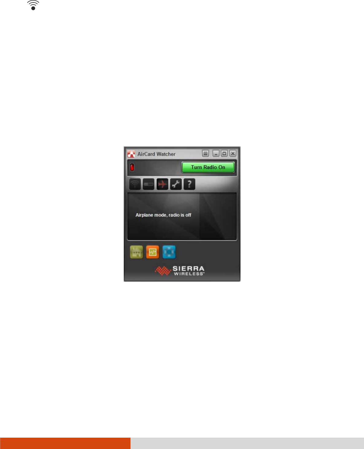
2. On Windows desktop, double-click the AirCard Watcher
AirCard WatcherAirCard Watcher
AirCard Watcher shortcut. The screen as
below appears.
3. If the radio is currently off, click Turn Radio On
Turn Radio OnTurn Radio On
Turn Radio On to turn on the radio.
4. Use AirCard Watcher to manage your broadband wireless network connections
such as:
Connect to the Internet
Configure user options
Send and receive SMS messages

2-26 Operating Your Computer
Manage profiles
Use GPS to track your position (for models having the GPS module)
NOTE: For detailed information on using AirCard Watcher, see the program’s
online help.

Operating Your Computer 2-27
Using the Fingerpri
Using the FingerpriUsing the Fingerpri
Using the Fingerprint Scanner
nt Scanner nt Scanner
nt Scanner
(Optional)
(Optional)(Optional)
(Optional)
CAUTION:
We shall not be liable for any loss or damage whatsoever resulting from your
use of the fingerprint scanner or neglect of fingerprint scanner use, or any data
loss resulting from such developments as fingerprint authentication
malfunctioning.
It is not recommended that you use the fingerprint scanner in a below-freezing
temperature. The moisture on your finger can freeze to the scanner’s metal
surface when you touch it, resulting in a failed operation.
The fingerprint scanner provides a strong authentication mechanism based on fingerprint
recognition. It features:
Website Log On
Logon to your web accounts like banks, webmail, and more with a simple swipe
of your finger.
Windows Log On
Logon to Microsoft® Windows® with a simple swipe of your finger every time
you turn on your computer or log onto your desktop.
QuickLaunch
Quickly launch all your favorite websites, open files and folders, and log in to
your accounts with a simple swipe of your finger.
KeepSafe
Protect your pictures, personal files, and folders using your fingerprint so only
you can access them.
NOTE: You can register a fingerprint only after creating a password for the
Windows user account.
2-28 Operating Your Computer
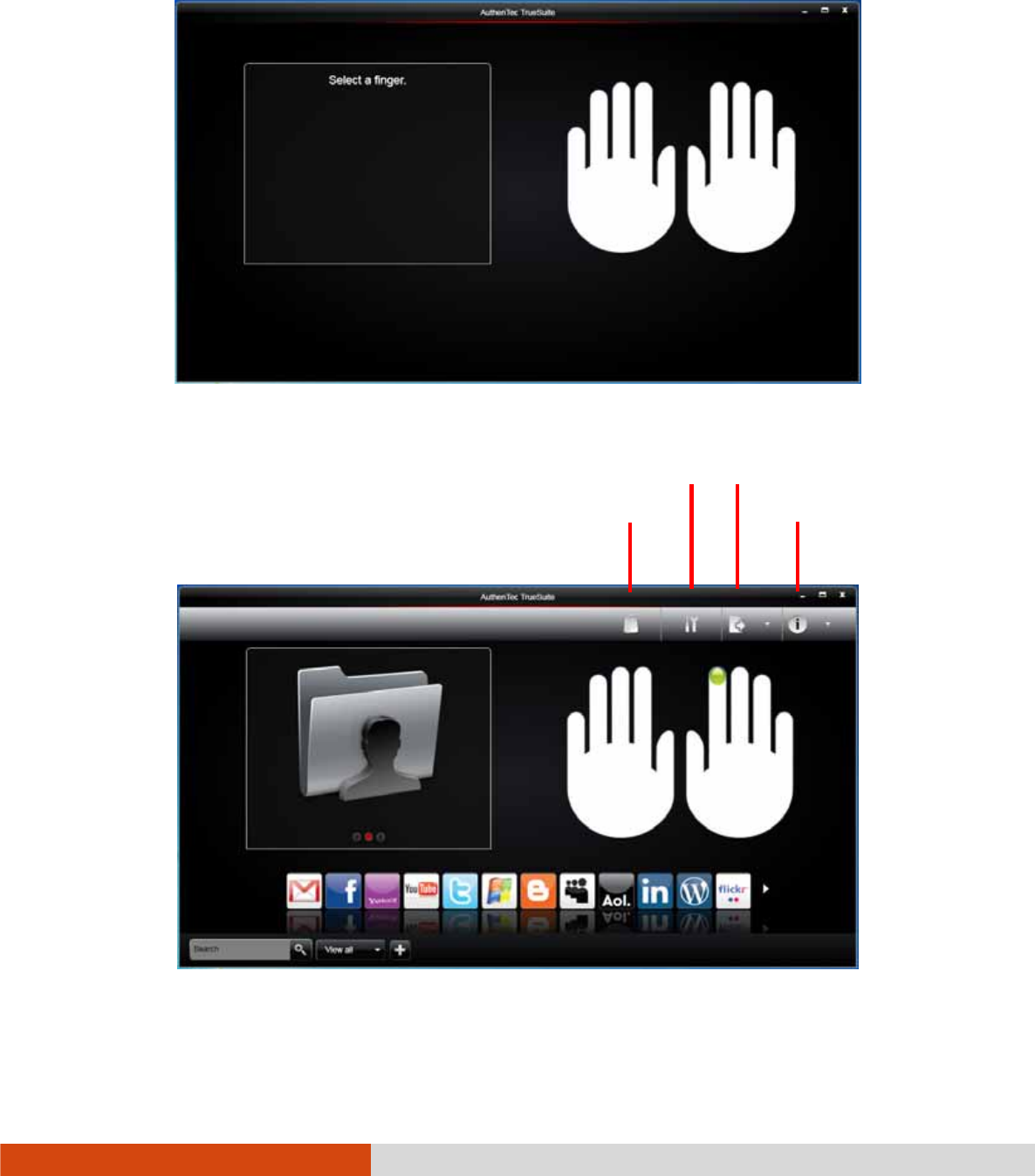
To register your fingerprint, click Start
StartStart
Start All Programs
ProgramsPrograms
Programs AuthenTe
AuthenTeAuthenTe
AuthenTec TrueSuite
c TrueSuitec TrueSuite
c TrueSuite
AuthenTec TrueSuite
AuthenTec TrueSuiteAuthenTec TrueSuite
AuthenTec TrueSuite. Click the finger you want to register and follow the onscreen
instructions to complete.
You can then use the Fingerprint Software to set up how the fingerprint authentication
works.
App Store
Settings Options
Help

Operating Your Computer 2-29
For detailed information, click
the Help button of the software.

Managing Power 3-1
Chapter 3
Chapter 3Chapter 3
Chapter 3
Managing Power
Managing PowerManaging Power
Managing Power
Your computer operates either on external AC power or on internal battery power.
This chapter tells you how you can effectively manage power. To maintain optimal
battery performance, it is important that you use the battery in the proper way.

3-2 Managing Power
AC Adapter
AC AdapterAC Adapter
AC Adapter
CAUTION:
The AC adapter is designed for use with your computer only. Connecting the
AC adapter to another device can damage the adapter.
The AC power cord supplied with your computer is for use in the country where
you purchased your computer. If you plan to go overseas with the computer,
consult your dealer for the appropriate power cord.
When you disconnect the AC adapter, disconnect from the electrical outlet first
and then from the computer. A reverse procedure may damage the AC
adapter or computer.
When unplugging the connector, always hold the plug head. Never pull on the
cord.
The AC adapter serves as a converter from AC (Alternating Current) to DC (Direct
Current) power because your computer runs on DC power, but an electrical outlet
usually provides AC power. It also charges the battery pack when connected to AC
power.
The adapter operates on any voltage in the range of 100~240 V AC.

Managing Power 3-3
Battery Pack
Battery PackBattery Pack
Battery Pack
The battery pack is the internal power source for the computer. It is rechargeable
using the AC adapter.
The operating time of a fully charged battery pack depends on how you are using
the computer. When your applications often access peripherals, you will experience
a shorter operating time.
NOTE: Care and maintenance information for the battery is provided in the
“Battery Pack” section in Chapter 7.
Charging
ChargingCharging
Charging
the Battery Pack
the Battery Packthe Battery Pack
the Battery Pack
NOTE:
Charging will not start if the battery’s temperature is below 0 °C (32 °F) or
above 40 °C (104 °F); the charging process will stop if the battery’s
temperature gets above 60 °C (140 °F). To avoid damaging the battery under
this situation, disconnect the AC adapter and wait for the battery to return to
room temperature before charging again.
During charging, do not disconnect the AC adapter before the battery has
been fully charged; otherwise you will get a prematurely charged battery.
To charge the battery pack, connect the AC adapter to the computer and an electrical
outlet. The Battery Charge Indicator ( ) on the computer glows yellow to indicate
that charging is in progress. You are advised to keep the computer power off while
the battery is being charged. When the battery is fully charged, the Battery Charge
Indicator lights green.
It takes approximately 3 hours to fully charge the Li-Ion battery pack when the
computer is off, and approximately 6 hours to fully charge the Li-Ion battery pack
when the computer is on.

3-4 Managing Power
CAUTION: After the computer has been fully recharged, do not immediately
disconnect and reconnect the AC adapter to charge it again. Doing so may
damage the battery.
NOTE: The battery level may automatically lessen due to the self-discharge
process (0.21 % per day), even when the battery pack is fully charged (100 %).
This happens no matter if the battery pack is installed in the computer.
Initializing the Battery Pack
Initializing the Battery PackInitializing the Battery Pack
Initializing the Battery Pack
You need to initialize a new battery pack before using it for the first time or when
the actual operating time of a battery pack is much less than expected. Initializing
is the process of fully charging, discharging, and then charging. It can take several
hours.
A tool called “Gauge Reset” is provided for the purpose. See “Gauge Reset” in
Chapter 6 for information on using the tool.
Checking the Battery Level
Checking the Battery Level Checking the Battery Level
Checking the Battery Level
NOTE: Any battery level indication is an estimated result. The actual operating
time can be different from the estimated time, depending on how you are using the
computer.
By Operating System
By Operating SystemBy Operating System
By Operating System
You can check the approximate battery level using the battery meter function of the
operating system. To read the battery level in Windows, click the battery icon on
the taskbar.
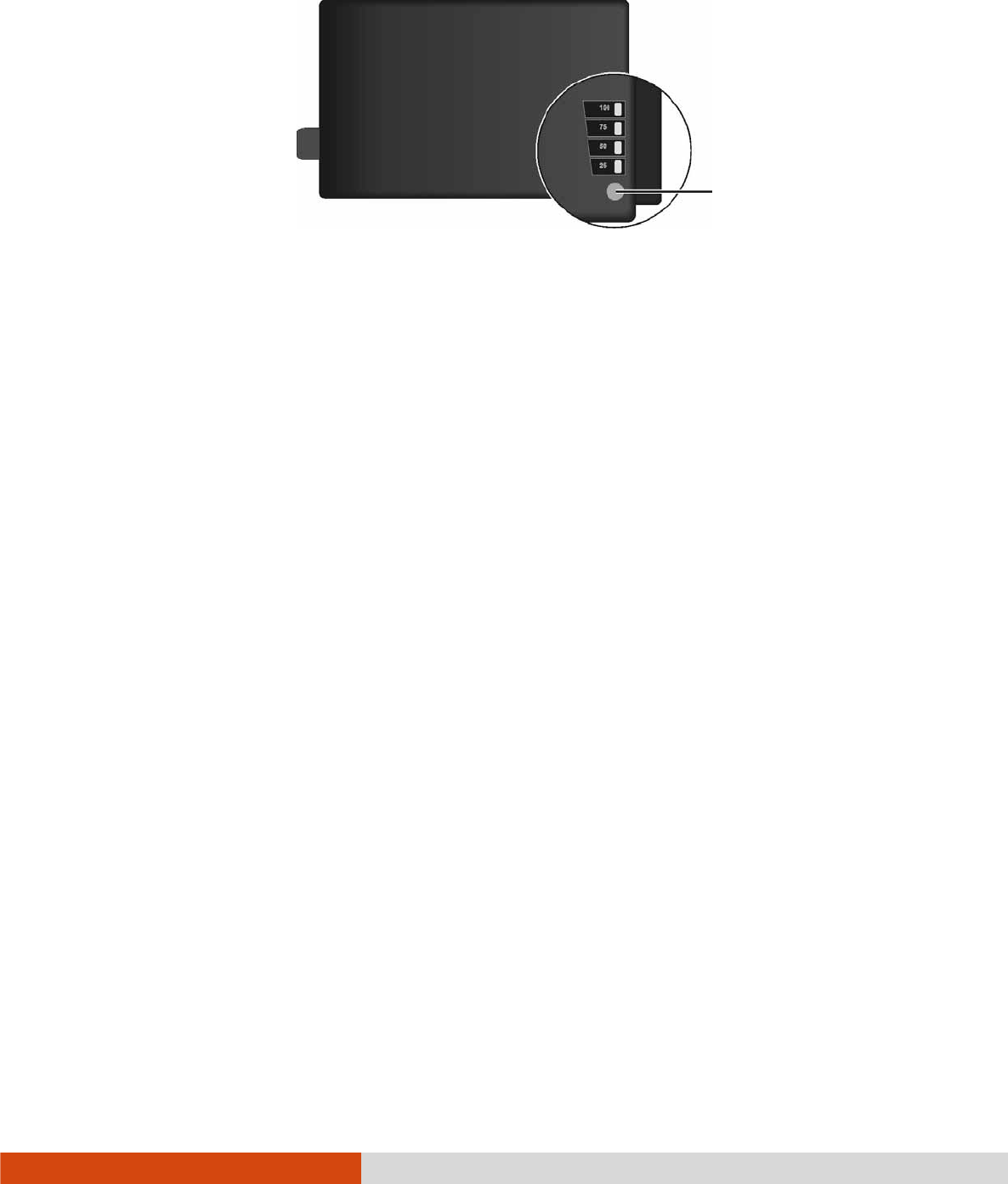
By Gas Gauge
By Gas GaugeBy Gas Gauge
By Gas Gauge
On the exterior side of the battery pack is a gas gauge for displaying the estimated
battery charge. When the battery pack is not installed in the computer and you want
Managing Power 3-5
to know the battery charge, you can press the switch with a pointed device to see
the corresponding value of indicator segment that light green.
The value of the corresponding green segment indicates the relative percentage of
the battery charge. The battery pack is fully discharged when you see no segment
glowing green.
Replacing the Battery Pack
Replacing the Battery PackReplacing the Battery Pack
Replacing the Battery Pack
CAUTION:
There is danger of explosion if the battery is incorrectly replaced. Replace the
battery only with the computer manufacturer’s optional battery packs. Discard
used batteries according to the dealer’s instructions.
Do not attempt to disassemble the battery pack.
If you often rely on battery power for a long period of time while traveling, you
may consider the purchase of an additional battery pack from your dealer and keep
it with you in a fully charged state as a backup.
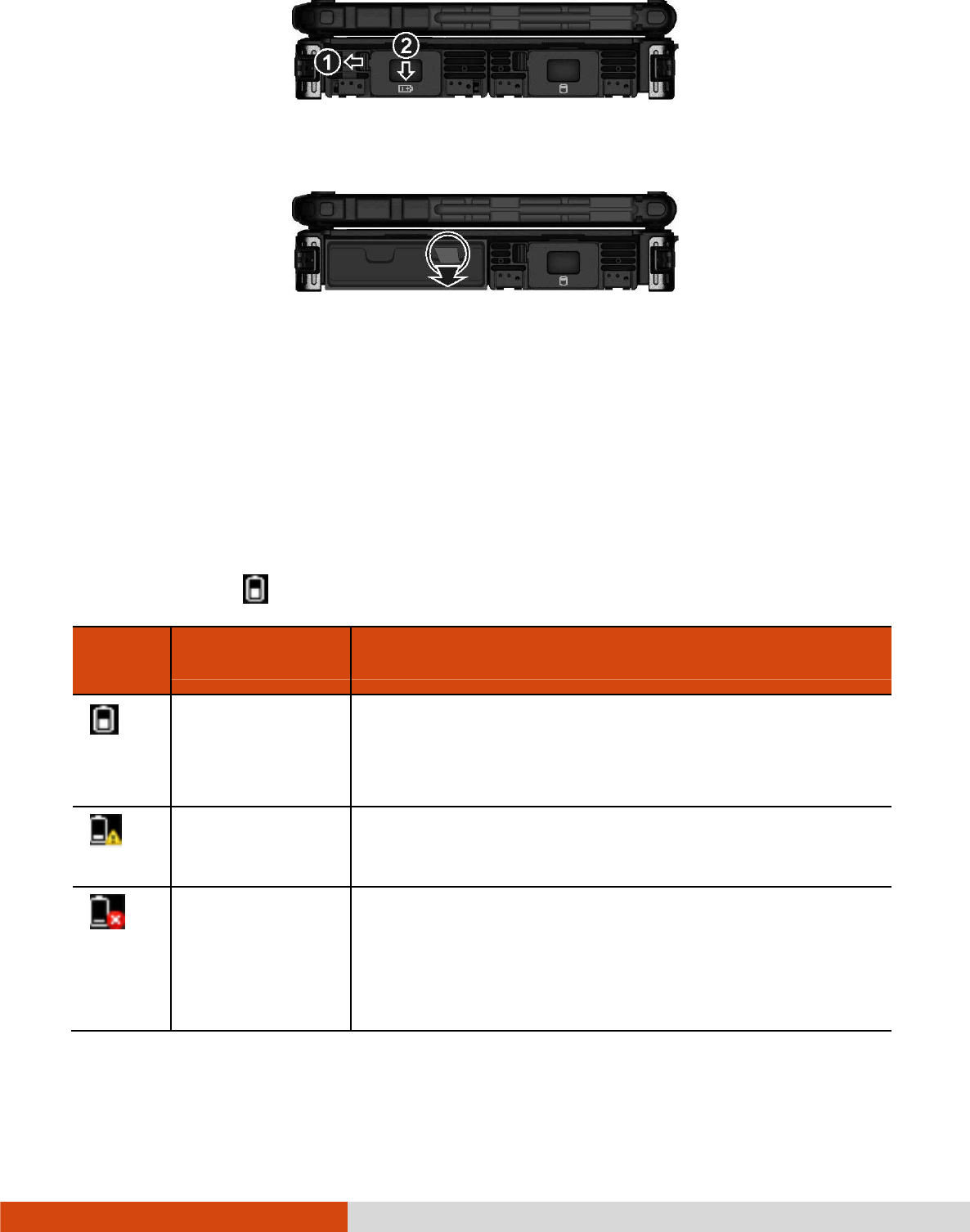
To replace the battery pack, follow these steps:
1. Make sure that the computer is not turned on or connected to AC power.
2. Locate the battery compartment on the right side of the computer.
3. Slide the door lock toward the left to unlock (). Then slide the door latch
downward to open the door ().
Switch
3-6 Managing Power
4. Pull the ribbon strip to remove the battery pack.
5. With the ribbon strip facing outward, slide the new battery pack all the way into
the slot.
6. Close the door. Make sure the door latch clicks into place. Then, slide the door
lock toward the right.
Battery Low
Battery Low Battery Low
Battery Low Signa
SignaSigna
Signals and Action
ls and Actionls and Action
ls and Actions
ss
s
The battery icon changes appearance to display the current state of the battery.
Battery
Battery Battery
Battery
Icon
IconIcon
Icon
Battery Level
Battery LevelBattery Level
Battery Level
Description
DescriptionDescription
Description
Discharging The icon shows the charge remaining in 10-percent
increments until the charge reaches the low-battery
level.
Low The battery charge has reached the low-battery level
(10% by default).
Critically low The battery charge has reached the critical battery
level (5% by default). By default, Windows will
display a notification and put your computer into
Hibernation.

Managing Power 3-7
When the battery is low, the computer’s Battery Charge Indicator ( ) also
blinks red to alert you to take actions.
Always respond to low-battery by connecting the AC adapter, placing your computer
in Hibernation mode, or turning off the computer.

3-8 Managing Power
Power Management
Power ManagementPower Management
Power Management
Your computer supports ACPI (Advanced Configuration and Power Interface) for
power management. The power management feature allows you to reduce the power
consumption for energy saving.
With an ACPI-compliant operating system such as Windows, power supply to different
computer components is controlled on an as-needed basis. This allows maximum
power conservation and performance at the same time.
In general, Windows’ power management works in this way:
What...
What...What...
What...
When...
When...When...
When...
Power to the hard disk is turned off When the hard disk has been idle for a set
period.
Power to the display is turned off When the display has been idle for a set
period.
The computer enters the Sleep mode.
The hard disk and display are turned
off and the entire system consumes
less power.
When the entire system has been idle for
a set period.
When you manually activate the mode.
The computer enters the Hibernation
mode. (See the next subsection for
more information.)
When the entire system has been idle for
a set period.
When you manually activate the mode.
For detailed information on power management, see Windows’ Help.

Managing Power 3-9
Hibernation
HibernationHibernation
Hibernation
Hibernation is a very useful feature. People frequently open many applications when
they use computers. It takes some time to get all these applications open and running,
and normally they all have to be closed before the computer can be turned off.
When you use the hibernation feature, you do not have to close the applications.
The computer stores the state of your computer to a file on the hard disk and then
shuts down. The next time you turn on your computer, you return to exactly where
you left off.

3-10 Managing Power
Power
PowerPower
Power-
--
-Saving Tips
Saving TipsSaving Tips
Saving Tips
Aside from enabling your computer’s power saving mode (see previous section),
you can do your part to maximize the battery’s operating time by following these
suggestions.
Enter power saving mode when using battery power.
Do not disable automatic power management features.
Decrease the LCD brightness to the lowest comfortable level.
Shorten the length of time before Windows turn off the display.
Many USB devices use power just by being connected. If you use a USB mouse,
you can save power by disconnecting the mouse and using the touchpad. If
you use a USB flash drive, unplug it when you are not using it.
Remove the card (such as PC card, ExpressCard, and Smart Card) if not using
it.
Turn off the wireless radio if you are not using the wireless module (such as
WLAN, Bluetooth, or WWAN).
Turn off the computer when you are not using it.

Expanding Your Computer 4-1
Chapter 4
Chapter 4Chapter 4
Chapter 4
Expanding Your
Expanding Your Expanding Your
Expanding Your
Computer
ComputerComputer
Computer
You can expand the capabilities of your computer by connecting other peripheral
devices.
When using a device, be sure to read the instructions accompanying the device together
with the relevant section in this chapter.
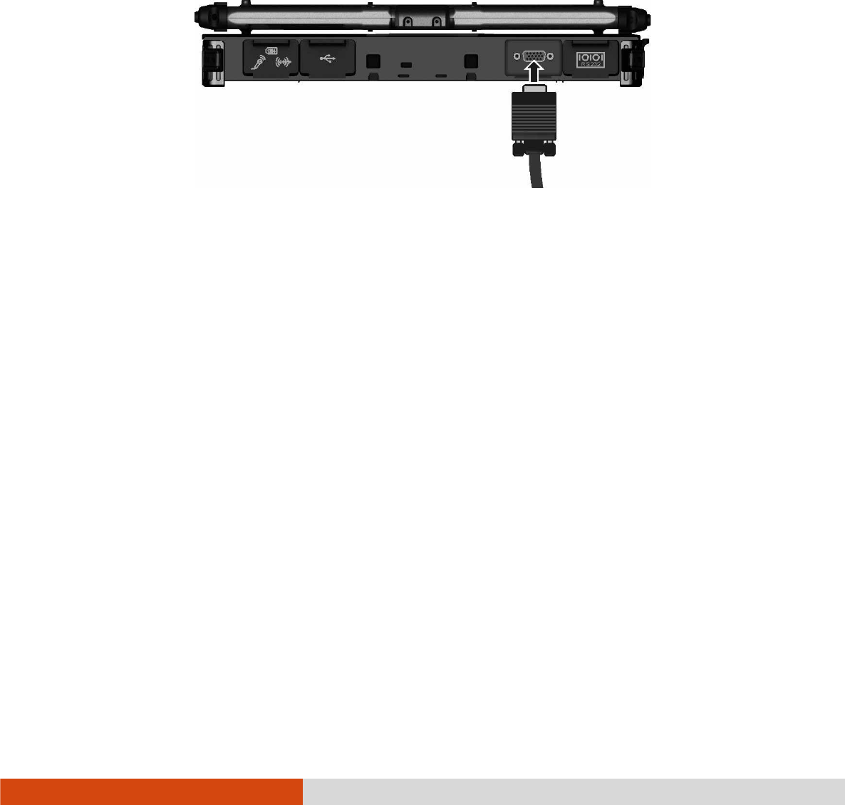
4-2 Expanding Your Computer
Connecting an External Monitor
Connecting an External MonitorConnecting an External Monitor
Connecting an External Monitor
If you want the benefits of a larger display screen with higher resolution, you can
connect an external display monitor to your computer. Follow this procedure to connect
an external monitor:
1. Make sure that the computer is not turned on.
2. Plug the monitor’s D-type signal connector to the computer’s VGA connector.
3. Plug one end of the monitor’s power cord into the power socket on the monitor
and the other end to an electrical outlet.
4. To use the monitor, turn on the monitor before turning on the computer.
5. The monitor should respond by default. If not, you can switch the display to
the monitor or to both (simultaneous display), or to multi-display by pressing
the Fn
FnFn
Fn+F5
F5F5
F5 hot key. In Windows, you can also change the display through the
settings in Display
DisplayDisplay
Display Properties.
6. You can change display settings through your operating system. See your operating
system documentation or online help for specific information.
CAUTION: Do not disconnect the external monitor while the computer is in the
Sleep mode or Hibernation mode. If no external monitor is connected when the
computer resumes, the LCD might not display properly.
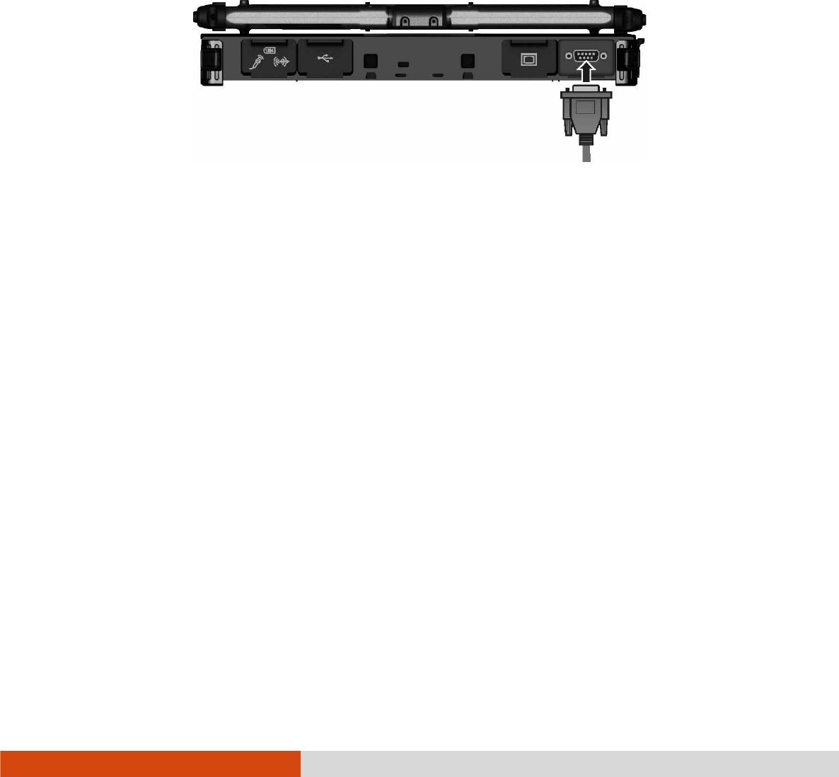
Expanding Your Computer 4-3
Connecting a Serial Device
Connecting a Serial DeviceConnecting a Serial Device
Connecting a Serial Device
Your computer has one or two serial port (depending on model) for connecting
a serial device such as a serial mouse or serial communication device (modem).
Follow this procedure to connect a serial device:
1. Make sure the computer is not turned on
2. Plug the device cable to the serial port on the rear of the computer.
3. Turn on the computer.
NOTE: Portable modems that derive power through the serial port cannot be used
with the computer. Instead, use a modem that is powered by its own internal
battery or external AC power.
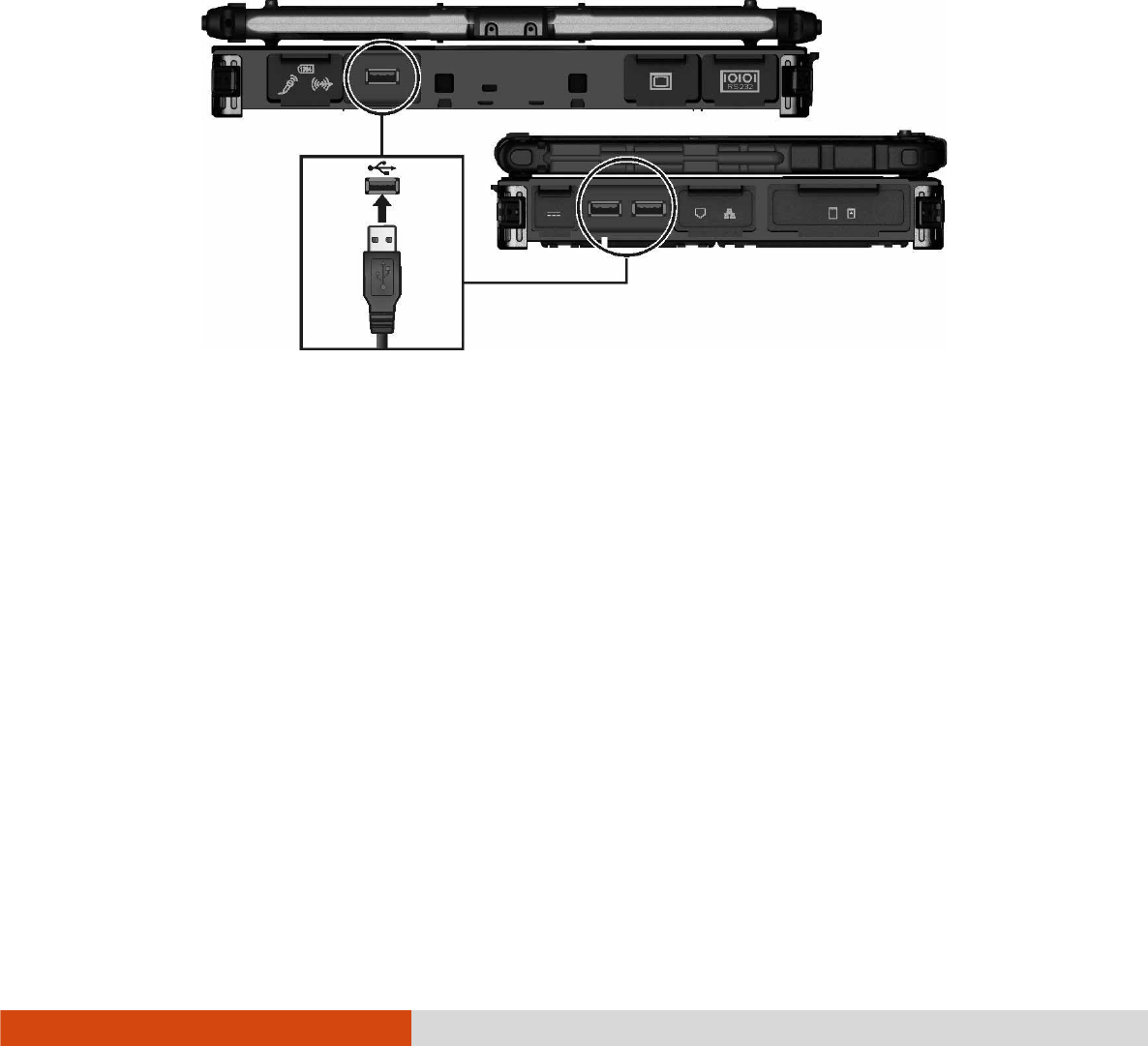
4-4 Expanding Your Computer
Connecting a USB Device
Connecting a USB DeviceConnecting a USB Device
Connecting a USB Device
Your computer has three USB ports (two USB 3.0 ports at the left side and one
USB 2.0 port at the back) for connecting USB devices, such as a digital camera,
scanner, printer, modem, and mouse.
USB 3.0 supports a transfer rate up to 5 Gbit/s and USB 2.0 a transfer rate up
to 12 MB/s.
To connect a USB device, plug the device cable to a matching USB port.
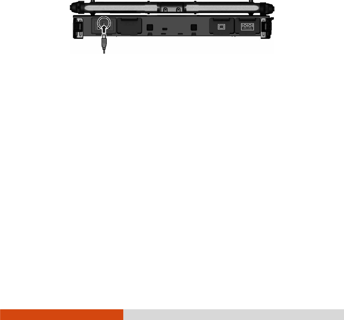
Expanding Your Computer 4-5
Connecting an IEEE 1394 Device
Connecting an IEEE 1394 DeviceConnecting an IEEE 1394 Device
Connecting an IEEE 1394 Device
Your computer has a mini IEEE 1394a port for connecting IEEE 1394 devices that
include not only computer peripheral devices such as scanner, printer and high-quality
CCD, but also consumer electronic equipment such as DVCAM and VCR.
To connect an IEEE 1394 device, prepare an IEEE 1394 cable. Plug the appropriate
end of the cable to the computer’s mini IEEE 1394 connector and the other end
to the device’s corresponding connector.
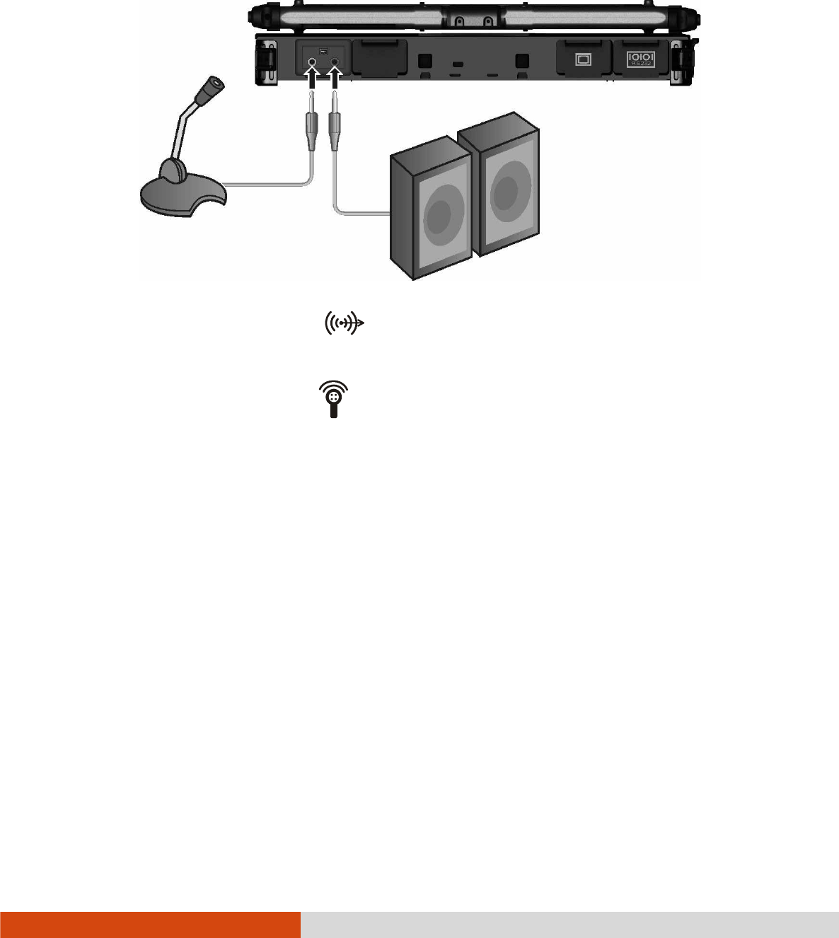
4-6 Expanding Your Computer
Connecting Audio Devices
Connecting Audio DevicesConnecting Audio Devices
Connecting Audio Devices
For higher audio quality, you can send or receive sound through external audio devices.
Audio Output Connector
Audio Output Connector Audio Output Connector
Audio Output Connector ( )
can be connected to speakers, headphones,
or earphone set.
Microphone Connector
Microphone Connector Microphone Connector
Microphone Connector ( )
can be connected to an external microphone
for recording voice or sound.
NOTE:
After connecting an external audio device, make sure that you specify the use
of the correct audio device in Windows.
When using the external speakers/headphones or microphone, you cannot
use the internal one.
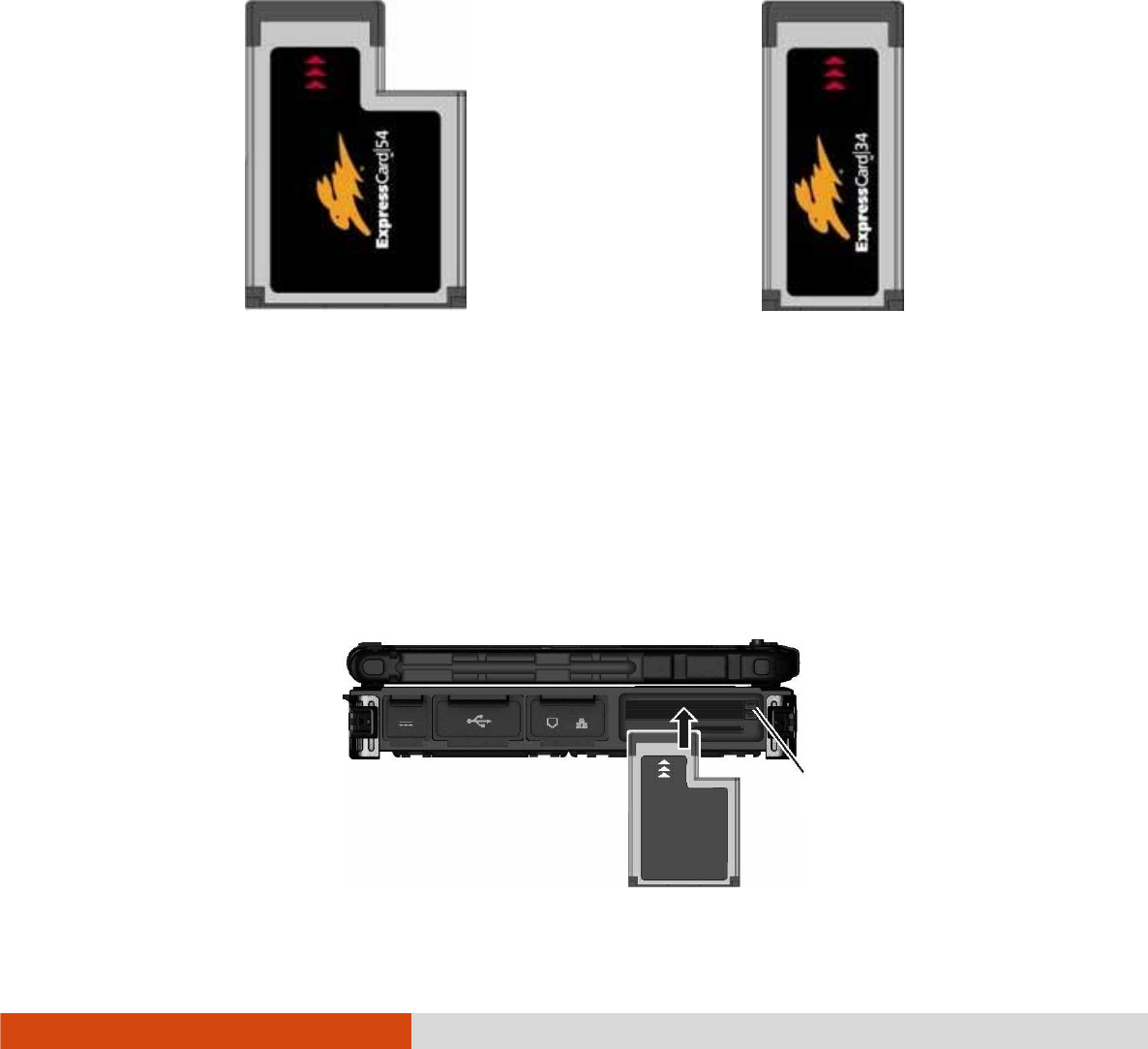
Expanding Your Computer 4-7
Using ExpressCards
Using ExpressCardsUsing ExpressCards
Using ExpressCards
Your computer has an ExpressCard slot.
The ExpressCard slot can accommodate a 54 mm (ExpressCard/54) or 34 mm
(ExpressCard/34) wide ExpressCard. Typical ExpressCards support a very extensive
range of applications including memory, wired and wireless communication cards, and
security devices.
Shown next are the appearances of ExpressCards for your reference.
ExpressCard/54 ExpressCard/34
To insert an ExpressCard:
1. Locate the ExpressCard slot on the left side of the computer. It can be the
upper slot (standard configuration) or lower slot depending on your model.
2. Slide the ExpressCard, with its label facing up, all the way into the slot until
the rear connectors click into place.
Eject button

4-8 Expanding Your Computer
3. When a new card is seated, the computer will detect it and try to install the
appropriate driver. Follow the on-screen instructions to complete the process.
To remove an ExpressCard:
1. Double-click on the Safely Remove Hardware
Safely Remove Hardware Safely Remove Hardware
Safely Remove Hardware icon ( ) found on the
Windows taskbar and the Safely Remove Hardware
Safely Remove HardwareSafely Remove Hardware
Safely Remove Hardware window appears on screen.
2. Select (highlight) the ExpressCard from the list to disable the card.
3. Push the eject button and the card will slide out slightly.
4. Pull the card out of the slot.
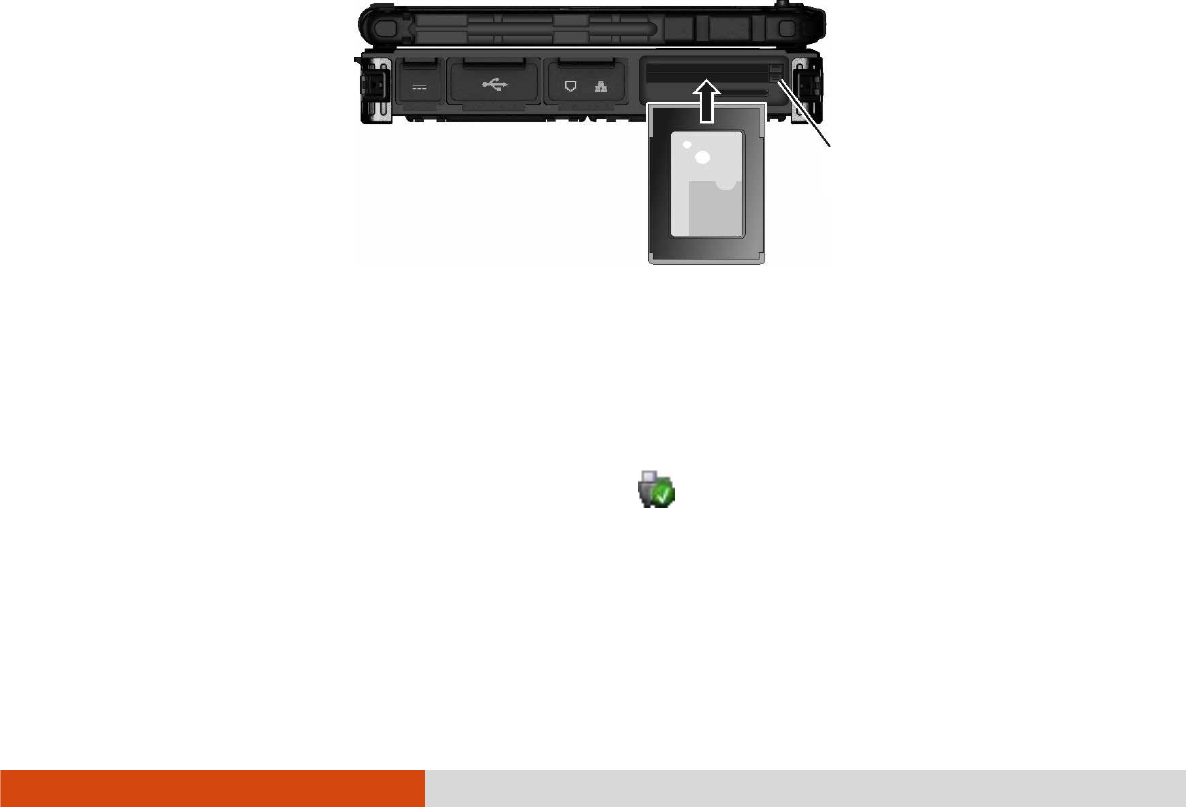
Expanding Your Computer 4-9
Using PC Cards
Using PC CardsUsing PC Cards
Using PC Cards
NOTE:
Some PC cards require additional system resources. Before using such PC
card, you may have to free other system resources for the PC card.
Although some PC cards can be inserted and removed without turning off the
computer, you cannot remove or install PC cards during Sleep mode.
Your computer (standard configuration) has one PC card slot that support CardBus
specifications. The slots can accommodate a type II card. Typical type II cards are
flash memory, SRAM, modem, LAN, and SCSI cards.
To insert a PC card:
1. Locate the PC card slot (the lower slot) on the left side of the computer.
2. Slide the PC card, with its label facing up, into the slot until the eject button
pops out.
3. When a new card is seated, the computer will detect it and try to install the
appropriate driver. Follow the on-screen instructions to complete the process.
To remove a PC card:
1. Double-click the Safely Remove Hardware
Safely Remove Hardware Safely Remove Hardware
Safely Remove Hardware icon found on the Windows taskbar
and the Safely Remove Hardware
Safely Remove HardwareSafely Remove Hardware
Safely Remove Hardware window appears on screen.
2. Select (highlight) the PC card from the list to disable the card.
Eject button

4-10 Expanding Your Computer
3. Push the eject button and the card will slide out slightly.
4. Pull the card out of the slot.
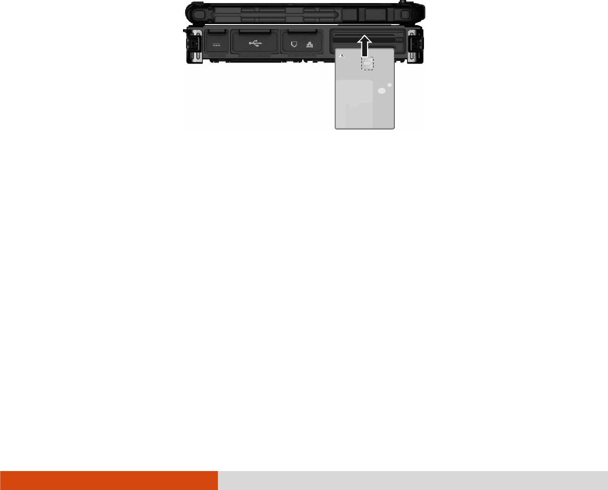
Expanding Your Computer 4-11
Using Smart Cards (Optional)
Using Smart Cards (Optional)Using Smart Cards (Optional)
Using Smart Cards (Optional)
Your computer may have a smart card reader.
With an embedded microcontroller, smart cards have the unique ability to store large
amounts of data, carry out their own on-card functions (e.g., encryption and mutual
authentication), and interact intelligently with a smart card reader.
To insert a smart card:
1. Locate the smart card slot.
2. Slide the smart card, with its label and embedded computer chip facing up into
the slot.
3. When a new card is seated, use the third-party smart card software to allow
your computer to read it.
To remove a smart card:
1. Make sure that the third-party smart card software is not accessing the smart
card.
2. Pull the card out of the slot.
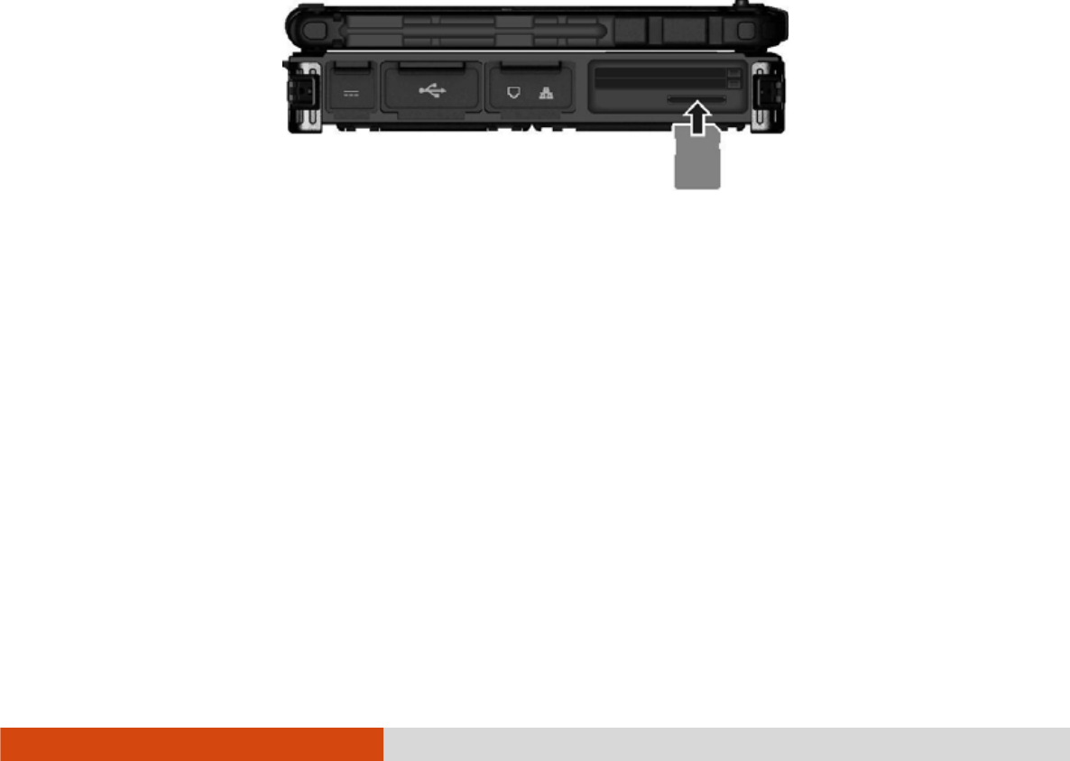
4-12 Expanding Your Computer
Using Storage Cards
Using Storage CardsUsing Storage Cards
Using Storage Cards
NOTE: You can use only storage cards. Your SD card reader does not support
cards with I/O (input/output) functions such as a wireless network card or
Bluetooth card.
Your computer has an SD card reader. The card reader is a small drive for reading
from and writing to removable storage cards (or called memory cards). The card
reader supports SD (Secure Digital), SDHC (Secure Digital High Capacity), and
SDXC (Secure Digital eXtended Capacity) cards.
To insert a storage card:
1. Locate the SD card reader on the left side of the computer.
2. Align the card with its connector pointing to the slot and its label facing up.
Slide the card into the slot until it reaches the end.
3. Windows will detect the card and assign it a drive name.
To remove a storage card:
1. Double-click My Computer
My ComputerMy Computer
My Computer.
2. Right-click the drive with the card and select Eject
EjectEject
Eject.
3. Push the card to release and then pull the card out of the slot.

Expanding Your Computer 4-13
System Memory Upgrade
System Memory UpgradeSystem Memory Upgrade
System Memory Upgrade
You can upgrade your computer by expanding system memory.
CAUTION:
It is not recommended that you buy and install RAM modules by yourself. If
you want to expand system memory, please ask Getac service center to install
DRAM modules for you so that full compatibility can be guaranteed.
RAM modules are extremely sensitive to static electricity. There are cases
where static electricity generated by the human body has adversely affected
such modules. When inserting or removing a RAM module, do not touch the
terminals or internal components, insert objects other than the module, or
allow foreign particles to enter. Doing so has been known to cause damage,
fire, or electrical shock.
To install the RAM module:
1. Remove the battery pack (see chapter 3) and make sure that the computer
is not connected to AC power.
2. Carefully place the computer upside down.
3. Remove the four screws to open the compartment cover.
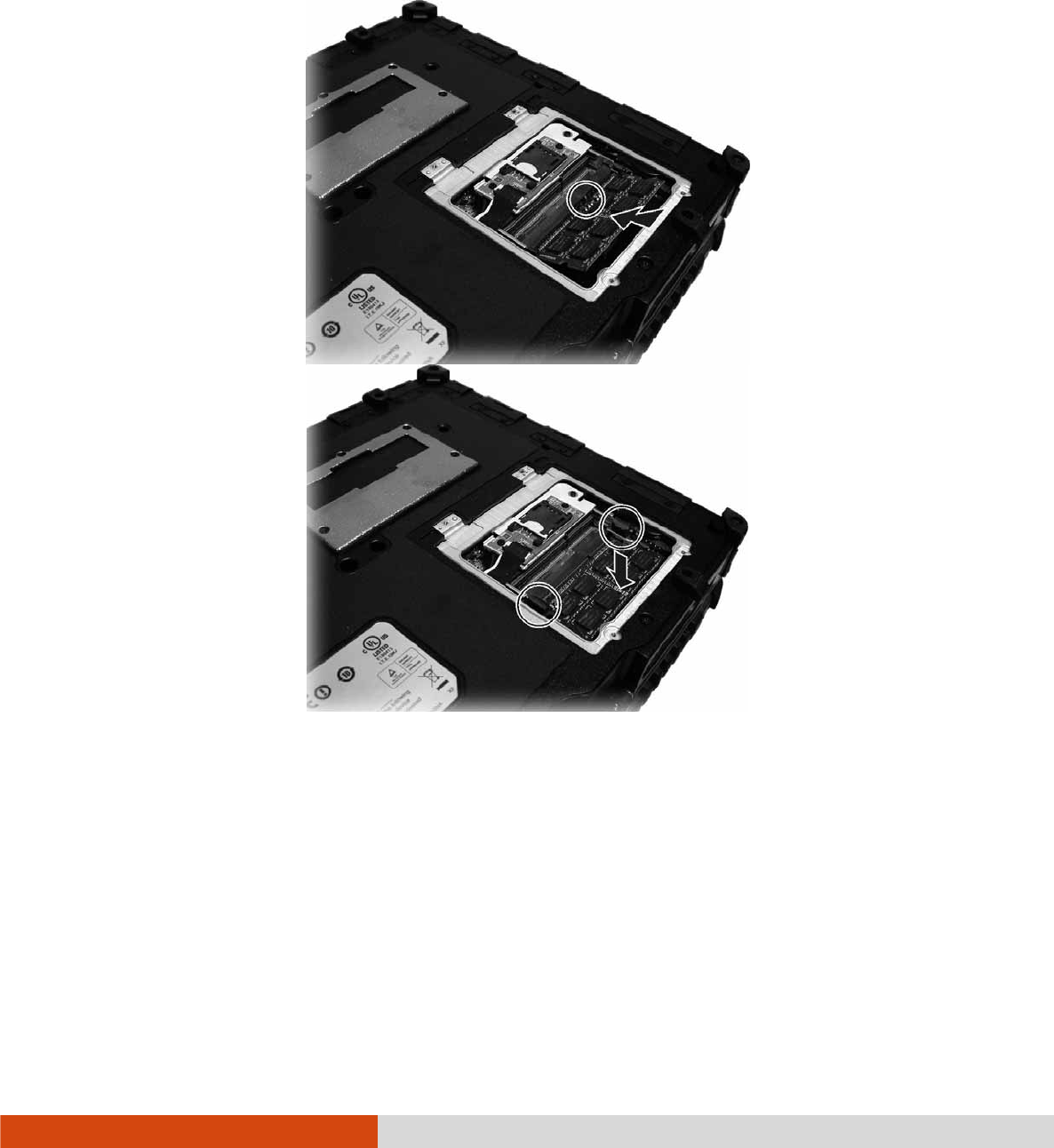
4-14 Expanding Your Computer
4. To install the RAM module, match the module's notched part with the socket's
projected part and firmly insert the module into the socket at a 20-degree angle.
Then push down until the retaining clips lock the module into position.
CAUTION: If the RAM module is difficult to insert or difficult to push down, do not
force it. Check once more to ensure that the module is positioned correctly.
5. Close the compartment cover and secure with four screws.

Using BIOS Setup and System Recovery 5-1
Chapter 5
Chapter 5Chapter 5
Chapter 5
Using BIOS Setup and
Using BIOS Setup and Using BIOS Setup and
Using BIOS Setup and
System Recovery
System RecoverySystem Recovery
System Recovery
BIOS Setup Utility is a program for configuring the BIOS (Basic Input/ Output
System) settings of the computer. BIOS is a layer of software, called firmware, that
translates instructions from other layers of software into instructions that the computer
hardware can understand. The BIOS settings are needed by your computer to identify
the types of installed devices and establish special features.
System Recovery reinstalls Windows to your computer and restores it to the factory
default status.
This chapter tells you how to use the BIOS Setup and System Recovery.

5-2 Using BIOS Setup and System Recovery
BIOS Setup
BIOS SetupBIOS Setup
BIOS Setup
When and How to Us
When and How to UsWhen and How to Us
When and How to Use
ee
e
You need to run BIOS Setup Utility when:
You see an error message on the screen requesting you to run BIOS Setup
Utility.
You want to restore the factory default BIOS settings.
You want to modify some specific settings according to the hardware.
You want to modify some specific settings to optimize the system performance.
To run BIOS Setup Utility, press the F2
F2F2
F2 key when the prompt appears on the screen
during the system startup. The prompt shows up on the screen for only a few seconds.
You must press the F2
F2F2
F2 key quickly. The BIOS Setup Utility main screen appears
as shown next.
Information Main Advanced Security Boot Exit
Model NO:
Serial NO:
Asset Tag:
Processor Info:
Installed System Memory:
SATA HDD:
BIOS Revision:
EC Revision:
LAN MAC Address:
IEEE 1394 GUID:
Operating Time:
V
200-G2
RC6XXV0026
Intel(R) Core(TM) i5-3320M CPU @2.60GHz
4096 MB
TOSHIBA MQ01ABD032 – 320.0 GB
R1.50.070520G
R0.50P.070520
00-22-20-0D-98-C0
00-40-D0-01-00-49-00-D6
184 Hours
F1 Help ĖĘ
ĖĘĖĘ
ĖĘ Select Item +/- Change Values F9 Setup Defaults
Esc Exit ĕė
ĕėĕė
ĕė Select Menu Enter Select
Sub-Menu F10 Save and Exit

Using BIOS Setup and System Recovery 5-3
In general, you can use the arrow keys to move around and + / – keys to change
the setup values. Keyboard information can be found at the bottom of the screen.
NOTE:
The BIOS Setup Utility screens shown in this chapter are for your reference
only. The actual items or settings on your computer may differ.
The BIOS Setup Utility program may have been updated after the publication
of this manual.
The settings you select in your operating system might override similar
settings in BIOS Setup Utility.
Information Menu
Information MenuInformation Menu
Information Menu
The Information menu contains the basic configuration information of the system. There
are no user-definable items in this menu.
Information Main Advanced Security Boot Exit
Model NO:
Serial NO:
Asset Tag:
Processor Info:
Installed System Memory:
SATA HDD:
BIOS Revision:
EC Revision:
LAN MAC Address:
IEEE 1394 GUID:
Operating Time:
V
100-G4
RC5XXV0043
Intel(R) Core(TM) i5-3320M CPU @2.60GHz
8192 MB
LITEONIT LAT-128M3S – 128 GB
R1.01.070520U
R0.50M.070520
00-22-20-0D-A8-A7
00-40-D0-01-00-49-00-2D
80 Hours
F1 Help ɥɧ
ɥɧɥɧ
ɥɧ Select Item +/- Change Values F9 Setup Defaults
Esc Exit ɤɦ
ɤɦɤɦ
ɤɦ Select Menu Enter Select
Sub-Menu F10 Save and Exit
NOTE: The “Asset Tag” information appears when you have entered the asset
number for this computer using the asset management program. The program is
provided in the Asset tag folder of the Driver disc.

5-4 Using BIOS Setup and System Recovery
Main Menu
Main MenuMain Menu
Main Menu
The Main menu contains various system settings.
Information Main Advanced Security Boot Exit
System Date:
System Time:
Legacy USB Support:
[05/28/2012]
[11:33:08]
[Enabled]
Item Specific Help
View or set system
date.
F1 Help ĖĘ
ĖĘĖĘ
ĖĘ Select Item +/- Change Values F9 Setup Defaults
Esc Exit ĕė
ĕėĕė
ĕė Select Menu Enter Select
Sub-Menu F10 Save and Exit
System Time
System TimeSystem Time
System Time sets the system time.
System Date
System DateSystem Date
System Date sets the system date.
Legacy USB Support
Legacy USB SupportLegacy USB Support
Legacy USB Support enables or disables the system’s support for Legacy USB device
in DOS mode.
05
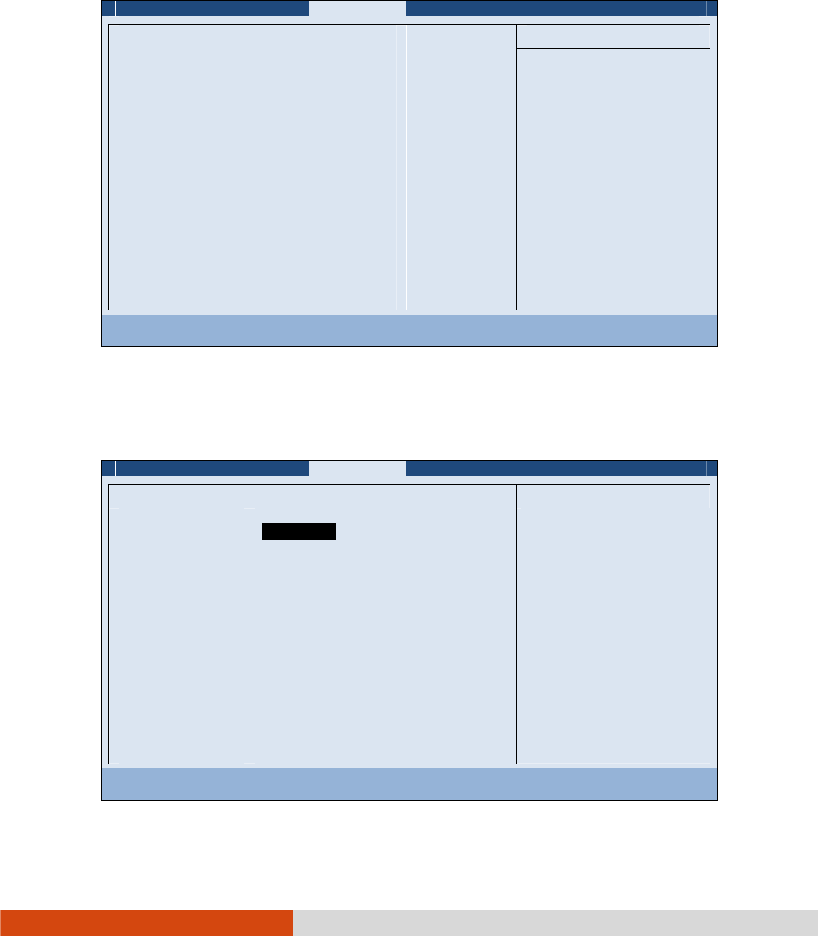
Using BIOS Setup and System Recovery 5-5
Advanced Menu
Advanced MenuAdvanced Menu
Advanced Menu
The Advanced menu contains the advanced settings as shown next.
Information Main Advanced Security Boot Exit
Intel (R) Rapid Start Technology
Wake Up Capability
System Policy
AC Initiation:
SATA Mode:
AMT Configuration
Virtualization Technology Setup
Graphic Setup
Device Configuration
Serial COM Port Configuration
[Performance]
[Disabled]
[AHCI]
Item Specific Help
iRST – Intel (R) Rapid
Start Technology
Configuration
F1 Help ĖĘ
ĖĘĖĘ
ĖĘ Select Item +/- Change Values F9 Setup Defaults
Esc Exit ĕė
ĕėĕė
ĕė Select Menu Enter Select
Sub-Menu F10 Save and Exit
Intel (R) Rapid Start Technology
Intel (R) Rapid Start Technology Intel (R) Rapid Start Technology
Intel (R) Rapid Start Technology configures iRST. Press Enter
Enter Enter
Enter to access the submenu
as shown below.
Advanced
Intel (R) Rapid Start Technology Item Specific Help
iRST Support: [Disabled ] Enable iRST.
F1 Help ĖĘ
ĖĘĖĘ
ĖĘ Select Item +/- Change Values F9 Setup Defaults
Esc Exit ĕė
ĕėĕė
ĕė Select Menu Enter Select
Sub-Menu F10 Save and Exit
Disabled

5-6 Using BIOS Setup and System Recovery
iRST Support enables of disables iRST, which gets your system up and running
faster.
Wake Up Capability
Wake Up CapabilityWake Up Capability
Wake Up Capability specifies events for waking up the system. Press Enter
Enter Enter
Enter to access
the submenu as shown below.
Advanced
Wake Up Capability Item Specific Help
Ring Wake Up From S3:
USB Wake Up From S3:
Wake on PCH LAN:
[Disabled]
[Disabled]
[Disabled]
Allow a modem
activity to wake up
the system from
S3(Sleep) state.
F1 Help ĖĘ
ĖĘĖĘ
ĖĘ Select Item +/- Change Values F9 Setup Defaults
Esc Exit ĕė
ĕėĕė
ĕė Select Menu Enter Select
Sub-Menu F10 Save and Exit
Ring Wake Up From S3 allows a modem device activity to wake up the system
from S3 (Sleep) state.
USB Wake Up From S3 allows a USB device activity to wake up the system from
S3 (Sleep) state.
Wake on PCH LAN allows a LAN activity to wake up the system from S3 (Sleep)
state.
System Policy
System Policy System Policy
System Policy sets if the system always runs at full speed (
Performance
) or lowers
down when its temperature is too high (
Balance
).
AC Initiation
AC Initiation AC Initiation
AC Initiation sets if connecting AC power will automatically start or resume your
computer.
SATA Mode
SATA ModeSATA Mode
SATA Mode set to
AHCI
if your hard disk supports AHCI. AHCI allows you to take
advantage of Advanced Host Controller Interface features. The options are
IDE
and
AHCI
.
CAUTION: Incorrect SATA mode settings can result in hard disk drive boot failure.
Disabled

Using BIOS Setup and System Recovery 5-7
AMT Configuration
AMT ConfigurationAMT Configuration
AMT Configuration configures Active Management Technology parameters. Press
Enter
Enter Enter
Enter to access the submenu as shown below.
Advanced
AMT Configuration Item Specific Help
Intel AMT:
Intel AMT Setup Prompt:
[Disable ]
[Disabled]
Enable/Disable
Intel (R) Active
Management Technology
BIOS Extension.
Note: iAMT H/W is
always enabled.
This option just
controls the BIOS
extension execution.
If enabled this
requires additional
firmware in the SPI
device
F1 Help ĖĘ
ĖĘĖĘ
ĖĘ Select Item +/- Change Values F9 Setup Defaults
Esc Exit ĕė
ĕėĕė
ĕė Select Menu Enter Select
Sub-Menu F10 Save and Exit
Intel AMT enables or disables Intel® Active Management Technology BIOS
extension execution. AMT allows the system administrator to access an AMT
featured computer remotely.
Intel AMT Setup Prompt
Intel AMT Setup PromptIntel AMT Setup Prompt
Intel AMT Setup Prompt determines whether the prompt for entering Intel AMT
Setup appears or not during POST. If disabled, users cannot enter Intel AMT
Setup.
Virtualization Technology Setup
Virtualization Technology SetupVirtualization Technology Setup
Virtualization Technology Setup sets Virtualization Technology parameters. Press Enter
Enter Enter
Enter
to access the submenu as shown below.
Enabled

5-8 Using BIOS Setup and System Recovery
Advanced
Virtualization Technology Setup Item Specific Help
Intel(R) Virtualization Technology
Intel(R) VT for Directed I/O (VT-d)
[Disabled]
[Disabled]
When enabled, a VMM
can utilize the
additional hardware
capabilities.
F1 Help ĖĘ
ĖĘĖĘ
ĖĘ Select Item +/- Change Values F9 Setup Defaults
Esc Exit ĕė
ĕėĕė
ĕė Select Menu Enter Select
Sub-Menu F10 Save and Exit
Intel(R) Virtualization Technology
Intel(R) Virtualization TechnologyIntel(R) Virtualization Technology
Intel(R) Virtualization Technology enables or disables Intel® VT (Intel
Virtualization Technology) feature which provides hardware support for processor
virtualization. When enabled, a VMM (Virtual Machine Monitor) can utilize the
additional hardware virtualization capabilities provided by this technology.
Intel(R) VT for Directed I/O (VT
Intel(R) VT for Directed I/O (VTIntel(R) VT for Directed I/O (VT
Intel(R) VT for Directed I/O (VT-
--
-d)
d)d)
d) enables or disables VT-d (Intel® Virtualization
Technology for Directed I/O). When enabled, VT-d helps enhance Intel platforms
for efficient virtualization of I/O devices.
Graphics Setup
Graphics SetupGraphics Setup
Graphics Setup sets graphics related options. Press Enter
Enter Enter
Enter to access the submenu
as shown below.
Disabled

Using BIOS Setup and System Recovery 5-9
Advanced
Graphic Setup Item Specific Help
DVMT Pre-Allocated:
Total Graphics Memory:
[ ]
[256MB]
Select Pre-Allocated
Graphics Memory size
used by the Internal
Graphics Device.
This has no effect if
external graphics are
present.
F1 Help ĖĘ
ĖĘĖĘ
ĖĘ Select Item +/- Change Values F9 Setup Defaults
Esc Exit ĕė
ĕėĕė
ĕė Select Menu Enter Select
Sub-Menu F10 Save and Exit
NOTE: Graphic Setup parameters apply to the internal graphics device only.
DVMT Pre
DVMT PreDVMT Pre
DVMT Pre-
--
-Allocated
Allocated Allocated
Allocated sets the amount of pre-allocated (fixed) graphics memory
for use by the internal graphics device.
Total Graphics Memory
Total Graphics Memory Total Graphics Memory
Total Graphics Memory sets the amount of total graphics memory (pre-allocated
+ fixed + DVMT) for use by the internal graphics device.
64MB

5-10 Using BIOS Setup and System Recovery
Device Configuration enables or disables several hardware components. Press Enter
to access the submenu as shown below.
Advanced
Device Configuration Item Specific Help
Wireless LAN:
WWAN:
Bluetooth:
Media Card Reader:
Smart Card Reader:
HD Audio:
Modem:
Fingerprint Scanner:
1394 Port:
Touch Screen:
GPS:
[ ]
[Enabled]
[Enabled]
[Enabled]
[Enabled]
[Enabled]
[Enabled]
[Enabled]
[Enabled]
[Enabled]
[Enabled]
Set WLAN device to
enable/disable.
F1 Help ĖĘ
ĖĘĖĘ
ĖĘ Select Item +/- Change Values F9 Setup Defaults
Esc Exit ĕė
ĕėĕė
ĕė Select Menu Enter Select
Sub-Menu F10 Save and Exit
You can enable or disable the following items:
Wireless LAN
WWAN
Bluetooth
Media Card Reader (SD)
Smart Card Reader
HD Audio (High Definition Audio)
Modem
Fingerprint Scanner
1394 Port
Touch Screen
GPS
Enabled

Using BIOS Setup and System Recovery 5-11
Serial COM Port Configuration enables or disables the serial port. Press Enter to
access the submenu as shown below.
Advanced
COM PORT Configuration Item Specific Help
Serial COM PORT1
Serial COM PORT2
Serial COM PORT3
[ ]
[Enabled]
[Enabled]
This option controls
the Onboard COM1
Address. When
enabled, COM1 uses
address 0x3F8h and
IRQ4.
F1 Help ĖĘ
ĖĘĖĘ
ĖĘ Select Item +/- Change Values F9 Setup Defaults
Esc Exit ĕė
ĕėĕė
ĕė Select Menu Enter Select
Sub-Menu F10 Save and Exit
Enabled
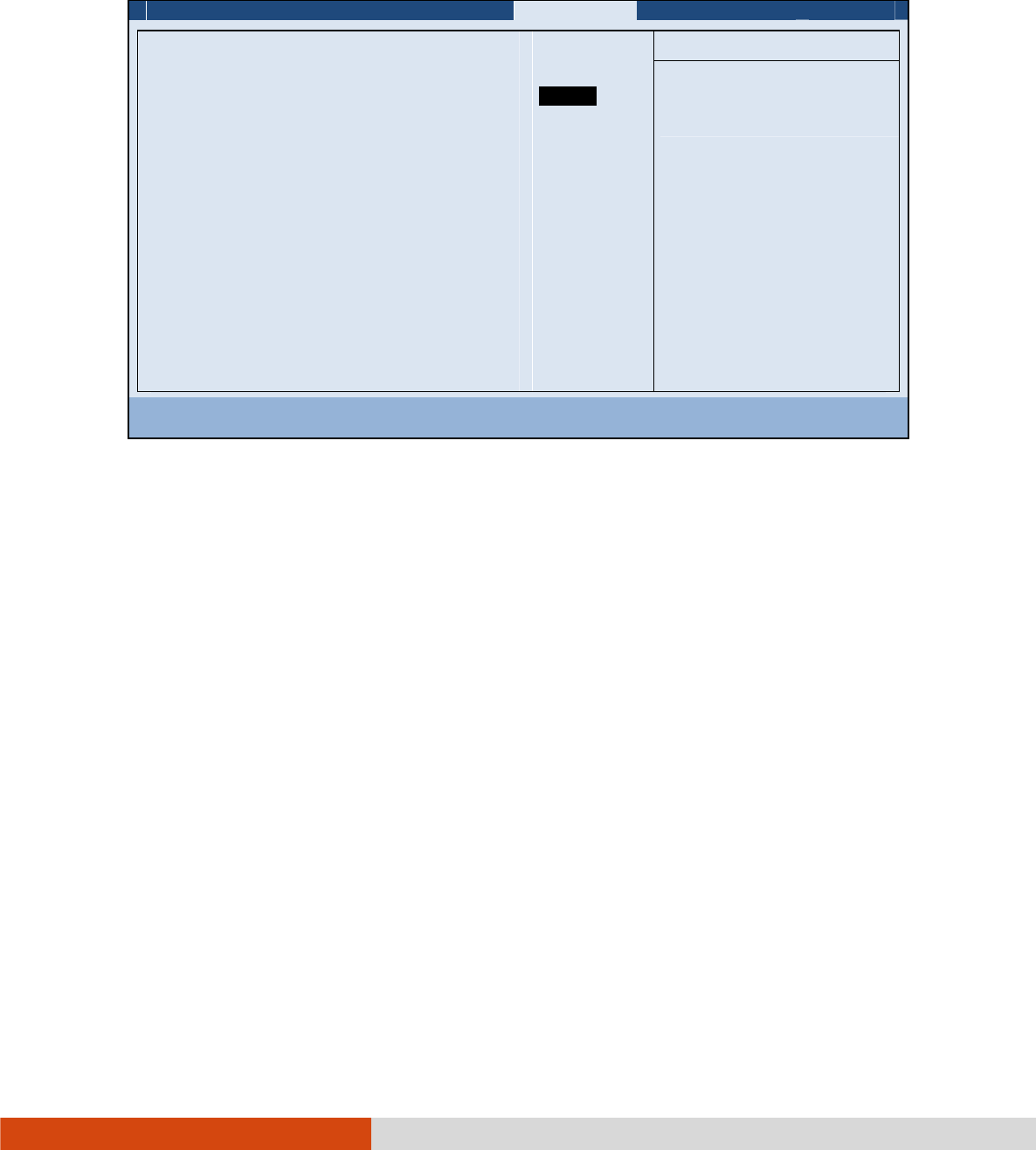
5-12 Using BIOS Setup and System Recovery
Security Menu
Security MenuSecurity Menu
Security Menu
The Security menu contains the security settings, which safeguard your system against
unauthorized use.
Information Main Advanced Security Boot Exit
Supervisor Password Is:
User Password Is:
Set Supervisor Password:
Set User Password
Password on Boot:
Set HDD 0 Password:
HDD 0 Password:
TPM Setup Menu
Intel Trusted Execution Technology
Cleared
Cleared
[Enter]
[Enter]
[Disabled]
[Enter]
Cleared
[Disabled]
Item Specific Help
Set or clear the
Supervisor account’s
password.
F1 Help ĖĘ
ĖĘĖĘ
ĖĘ Select Item +/- Change Values F9 Setup Defaults
Esc Exit ĕė
ĕėĕė
ĕė Select Menu Enter Select
Sub-Menu F10 Save and Exit
NOTE:
You can set the user password only when the supervisor password has been
set.
If both the administrator and user passwords are set, you can enter any of
them for starting up the system and/or entering BIOS Setup. However, the
user password only allows you to view/change the settings of certain items.
A password setting is applied right after it is confirmed. To cancel a password,
leave the password empty by pressing the Enter key.
Supervisor/User Password Is
Supervisor/User Password Is Supervisor/User Password Is
Supervisor/User Password Is shows whether you have set the supervisor/user
password or not for the system.
Set Supervisor/User Password
Set Supervisor/User PasswordSet Supervisor/User Password
Set Supervisor/User Password sets the supervisor/user password. When typing the
password, first make sure that Num Lock is off, and then type the password in
the entry fields and press Enter
EnterEnter
Enter. Confirm your password by typing it again and pressing
Enter

Using BIOS Setup and System Recovery 5-13
Enter
EnterEnter
Enter. You can set the supervisor/user password to be required for starting up the
system and/or entering BIOS Setup.
Password on Boot
Password on BootPassword on Boot
Password on Boot allows you to enable or disable the entering of password for booting
up your system. Once the password is successfully set and this item is enabled,
it is required for booting up the system.
Set HDD
Set HDD Set HDD
Set HDD 0 Password
0 Password0 Password
0 Password sets the password for locking the Primary Master hard disk
drive. After setting a password, the hard disk drive can only be unlocked by the
password no matter where it is installed.
HDD 0 Password Is
HDD 0 Password Is HDD 0 Password Is
HDD 0 Password Is shows whether you have set the hard disk password or not.
TPM Setup Menu
TPM Setup MenuTPM Setup Menu
TPM Setup Menu sets various TPM parameters. Press Enter
Enter Enter
Enter to access the submenu
as shown below.
T
TT
TPM Support
PM Support PM Support
PM Support enables or disables TPM (Trusted Platform Module) support. TPM
(Trusted Platform Module) is a component on your computer’s mainboard that
is specifically designed to enhance platform security by providing a protected space
for key operations and other security critical tasks.
Security
TPM Setup Menu Item Specific Help
TPM Support:
Current TPM State:
Change TPM Status:
[ ]
[Enabled and Activated]
[No Change]
This is used to
decide whether TPM
support should be
enabled or disabled.
F1 Help ĖĘ
ĖĘĖĘ
ĖĘ Select Item +/- Change Values F9 Setup Defaults
Esc Exit ĕė
ĕėĕė
ĕė Select Menu Enter Select
Sub-Menu F10 Save and Exit
Enabled

5-14 Using BIOS Setup and System Recovery
Current TPM State
Current TPM StateCurrent TPM State
Current TPM State shows the current TPM state.
Change TPM State
Change TPM State Change TPM State
Change TPM State allows you to select between
No Change
,
Clear
,
Deactivate
& Disable
, and
Enable & Activate
.
Intel Trusted Execution Technology enables utilization of additional hardware
capabilities provided by Intel® Trusted Execution Technology.
Boot Menu
Boot MenuBoot Menu
Boot Menu
The Boot menu sets the sequence of the devices to be searched for the operating
system.
Information Main Advanced Security Boot Exit
Boot priority order:
1. SATA ODD:
2. SATA HDD1: TOSHIBA MQ01ABD032
3. USB HDD:
4. USB FDD:
5. PCI LAN: IBA GE Slot 00C8 v1365
6. USB ODD:
7. Other HDD:
8. ESATA HDD:
Item Specific Help
Keys used to view or
configure devices:
and
arrows Select a
device. ’+’ and ’-’
moves the device up or
down. ’Shift + 1’
enables or disables a
device. ’Del’ deletes
an unprotected device.
F1 Help ĖĘ
ĖĘĖĘ
ĖĘ Select Item +/- Change Values F9 Setup Defaults
Esc Exit ĕė
ĕėĕė
ĕė Select Menu Enter Select
Sub-Menu F10 Save and Exit
The bootable devices will be automatically detected during POST and shown here,
allowing you to set the sequence that the BIOS uses to look for a device from which
to load the OS.
Below is a brief description of keyboard usage:
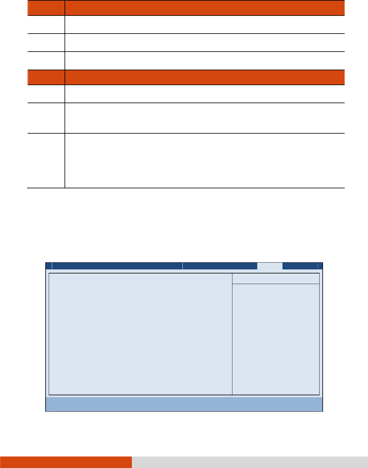
Using BIOS Setup and System Recovery 5-15
Key
KeyKey
Key
Function
FunctionFunction
Function
↑ , ↓ Selects (highlight) a boot device.
+, – Changes the boot sequence.
1
11
1 to 4
44
4 Loads the default boot sequence.
Key
KeyKey
Key
Function
FunctionFunction
Function
f
ff
f or r
rr
r
Specifies if the boot device is fixed (f
ff
f) or removable (r
rr
r).
X
XX
X Moves the highlighted boot device from the “Boot priority order” list to
the “Excluded from boot order” list, and vice versa.
Shift
ShiftShift
Shift+1
11
1Deactivates/activates the highlighted boot device on the “Boot priority
order” list. When a device has been deactivated, an “!” (exclamation)
symbol appears beside the item and system will bypass it when detecting
boot device during POST.
Exit Menu
Exit MenuExit Menu
Exit Menu
The Exit menu provides ways of exiting BIOS Setup. After finishing with your settings,
you must save and exit so that the changes can take effect.
Information Main Advanced Security Boot Exit
Exit Saving Changes
Exit Discarding Changes
Load Setup Defaults
Discard Changes
Save Changes
Item Specific Help
Equal to F10, save
all changes of all
menus, then exit
setup configure
driver. Finally
resets the system
automatically.
F1 Help ĖĘ
ĖĘĖĘ
ĖĘ Select Item +/- Change Values F9 Setup Defaults
Esc Exit ĕė
ĕėĕė
ĕė Select Menu Enter Select
Sub-Menu F10 Save and Exit

5-16 Using BIOS Setup and System Recovery
Exit Saving Changes
Exit Saving Changes Exit Saving Changes
Exit Saving Changes saves the changes you have made and exits BIOS Setup Utility.
Exit Discarding Changes
Exit Discarding Changes Exit Discarding Changes
Exit Discarding Changes exits BIOS Setup Utility without saving the changes you have
made.
Load Setup Defaults
Load Setup DefaultsLoad Setup Defaults
Load Setup Defaults loads the factory default values for all the items.
Discard Changes
Discard Changes Discard Changes
Discard Changes restores the previous values for all the items.
Saves Changes
Saves Changes Saves Changes
Saves Changes saves the changes you have made.