Getac Technology 301 NOTEBOOK PC User Manual B300 EN
Getac Technology Corp. NOTEBOOK PC B300 EN
UserManual.wiki
>
Getac Technology
>
301 User Manual
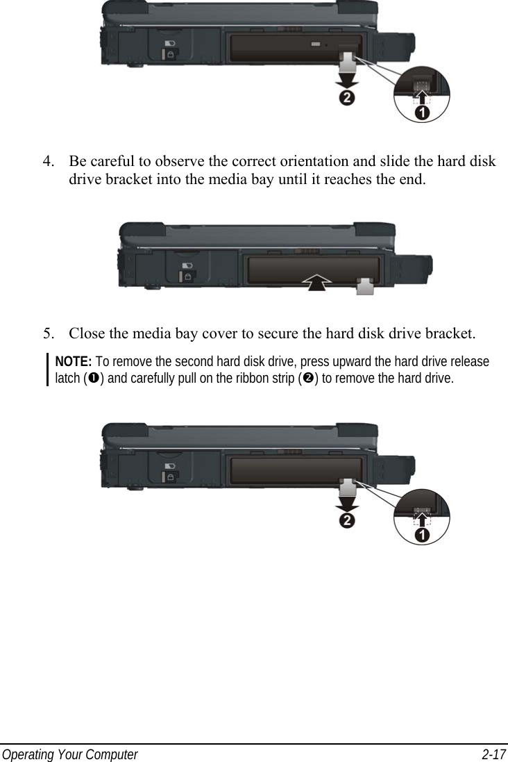
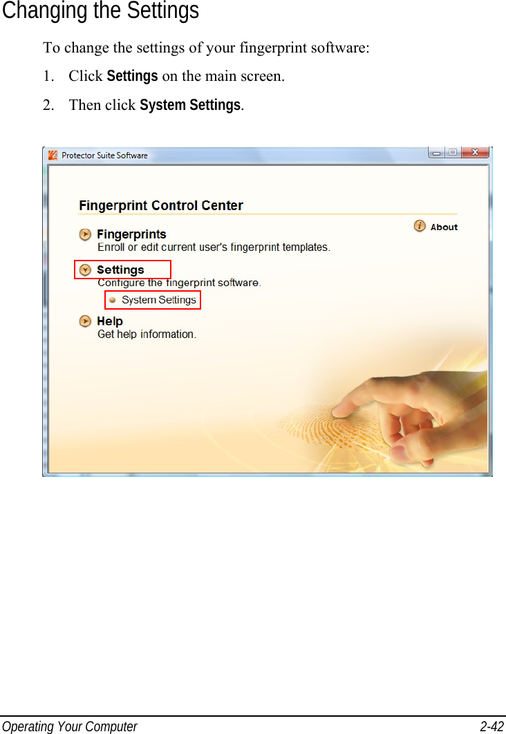
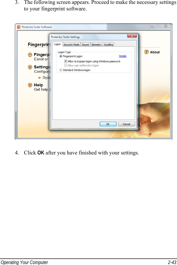
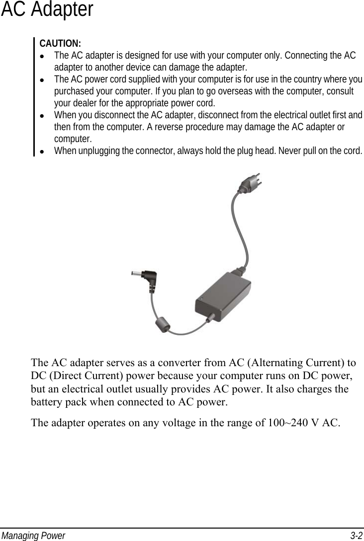
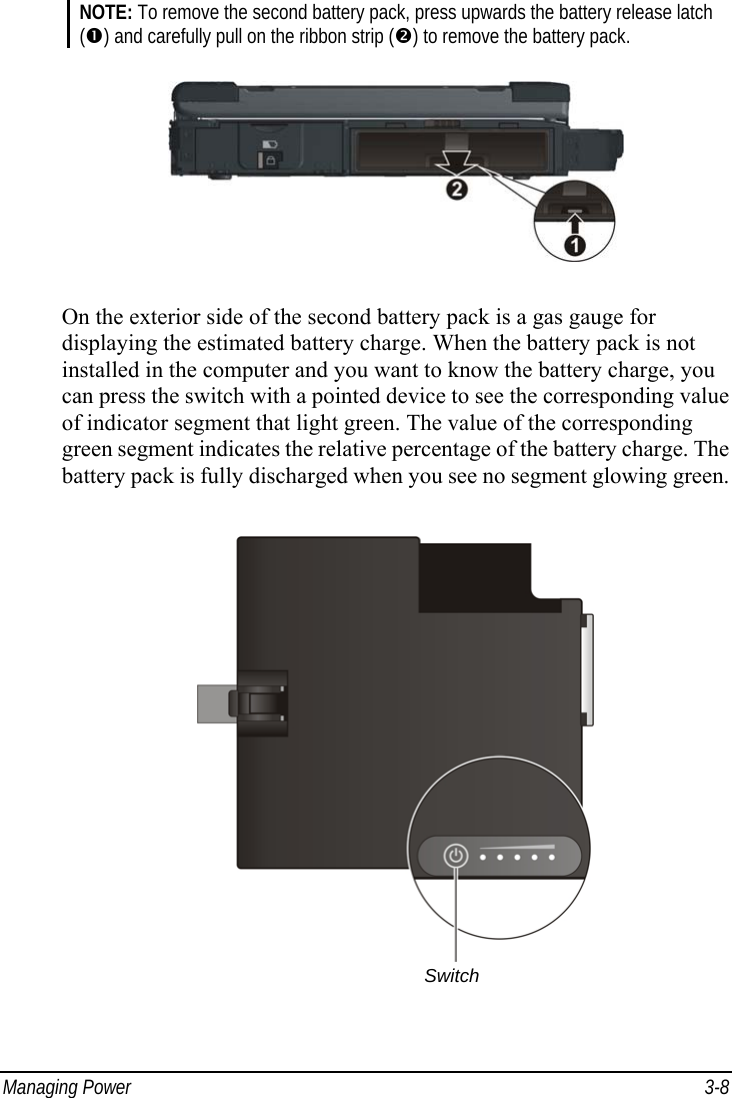
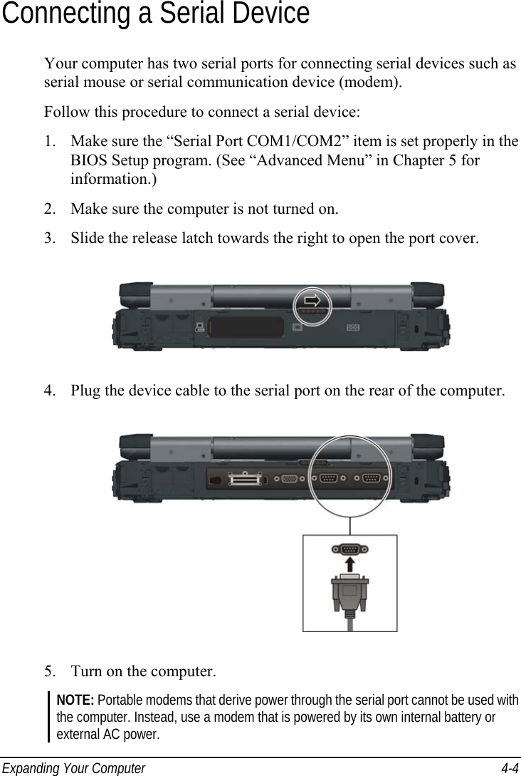
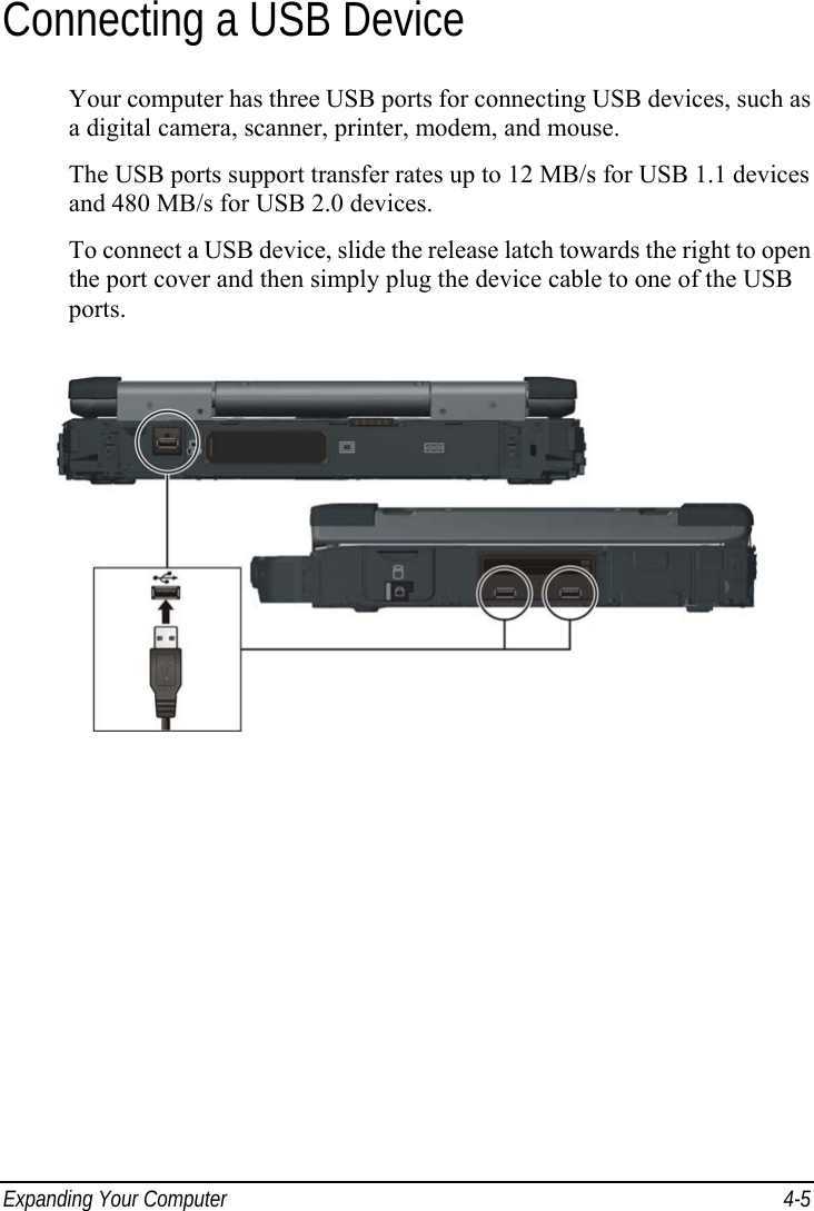
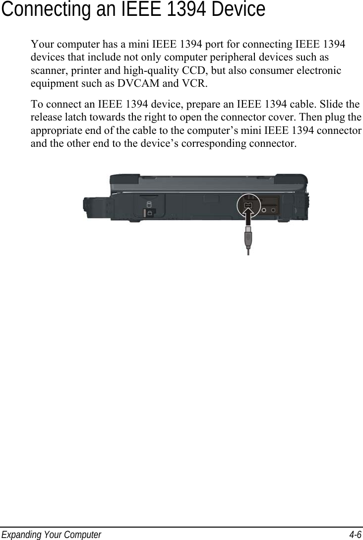
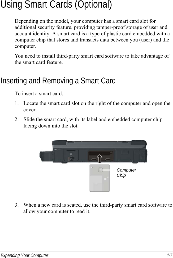
USERS MANUAL
Navigation menu
Upload a User Manual
Namespaces
Wiki Guide
HTML
PDF
Info
Views
User Manual
Discussion / Help
Navigation