Getac Technology 3X03 NOTEBOOK PC User Manual
Getac Technology Corporation NOTEBOOK PC Users Manual
UserManual.wiki
>
Getac Technology
>
3X03 User Manual
Users Manual
Navigation menu
Upload a User Manual
Namespaces
Wiki Guide
HTML
PDF
Info
Views
User Manual
Discussion / Help
Navigation


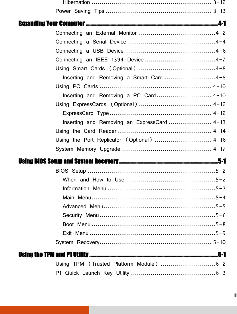


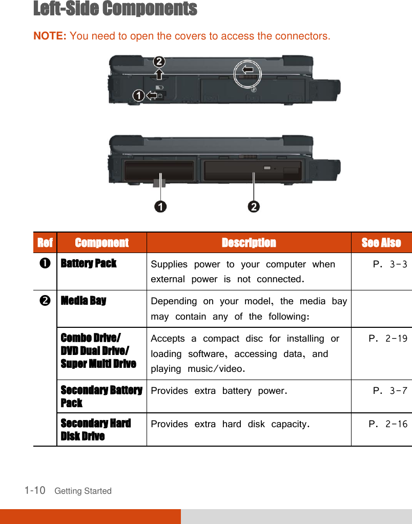
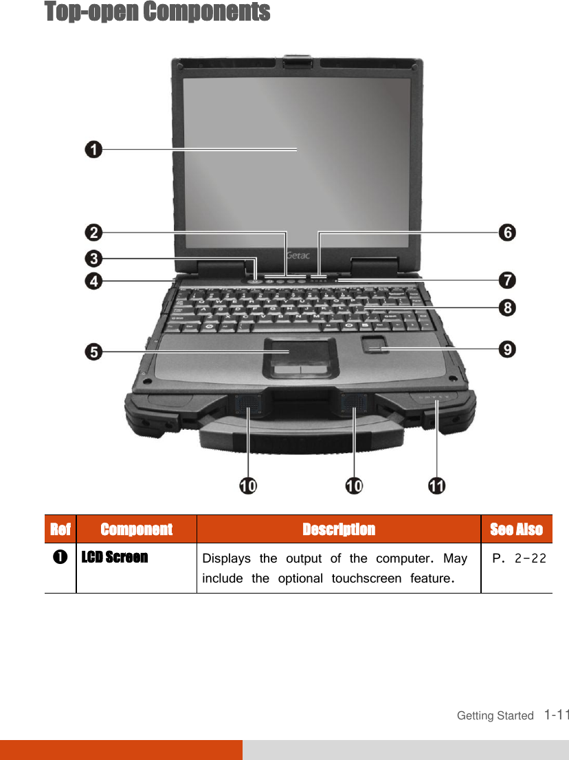


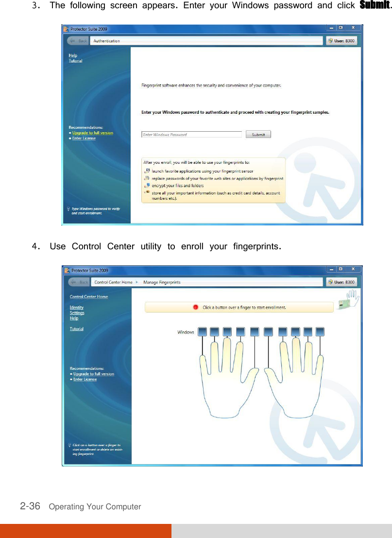


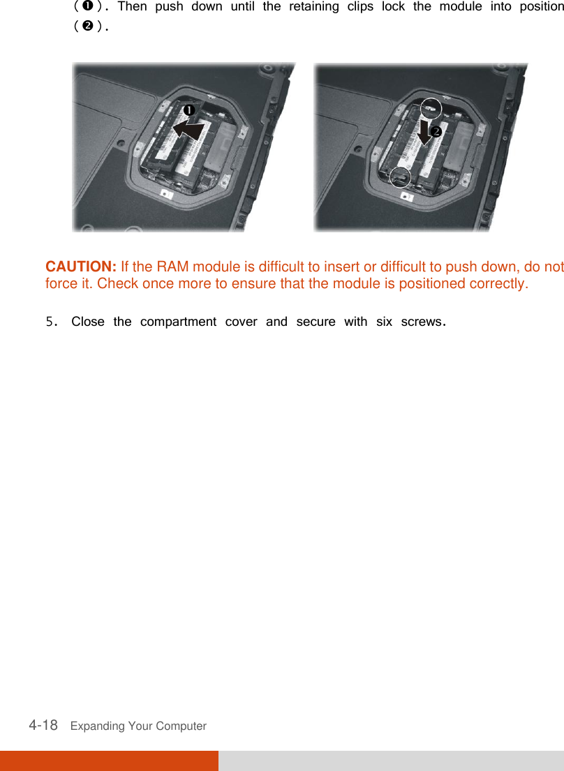
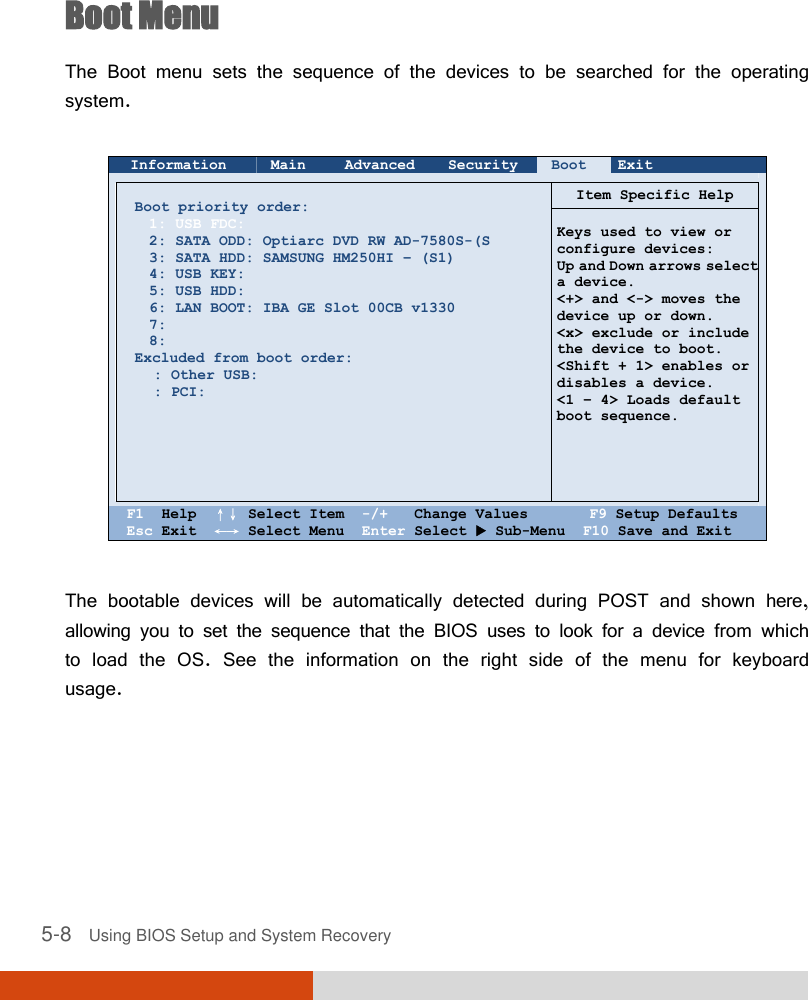
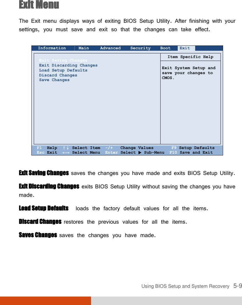
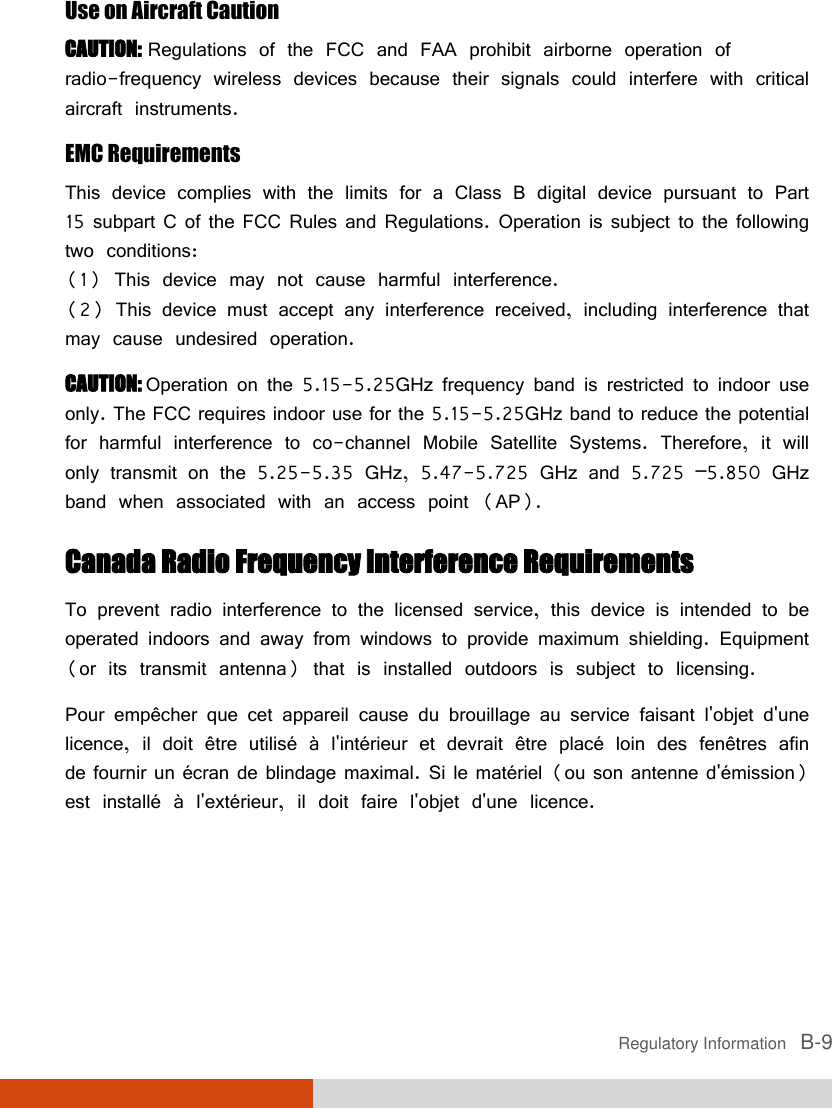
![5-2 Using BIOS Setup and System Recovery BIOS Setup When and How to Use You need to run BIOS Setup Utility when: You see an error message on the screen requesting you to run BIOS Setup Utility. You want to restore the factory default BIOS settings. You want to modify some specific settings according to the hardware . You want to modify some specific settings to optimize the system performance. To run BIOS Setup Utility, press the F2 key when the prompt appears on the screen during system startup. The prompt shows up on the screen for only a few seconds. You must press F2 quickly. The BIOS Setup Utility main screen appears as shown next. Information Main Advanced Security Boot Exit Serial NO: Processor Info: Installed System Memory: SATA HDD: SATA ODD: ESTAT Port: BIOS Revision: EC Revision: LAN MAC Address: IEEE 1394 GUID: Operating Time: 00000000000000 Intel(R) Core(TM) i7 CPU L620@2.00GHz 2048MB [SAMSUNG HM250HI] 250GB [Optiarc DVD RW AD-7580S] [None] R0.05.070520S R0.06F 00-22-20-0A-54-AE 00-40-D0-01-00-48-1A-F9 52 Hours F1 Help ↑↓ Select Item -/+ Change Values F9 Setup Defaults Esc Exit ←→ Select Menu Enter Select Sub-Menu F10 Save and Exit](https://usermanual.wiki/Getac-Technology/3X03/User-Guide-1432623-Page-98.png)
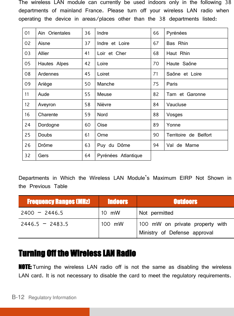
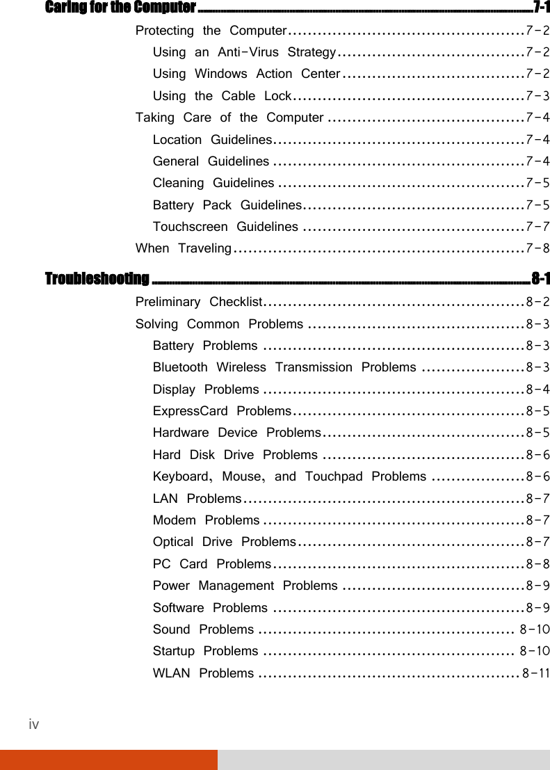
![Using BIOS Setup and System Recovery 5-3 Use the keyboard to move around and make selections. Keyboard information can be found at the bottom of the screen. NOTE: The BIOS Setup Utility screens shown in this chapter are for your reference only. The actual items or settings on your computer may differ. The BIOS Setup Utility program may have been updated after the publication of this manual. The settings you select in your operating system might override similar settings in BIOS Setup Utility. Information Menu The Information menu contains the basic configuration information of the system. There are no user-definable items in this menu. Information Main Advanced Security Boot Exit Serial NO: Processor Info: Installed System Memory: SATA HDD: SATA ODD: ESTAT Port: BIOS Revision: EC Revision: LAN MAC Address: IEEE 1394 GUID: Operating Time: 00000000000000 Intel(R) Core(TM) i7 CPU L620@2.00GHz 2048MB [SAMSUNG HM250HI] 250GB [Optiarc DVD RW AD-7580S] [None] R0.05.070520S R0.06F 00-22-20-0A-54-AE 00-40-D0-01-00-48-1A-F9 52 Hours F1 Help ↑↓ Select Item -/+ Change Values F9 Setup Defaults Esc Exit ←→ Select Menu Enter Select Sub-Menu F10 Save and Exit](https://usermanual.wiki/Getac-Technology/3X03/User-Guide-1432623-Page-99.png)
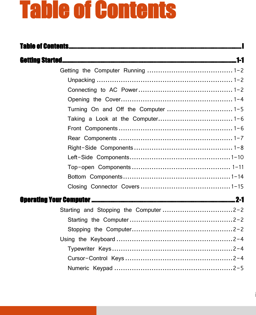
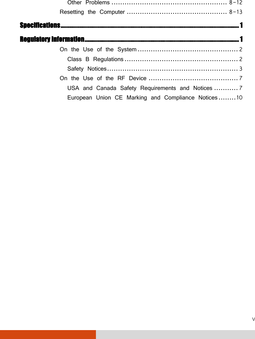
![5-4 Using BIOS Setup and System Recovery Main Menu The Main menu contains the various system settings. Information Main Advanced Security Boot Exit System Time: System Date: Legacy USB Support: Wireless LAN: [ :33:08] [05/14/2010] [Enabled] [Last State] F1 Help ↑↓ Select Item -/+ Change Values F9 Setup Defaults Esc Exit ←→ Select Menu Enter Select Sub-Menu F10 Save and Exit System Time sets the system time. System Date sets the system date. Legacy USB Support enables or disables the system’s support for Legacy USB device in DOS mode. Wireless LAN setting this item to Off will start the system with wireless radio off, On will start the system with the wireless radio on, and Last State will start the system based on the state of wireless radio during your last power off. 11](https://usermanual.wiki/Getac-Technology/3X03/User-Guide-1432623-Page-100.png)
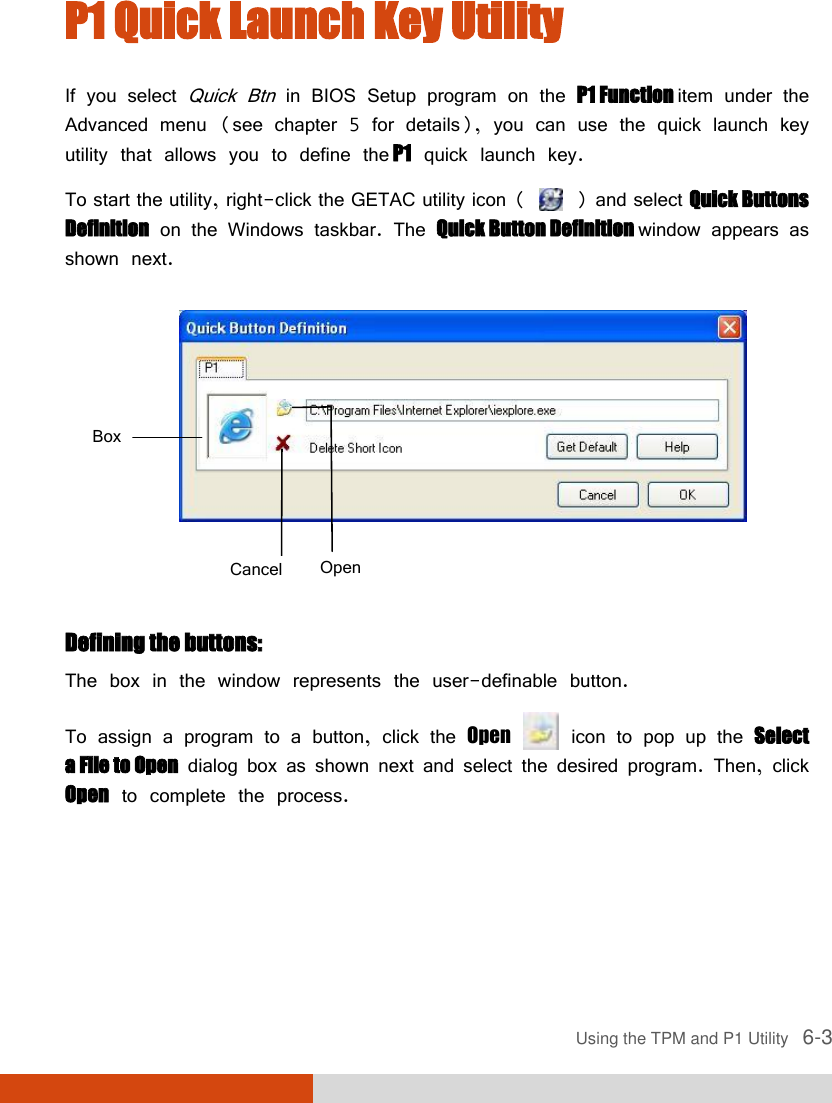
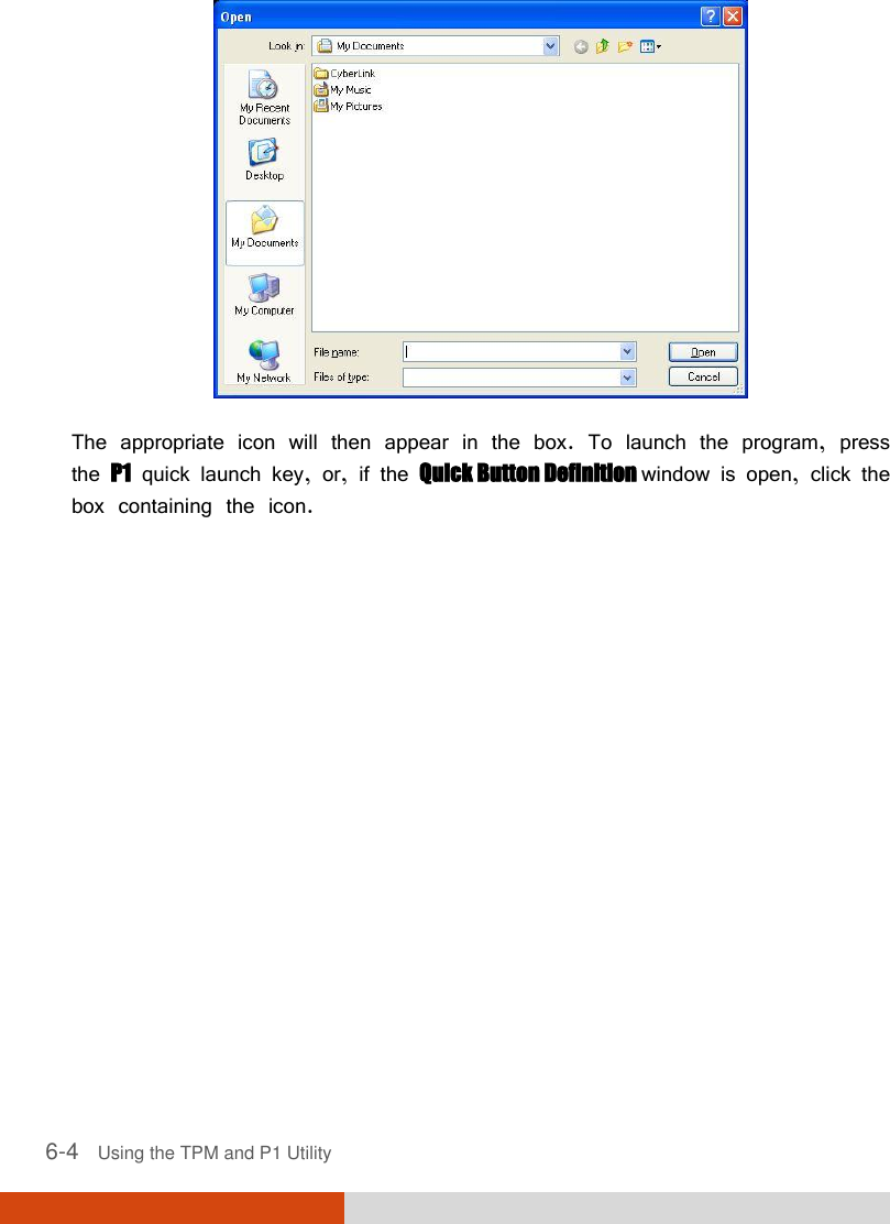
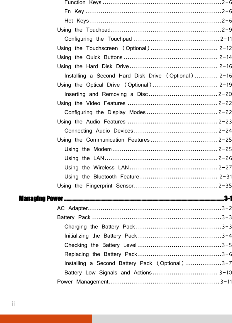
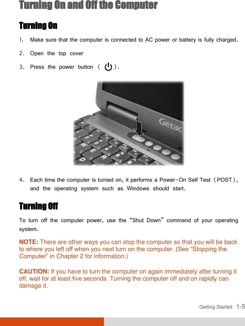
![Using BIOS Setup and System Recovery 5-5 Advanced Menu The Advanced menu contains the advanced settings. Information Main Advanced Security Boot Exit P1 Function: Any-key Wake Up from S3: CD/DVD Auto Power Control: Ring Wake-Up from S3 USB Wake-up from S3 AC Initiation SATA Mode [ ] [Disabled] [Enabled] [Disabled] [Disabled] [Disabled] [AHCI] Item Specific Help Select P1 button act as Blackout ON/OFF , Quick launch button or Emergency button. F1 Help ↑↓ Select Item -/+ Change Values F9 Setup Defaults Esc Exit ←→ Select Menu Enter Select Sub-Menu F10 Save and Exit P1 Function allows you to specify the P1 quick button function. When set at Blackout the P1 quick button allows you to turn off the LCD backlight and LED indicator. When set at Quick Btn the P1 quick button functions as a user customized quick launch key. CD/DVD Auto Power Control allows you to enable the optical drive’s automatic power control when using battery power. Ring Wake-up From S3 allows the system to wake up from Sleep mode via modem. USB Wake-up From S3 allows the system to wake up from Sleep mode via USB device. AC Initiation sets if connecting AC power will automatically start or resume the system. Blackout](https://usermanual.wiki/Getac-Technology/3X03/User-Guide-1432623-Page-101.png)
![5-6 Using BIOS Setup and System Recovery SATA Mode set to AHCI if your hard disk supports AHCI. AHCI allows you to take advantage of Advanced Host Controller Interface features. The options are IDE and AHCI. Security Menu The Security menu contains the security settings, which safeguard your system against unauthorized use. Information Main Advanced Security Boot Exit Set Supervisor Password TPM Setup Menu: Intel Trusted Execution [Enter] [Disabled] Item Specific Help Supervisor Password controls access to the Setup utility. F1 Help ↑↓ Select Item -/+ Change Values F9 Setup Defaults Esc Exit ←→ Select Menu Enter Select Sub-Menu F10 Save and Exit Set Supervisor Password sets the supervisor password. When typing the password, first make sure that Num Lock is off, and then type the password in the entry fields and press Enter. Confirm your password by typing it again and pressing Enter. When set, the supervisor password is required for entering BIOS Setup. Enter](https://usermanual.wiki/Getac-Technology/3X03/User-Guide-1432623-Page-102.png)
![Using BIOS Setup and System Recovery 5-7 TPM Setup Menu Press Enter to display the following screen. TPM Support enables or disables TPM support (see chapter 6 for details). Current TPM State shows the current TPM state. Change TPM State allows you to select between No Change, Clear, Deactivate & Disable, and Enable & Activate. Intel Trusted Execution enables or disables utilization of additional hardware capabilities provided by Intel Trusted Execution Technology. Information Main Advanced Security Boot Exit TPM Setup Menu Item Specific Help TPM Support Current TPM State: Change TPM State [Enter ] Disabled & Deactivated [No Change ] Enable Trusted Platform Module support F1 Help ↑↓ Select Item -/+ Change Values F9 Setup Defaults Esc Exit ←→ Select Menu Enter Select Sub-Menu F10 Save and Exit Enabled](https://usermanual.wiki/Getac-Technology/3X03/User-Guide-1432623-Page-103.png)