Getac Technology S400RFID NOTEBOOK User Manual USERS MANUAL
Getac Technology Corporation NOTEBOOK USERS MANUAL
UserManual.wiki
>
Getac Technology
>
S400RFID User Manual
USERS MANUAL
Navigation menu
Upload a User Manual
Namespaces
Wiki Guide
HTML
PDF
Info
Views
User Manual
Discussion / Help
Navigation


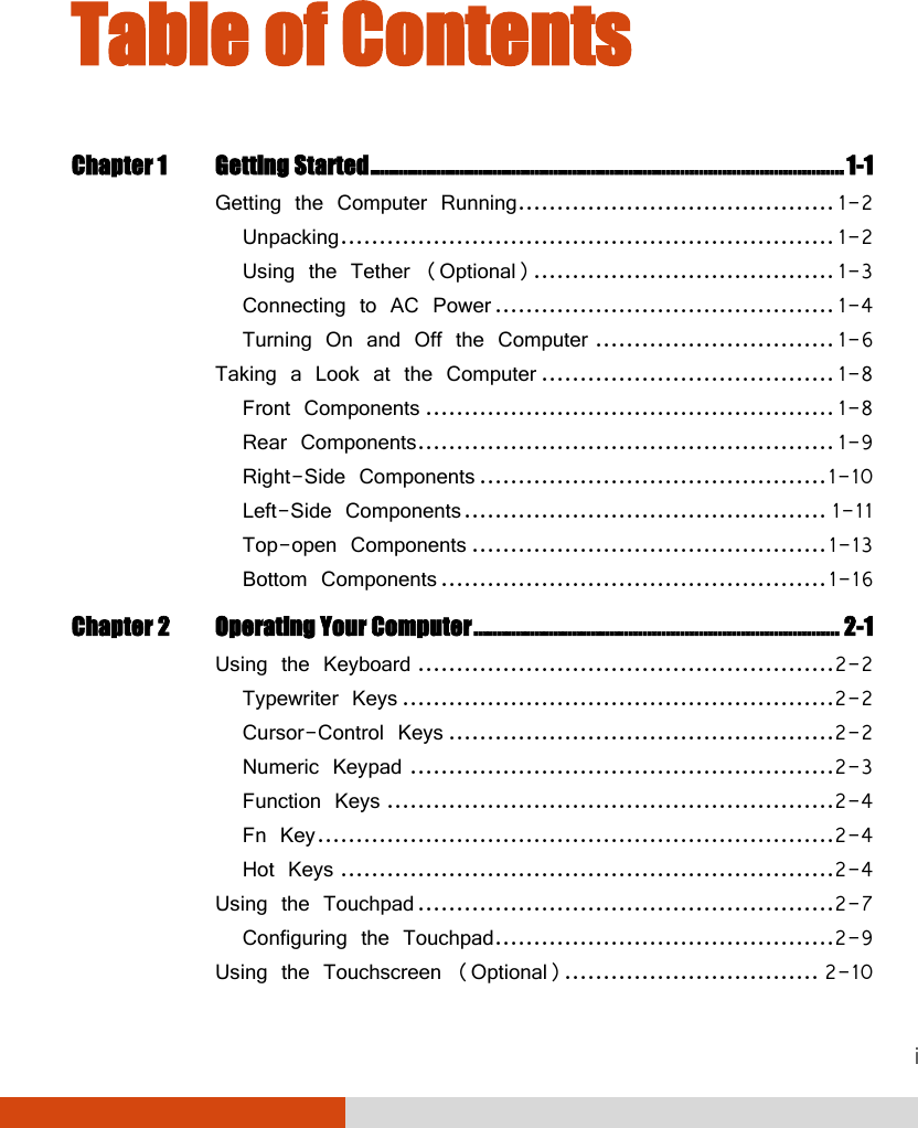


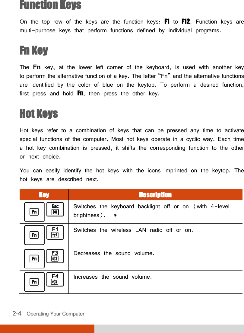

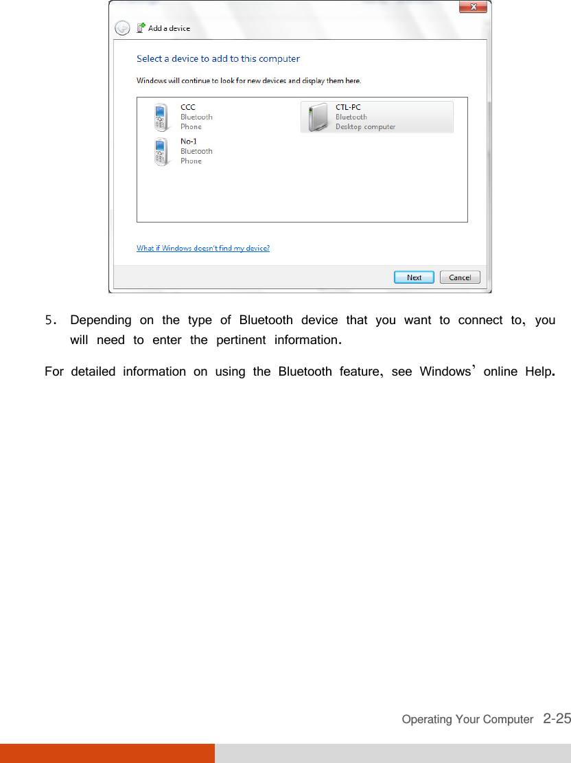


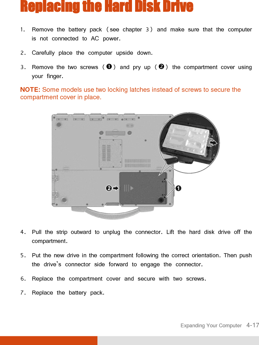
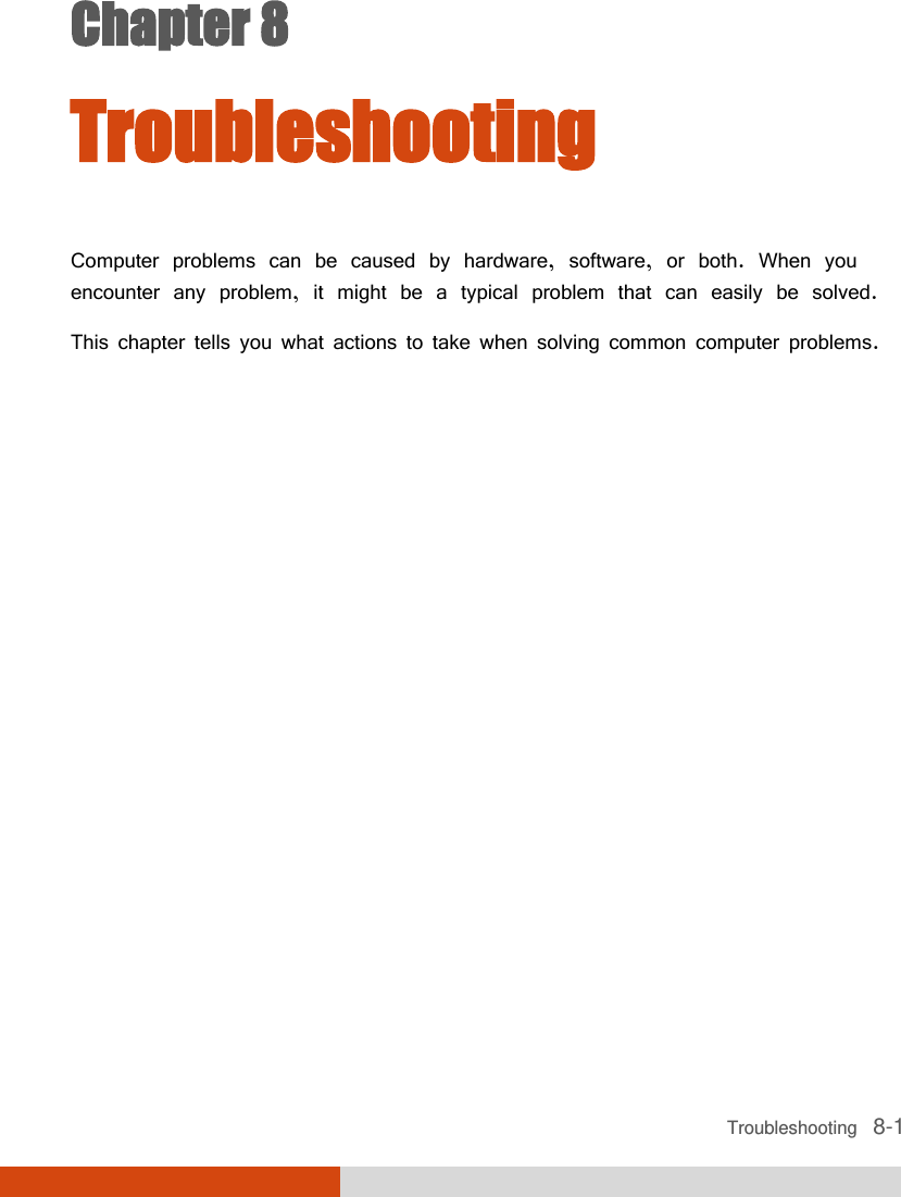
![5-4 Using BIOS Setup and System Recovery Main Menu The Main menu contains the various system settings. Information Main Advanced Security Boot Exit System Date: System Time: Legacy USB Support: Wireless LAN: Bluetooth: [06/29/2012] [11:33:08] [Enabled] [Last State] [Last State] Item Specific Help View or set system date. F1 Help ↑↓ Select Item +/- Change Values F9 Setup Defaults Esc Exit ←→ Select Menu Enter Select Sub-Menu F10 Save and Exit System Date sets the system date. System Time sets the system time. Legacy USB Support enables or disables the system’s support for Legacy USB device in DOS mode. Wireless LAN specifies the on/off state of the wireless LAN radio when the system starts up. When set to Last State, the on/off state remains the same as the last state before you turn off the system. Bluetooth specifies the on/off state of the Bluetooth radio when the system starts up. When set to Last State, the on/off state remains the same as the last state before you turn off the system. 06](https://usermanual.wiki/Getac-Technology/S400RFID/User-Guide-1776588-Page-90.png)
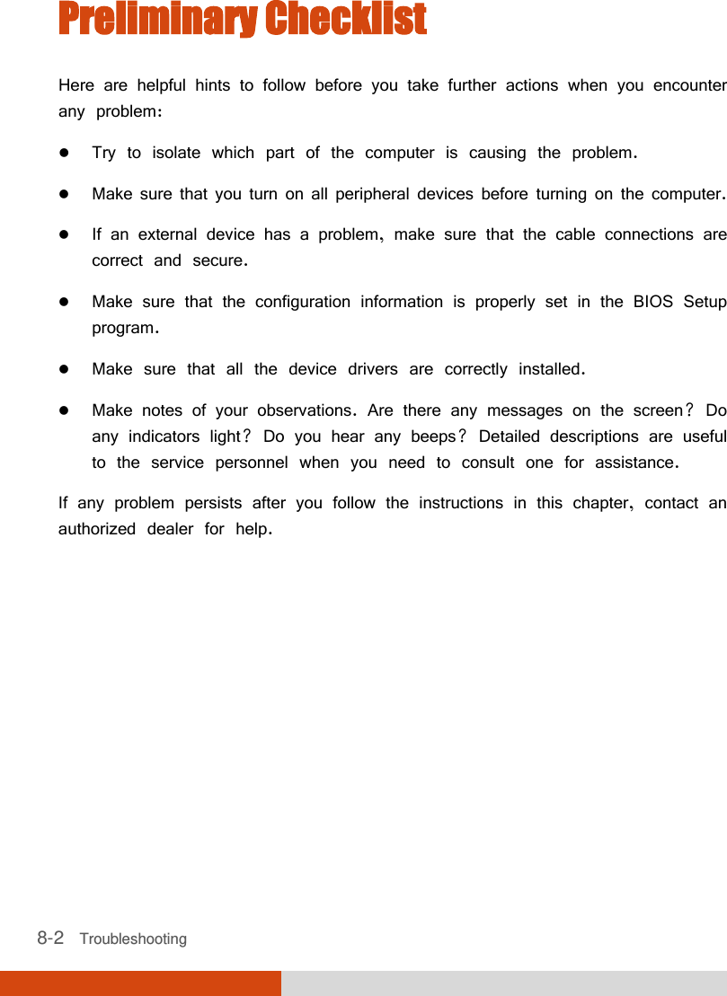
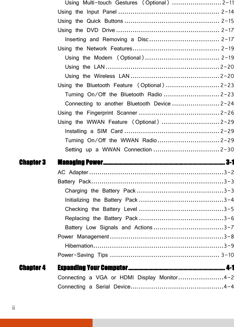
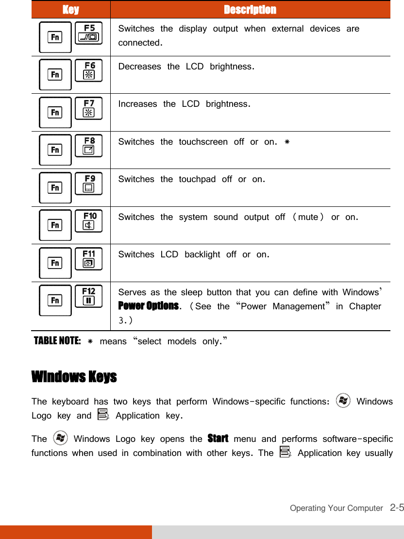
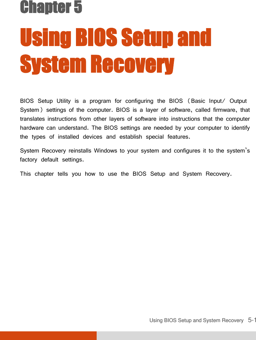
![Using BIOS Setup and System Recovery 5-5 Advanced Menu The Advanced menu contains the advanced settings. Information Main Advanced Security Boot Exit Intel(R) Rapid Start Technology Wake Up Capability AC Initiation: SATA Mode: AMT Configuration Virtualization Technology Setup Graphic Setup Button Setup Device Configuration [Disabled] [AHCI] Item Specific Help iRST – Intel (R) Rapid Start Technology Configuration F1 Help ↑↓ Select Item +/- Change Values F9 Setup Defaults Esc Exit ←→ Select Menu Enter Select Sub-Menu F10 Save and Exit Intel (R) Rapid Start Technology cofigures iRST. Press Enter to access the submenu as shown below. Advanced Intel (R) Rapid Start Technology Item Specific Help iRST Support: [Disabled] Enable iRST. F1 Help ↑↓ Select Item +/- Change Values F9 Setup Defaults Disabled](https://usermanual.wiki/Getac-Technology/S400RFID/User-Guide-1776588-Page-91.png)
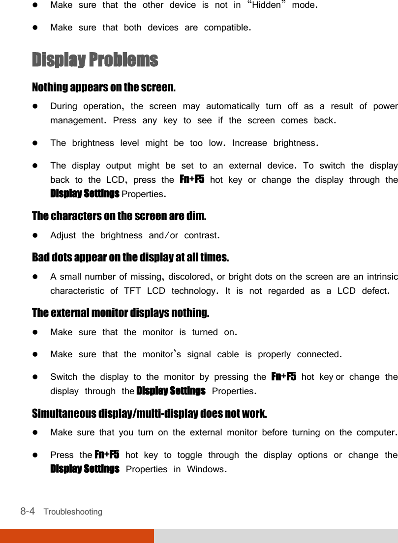
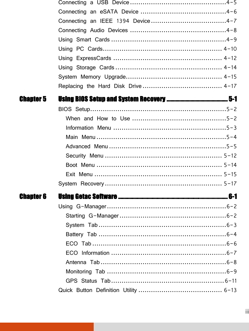
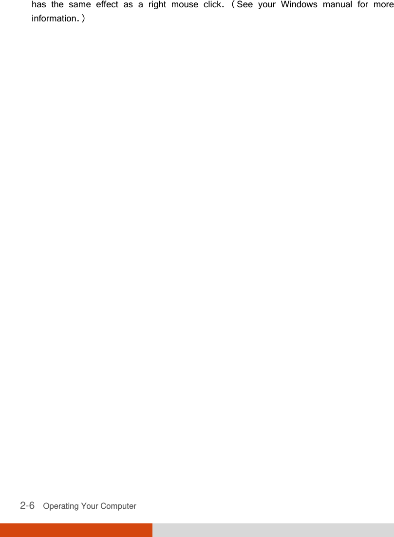
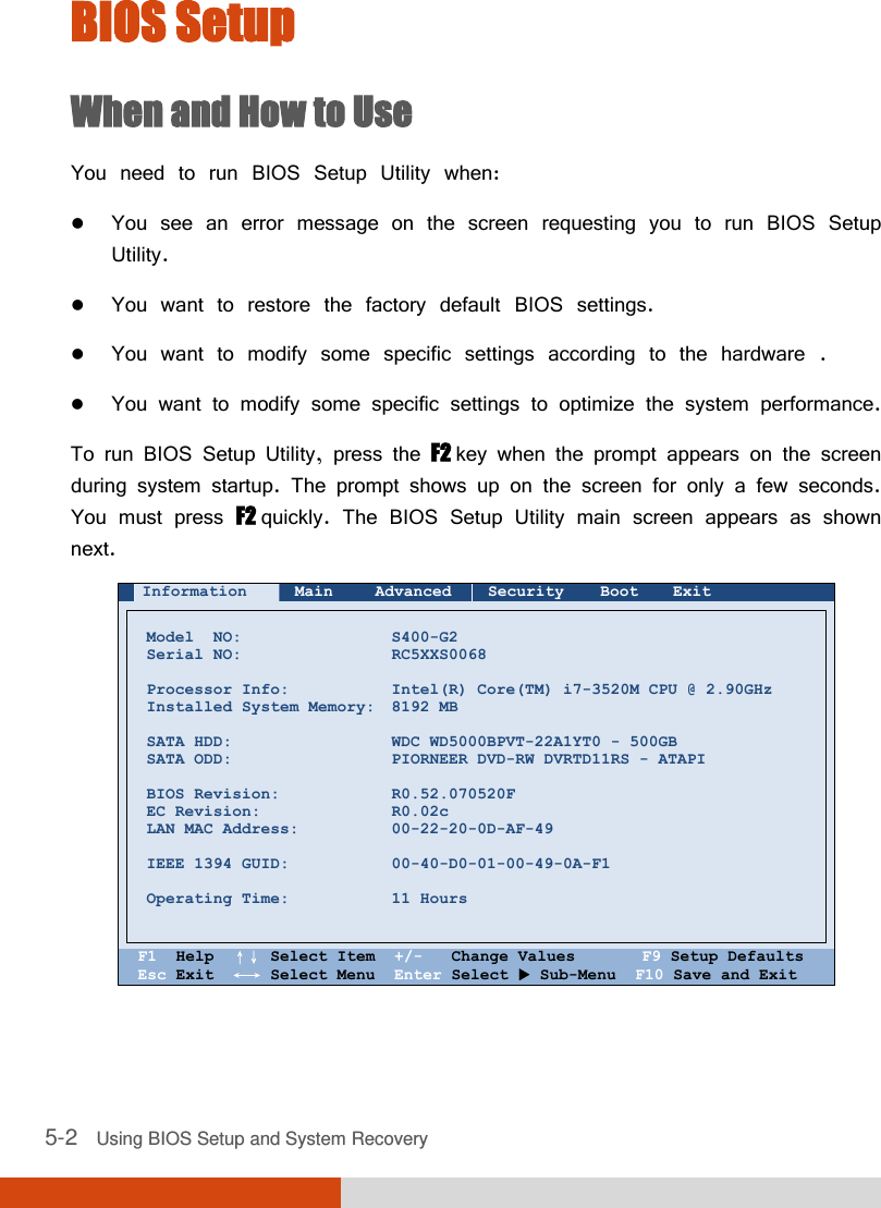
![5-6 Using BIOS Setup and System Recovery Esc Exit ←→ Select Menu Enter Select Sub-Menu F10 Save and Exit iRST Support enables of disables iRST, which gets your system up and running faster. Wake Up Capability specifies events for waking up the system from S3 (Sleep) state. Press Enter to access the submenu as shown below. Advanced Wake Up Capability Item Specific Help Any-key Wake Up From S3: Ring Wake-Up From S3: USB Wake-Up From S3: [Disabled] [Disabled] [Disabled] Allow any key to wake up the system from S3 (Sleep) state. F1 Help ↑↓ Select Item +/- Change Values F9 Setup Defaults Esc Exit ←→ Select Menu Enter Select Sub-Menu F10 Save and Exit Any-key Wake Up From S3 allows any key to wake up the system from S3 (Sleep) state. Ring Wake-Up From S3 allows a modem activity to wake up the system from S3 (Sleep) state. USB Wake-Up From S3 allow a USB device activity to wake up the system from S3 (Sleep) state. (This feature works for Windows 7 only.) AC Initiation sets if connecting AC power will automatically start or resume the system. SATA Mode set to AHCI if your hard disk supports AHCI. AHCI allows you to take advantage of Advanced Host Controller Interface features. The options are IDE and AHCI. Disabled](https://usermanual.wiki/Getac-Technology/S400RFID/User-Guide-1776588-Page-92.png)
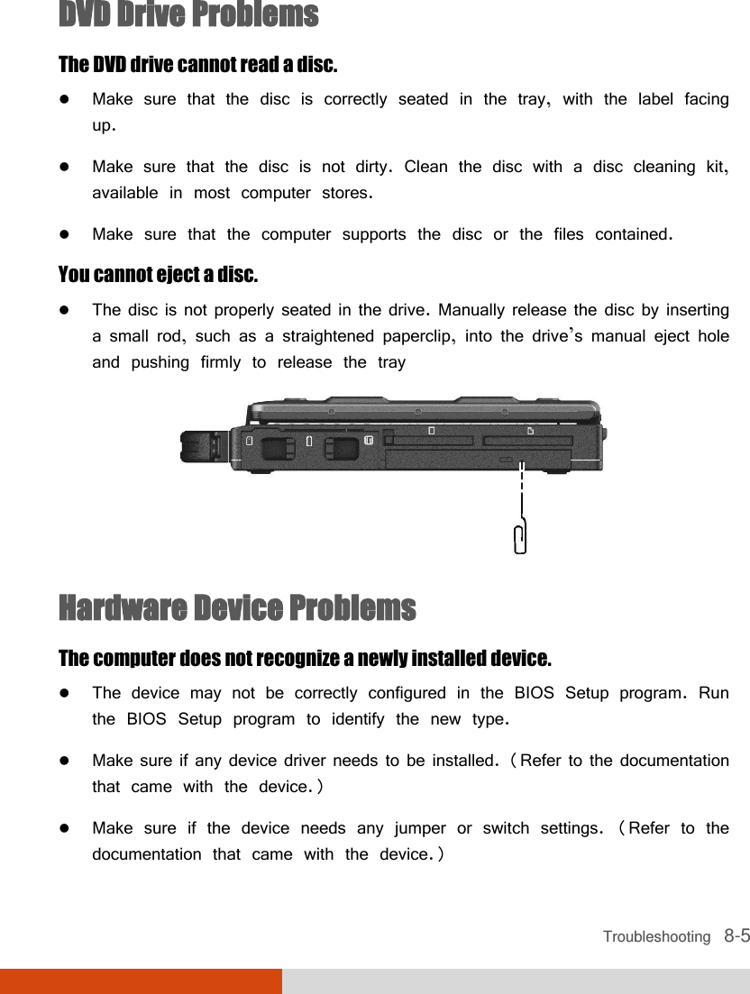
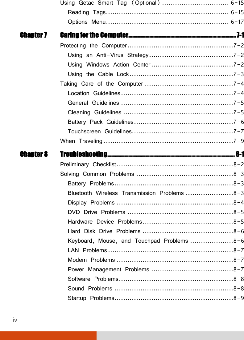
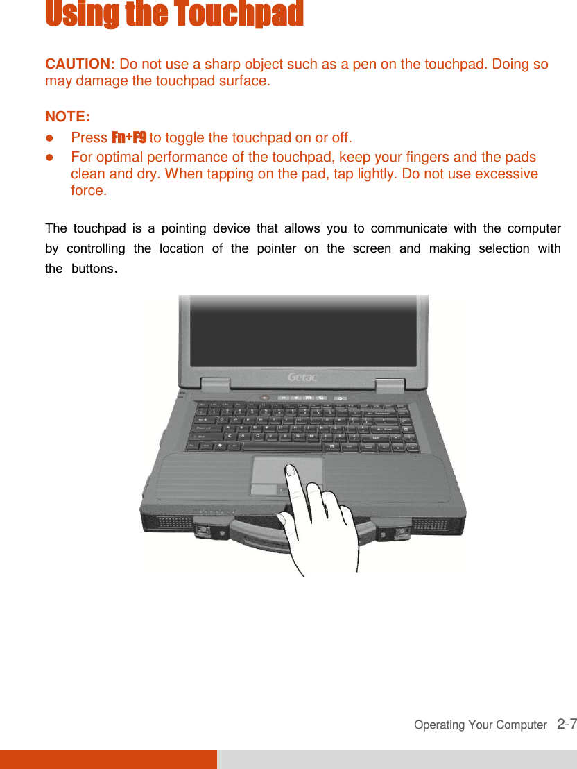
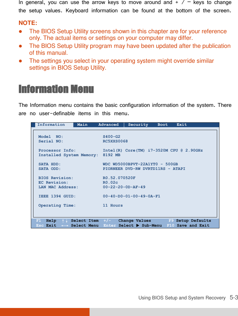
![Using BIOS Setup and System Recovery 5-7 CAUTION: Incorrect SATA mode settings can result in hard disk drive boot failure. AMT Configuration configures Active Management Technology parameters. Press Enter to access the submenu as shown below. Advanced AMT Configuration Item Specific Help Intel AMT: Intel AMT Setup Prompt: [Disabled] [Disabled] Enable/Disable Intel(R) Active Management Technology BIOS Extension. Note: iAMT H/W is always enabled. This option just controls the BIOS extension execution. If enabled this requires additional firmware in the SPI device F1 Help ↑↓ Select Item +/- Change Values F9 Setup Defaults Esc Exit ←→ Select Menu Enter Select Sub-Menu F10 Save and Exit Intel AMT enables or disables Intel® Active Management Technology BIOS extension execution. AMT allows the system administrator to access an AMT featured computer remotely. Intel AMT Setup Prompt determines whether the prompt for entering Intel AMT Setup appears or not during POST. If disabled, users cannot enter Intel AMT Setup. Virtualization Technology Setup sets Virtualization Technology parameters. Press Enter to access the submenu as shown below. Enabled](https://usermanual.wiki/Getac-Technology/S400RFID/User-Guide-1776588-Page-93.png)
![5-8 Using BIOS Setup and System Recovery Advanced Virtualization Technology Setup Item Specific Help Intel(R) Virtualization Technology Intel(R) VT for Directed I/O(VT-d) [Disabled] [Disabled] When enabled, a VMM can utilize the additional hardware virtualization capabilities. F1 Help ↑↓ Select Item +/- Change Values F9 Setup Defaults Esc Exit ←→ Select Menu Enter Select Sub-Menu F10 Save and Exit Intel(R) Virtualization Technology enables or disables Intel® VT (Intel Virtualization Technology) feature which provides hardware support for processor virtualization. When enabled, a VMM (Virtual Machine Monitor) can utilize the additional hardware virtualization capabilities provided by this technology. Intel(R) VT for Directed I/O(VT-d) enables or disables VT-d (Intel® Virtualization Technology for Directed I/O). When enabled, VT-d helps enhance Intel platforms for efficient virtualization of I/O devices. Graphics Setup sets graphics related options. Press Enter to access the submenu as shown below. Disabled](https://usermanual.wiki/Getac-Technology/S400RFID/User-Guide-1776588-Page-94.png)
![Using BIOS Setup and System Recovery 5-9 Advanced Graphic Setup Item Specific Help DVMT Pre-Allocated: Total Graphics Memory: [ ] [256MB] Select Pre-Allocated Graphics Memory size used by the Internal Graphics Device. This has no effect if external graphics are present. F1 Help ↑↓ Select Item -/+ Change Values F9 Setup Defaults Esc Exit ←→ Select Menu Enter Select Sub-Menu F10 Save and Exit NOTE: Graphic Setup parameters apply to the internal graphics device only. DVMT Pre-Allocated sets the amount of pre-allocated (fixed) graphics memory for use by the internal graphics device. Total Graphics Memory sets the amount of total graphics memory (pre-allocated + fixed + DVMT) for use by the internal graphics device. Button Setup sets hardware button related options. Press Enter to access the submenu as shown below. 64MB](https://usermanual.wiki/Getac-Technology/S400RFID/User-Guide-1776588-Page-95.png)
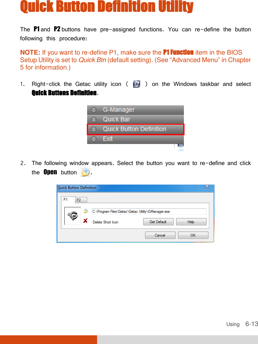
![5-10 Using BIOS Setup and System Recovery Information Main Advanced Security Boot Exit Button Setup: Item Specific Help P1 Function: [Disable d] Define P1 button as Quick launch button or Emergency button. F1 Help ↑↓ Select Item +/- Change Values F9 Setup Defaults Esc Exit ←→ Select Menu Enter Select Sub-Menu F10 Save and Exit P1 Function specifies the P1 quick button function. When set to Quick Btn, the P1 quick button serves as a user-defined quick launch key. When set to Emergency Btn, the P1 quick button serves as the Emergency button. “Emergency button” only works with customized applications that support the specific button. HDD Preheat keeps the hard disk drive’s temperature above 5oC (41oF) during system shutdown period as long as external AC power is connected. When set to Enabled, the optional heater will automatically turn on if the hard disk drive’s temperature drops below 5oC (41oF). (The availability of this item depends on your model.) Quick Btn](https://usermanual.wiki/Getac-Technology/S400RFID/User-Guide-1776588-Page-96.png)
![Using BIOS Setup and System Recovery 5-11 Device Configuration enables or disables several hardware components. Press Enter to access the submenu as shown below. Advanced Device Configuration Item Specific Help Wireless LAN: WWAN: Bluetooth: Media Card Reader: Smart Card Reader: HD Audio: Modem: Fingerprint Scanner: 1394 Port: E-SATA Port: [ ] [Enabled] [Enabled] [Enabled] [Enabled] [Enabled] [Enabled] [Enabled] [Enabled] [Enabled] Set WLAN device to enable/disable. F1 Help ↑↓ Select Item +/- Change Values F9 Setup Defaults Esc Exit ←→ Select Menu Enter Select Sub-Menu F10 Save and Exit You can enable or disable the following items: Wireless LAN WWAN Bluetooth Media Card Reader (MMC/SD) Smart Card Reader HD Audio (High Definition Audio) Modem Fingerprint Scanner Enabled](https://usermanual.wiki/Getac-Technology/S400RFID/User-Guide-1776588-Page-97.png)
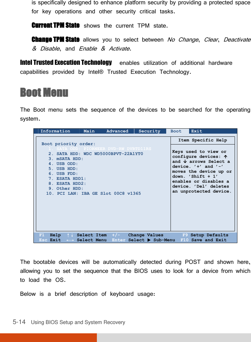
![5-12 Using BIOS Setup and System Recovery 1394 Port E-SATA Port Security Menu The Security menu contains the security settings, which safeguard your system against unauthorized use. Information Main Advanced Security Boot Exit Supervisor Password Is: User Password Is: Set Supervisor Password: Set User Password Password on Boot: Set HDD 0 Password: HDD 0 Password: TPM Setup Menu Intel Trusted Execution Technology Cleared Cleared [Enter] [Enter] [Disabled] [Enter] Cleared [Disabled] Item Specific Help Set or clear the Supervisor account’s password. F1 Help ↑↓ Select Item +/- Change Values F9 Setup Defaults Esc Exit ←→ Select Menu Enter Select Sub-Menu F10 Save and Exit NOTE: You can set the user password only when the supervisor password has been set. If both the administrator and user passwords are set, you can enter any of them for starting up the system and/or entering BIOS Setup. However, the user password only allows you to view/change the settings of certain items. A password setting is applied right after it is confirmed. To cancel a password, leave the password empty by pressing the Enter key. Supervisor/User Password Is shows whether you have set the supervisor/user password or not for the system. Enter](https://usermanual.wiki/Getac-Technology/S400RFID/User-Guide-1776588-Page-98.png)
![Using BIOS Setup and System Recovery 5-13 Set Supervisor/User Password sets the supervisor/user password. When typing the password, first make sure that Num Lock is off, and then type the password in the entry fields and press Enter. Confirm your password by typing it again and pressing Enter. You can set the supervisor/user password to be required for starting up the system and/or entering BIOS Setup. Password on Boot allows you to enable or disable the entering of password for booting up your system. Once the password is successfully set and this item is enabled, it is required for booting up the system. Set HDD 0 Password sets the password for locking the Primary Master hard disk drive. After setting a password, the hard disk drive can only be unlocked by the password no matter where it is installed. HDD 0 Password Is shows whether you have set the hard disk password or not. TPM Setup Menu sets various TPM parameters. Press Enter to access the submenu as shown below. TPM Support enables or disables TPM (Trusted Platform Module) support. TPM (Trusted Platform Module) is a component on your computer’s mainboard that Security TPM Setup Menu Item Specific Help TPM Support: Current TPM State: Change TPM Status: [ ] [Disabled and Deactivated] [No Change] This is used to decide whether TPM support should be enabled or disabled. F1 Help ↑↓ Select Item +/- Change Values F9 Setup Defaults Esc Exit ←→ Select Menu Enter Select Sub-Menu F10 Save and Exit Enabled](https://usermanual.wiki/Getac-Technology/S400RFID/User-Guide-1776588-Page-99.png)