Gilbarco GBIR15 RFID Reader User Manual MDE 4544 Draft
Gilbarco Inc. RFID Reader MDE 4544 Draft
Gilbarco >
User Manual

MDE-4544 Encore S Series TRIND Retrofit Kit C00011-011 Installation Manual • January 2006 Page 1
Draft
Introduction
Purpose
This manual provides instructions for installing the TRIND® C00011-011 Retrofit Kit into
Encore® S Series™ units that contain the CRIND® device.
The Transmitter/Receiver In Dispenser (TRIND) option allows customers to automatically
authorize Card Reader In Dispenser (CRIND) device-equipped units using a hand-held low
frequency transponder tags provided by a Major Oil Company (MOC) or retailer. Use this kit
for one or two-sided unit.
Important Notice
This equipment has been tested and found to comply with the limits for a Class A digital
device pursuant to Part 15 of the Federal Communications Commission (FCC) Rules. These
limits are designed to provide reasonable protection against harmful interference when the
equipment is operated in a commercial environment. This equipment generates, uses and can
radiate radio frequency energy, and if not installed and used in accordance with the instruction
manual, may cause harmful interference to radio communications. Operation of this
equipment in a residential area may cause harmful interference in which case the user will be
required to correct the interference at his own expense. Changes or modifications not
expressly approved by the manufacturer could void the user’s authority to operate this
equipment.
The long term characteristics or the possible physiological effects of radio frequency
electromagnetic fields have not yet been investigated by Underwriters’ Laboratories,
Incorporated (UL®).
Required Reading
Before installing the equipment, the installer must read, understand, and follow:
• this manual
• National Fire Protection Agency (NFPA) 30A, The Automotive and Marine Service
Station Code
• NFPA 70, The National Electric Code
• applicable federal, state and local codes and regulations
Failure to do so may adversely effect the safe use and operation of the equipment.
Note: This kit must be installed by a Gilbarco Authorized Service Contractor (ASC)
MDE-4544
Encore S Series TRIND
Retrofit Kit C00011-011 Installation Manual
January 2006

Introduction
Page 2 MDE-4544 Encore S Series TRIND Retrofit Kit C00011-011 Installation Manual • January 2006
Draft
Related Documents
Document
Number Description GOLD Library
MDE-3804 Encore and Eclipse Series Start-Up/Service Manual Encore and Eclipse
MDE-4516 Encore S Series Owners Manual Encore and Eclipse
MDE-3664 TRIND Start-Up, Service, and Parts Manual CRIND and TRIND
PT-1936 Encore Illustrated Parts Manual Parts Manual
PT-1736 CRIND Card Reader Illustrated Parts Manual Parts Manual
Recommended Tools
The following equipment is needed to install TRIND kit M02112K00X:
• clean cloth or rag
• isopropyl alcohol (part number END-1082)
• nut drivers, metric
• nut drives, standard
• multimeter
• needle nose pliers
• pliers
• pocket knife
• putty knife or scraper
• Diagnostic Card Q12534-170
• ratchet set, metric
• ratchet set, standard
• screwdrivers, flat and Phillips head
• static guard wrist strap
• TRIND ASC tool kit K94577-02 (refer to MDE-3640 ASC TRIND Installation Tool Kit)

MDE-4544 Encore S Series TRIND Retrofit Kit C00011-011 Installation Manual • January 2006 Page 3
Parts Lists
Draft
Parts Lists
TRIND Retrofit Kit C00011-011 Parts List
The following section provide the parts lists for kit C00011-011. The kit is designed for a dual-
sided unit.
Description Part Number Quantity
Assembly, TRIND Electronics M06380A001 1
Assembly, Light and Inductor M06143A00X (see note 1)
Cable Group: Q13863-12 1
• TRIND Door Cable (Side 1) M00507A001 1
• TRIND Door Cable (Side 2) M00507A002 1
• Cable, TRIND Gateway to CCN M00515A002 1
• Cable, TRIND Option Door Data and Power R20773-G1 2
• Cable, TRIND Power Enhanced Encore M06525A001 1
Graphics (Envelope) T18832-01 1
Jumper, 0.100 Centers Q11011-01 10
Kit, Encore S Parts: K96646-04 -
• Window, TRIND Display M05987B001 1
Kit, TRIND Encore Component Parts: M02183K001 -
• Cable Mount, Adhesive Q13558-04 16
• Screw, Self-Tapping Hex Q11677-23 6
•Tie, Cable Q10178-01 4
Label, Patent and FCC M02962B007 1
Notes:
1. Part M06143A00X is a customer specific order entry item (A001 is red, A002 is orange).
2. Part M06525A001 is a customer specific order entry item (based on site survey data).
ASC TRIND Tool Kit K94577-02
The following section provide the lists the parts for ASC TRIND Tool Kit K94577-02. The
ASC TRIND Tool kit is a separate order entry item and is not included with the retrofit kit.
Description Part Number Quantity
Tool Kit, ASC TRIND K94577-02 -
• cable, standalone jumper R20602-G2 1
• test tag, TI/RFID hand held Q13630-02 1
Important Safety Information
Page 4 MDE-4544 Encore S Series TRIND Retrofit Kit C00011-011 Installation Manual • January 2006
Draft
Important Safety Information
This section introduces the hazards and safety precautions associated with installing,
inspecting, maintaining or servicing this product. Before performing any task on this product,
read this safety information and the applicable sections in this manual, where additional
hazards and safety precautions for your task will be found. Fire, explosion, electrical shock or
pressure release could occur and cause death or serious injury if these safe service procedures
are not followed.
Preliminary Precautions
You are working in a potentially dangerous environment of flammable fuels, vapors, and high
voltage or pressures. Only trained or authorized individuals knowledgeable in the related
procedures should install, inspect, maintain or service this equipment.
The first and most important information you must know is how to stop all fuel flow to the
pump and island.
Emergency Total Electrical Shut-Off
Locate the switch or circuit breakers that shut-off all power to all fueling equipment,
dispensing devices, and submerged turbine pumps (STPs). These you must operate in the
event of an emergency.
The EMERGENCY STOP, ALL STOP, and PUMP STOP buttons at the cashier’s
station WILL NOT shut off electrical power to the pump/dispenser.
This means that even if you activate these stops, fuel may continue to flow uncontrolled.
You must use the TOTAL ELECTRICAL SHUT-OFF in the case of an emergency and
not only these cashier station “stops.”
WARNING
!
Total Electrical Shut-Off Before Access
Any procedure requiring access to electrical components or the electronics of the dispenser
requires total electrical shut-off of that unit.
NFPA 30A, Section 4-1.2, published by the National Fire Protection Association, requires the
installation of an easily accessible switch or circuit breaker to shut-off the power to all fueling
equipment, dispensing devices and STPs in the event of an emergency. Know the function and
location of this switch or circuit breaker before inspecting, installing, maintaining, or servicing
Gilbarco equipment.
MDE-4544 Encore S Series TRIND Retrofit Kit C00011-011 Installation Manual • January 2006 Page 5
Important Safety Information
Draft
Evacuation, Barricading and Shut-Off
Any procedures requiring accessing the pump/dispenser or STPs requires the following three
actions:
• An evacuation of all unauthorized persons and vehicles
• Using safety tape or cones as barricades to the effected units
• A total electrical shut-off of that unit
Read the Manual
Read, understand and follow this manual and any other labels or related materials supplied
with this equipment. If you do not understand a procedure, call a Gilbarco Authorized Service
Contractor or call the Gilbarco Call Center at 1-800-800-7498. It is imperative to your safety
and the safety of others to understand the procedures before beginning work.
Follow the Regulations
There is applicable information in: NFPA 30A: Automotive and Marine Service Code; NFPA
70: National Electrical Code (NEC); OSHA regulations; and federal, state, and local codes
which must be followed. Failure to install, inspect, maintain or service this equipment in
accordance with these codes, regulations and standards may lead to legal citations with
penalties or affect the safe use and operation of the equipment.
Safety Symbols and Warning Words
This section provides important information about warning symbols and boxes.
Alert Symbol
This safety alert symbol is used in this manual and on warning labels to alert you to
a precaution which must be followed to prevent potential personal safety hazards. Obey safety
directives that follow this symbol to avoid possible injury or death.
Important Safety Information
Page 6 MDE-4544 Encore S Series TRIND Retrofit Kit C00011-011 Installation Manual • January 2006
Draft
Signal Words
These signal words used in this manual and on warning labels tell you the seriousness of
particular safety hazards. The precautions that follow must be followed to prevent death,
injury or damage to the equipment.
This signal word designates a hazard or unsafe practice which may result in minor injury.
This signal word is used to alert you to a hazard or unsafe practice which will result in death or
serious injury.
This alerts you to a hazard or unsafe practice that could result in death or serious injury.
CAUTION
When used by itself, CAUTION designates a hazard or unsafe practice which may result in
property or equipment damage.
CAUTION
DANGER
WARNING
!
!
!
Prevent Explosions and Fires
Fuels and their vapors will become explosive if ignited. Spilled or leaking fuels cause vapors.
Even filling customer tanks will cause explosive vapors in the vicinity of dispenser or island.
No Open Flames
Open flames from matches, lighters, welding torches or other sources can ignite
fuels and their vapors.
No Sparks - No Smoking
Sparks from starting vehicles, starting or using power tools, burning cigarettes,
cigars or pipes can also ignite fuels and their vapors. Static electricity, including an
electrostatic charge on your body, can cause a spark sufficient to ignite fuels and their vapors.
After getting out of a vehicle, touch the metal of your vehicle to discharge any electrostatic
charge before you approach the dispenser island.

MDE-4544 Encore S Series TRIND Retrofit Kit C00011-011 Installation Manual • January 2006 Page 7
Important Safety Information
Draft
Other Useful Safety Information
This subsection provides additional safety information.
OSHA Lock-Out and Tag-Out Requirements
OSHA Standard 29 CFR 1910-147 Control of Hazardous Energy Sources (Lock-Out/Tag-Out)
covers ways to avoid personal injury because power was turned on or fuel pressure was
applied unexpectedly while servicing equipment. The rule requires:
(1) Turning off equipment power and fuel under pressure.
(2) Use of a locking device (breaker, valve, etc.) or label device with a warning tag.
Station employees and service contractors need to understand and comply with this program
completely to ensure safety while the equipment is down.
Use Electrostatic Discharge Precautions
Place yourself at a neutral static-free potential by doing the following:
1Touch an unpainted metal surface.
2 Use a wrist strap connected to a grounded metal frame or chassis.
3Make sure all power has been removed from unit and the CRIND device.
Installation
Page 8 MDE-4544 Encore S Series TRIND Retrofit Kit C00011-011 Installation Manual • January 2006
Draft
Installation
Perform the following procedures to install TRIND Retrofit Kit C00011-011. The installation
procedures for this manual consists of the following sections:
•Addressing the Gateway Board
•Installing the Enhanced Gateway Board (TRIND Electronics - M06380A001)
•Installing Light and Inductor Assembly M06143A00X
•Routing Cables
•TRIND Cable Block Diagram R20775, Sheet 2
•Enabling the TRIND Device and Verifying Addresses
•Testing the TRIND Device
•Completing Installation
Addressing the Gateway Board
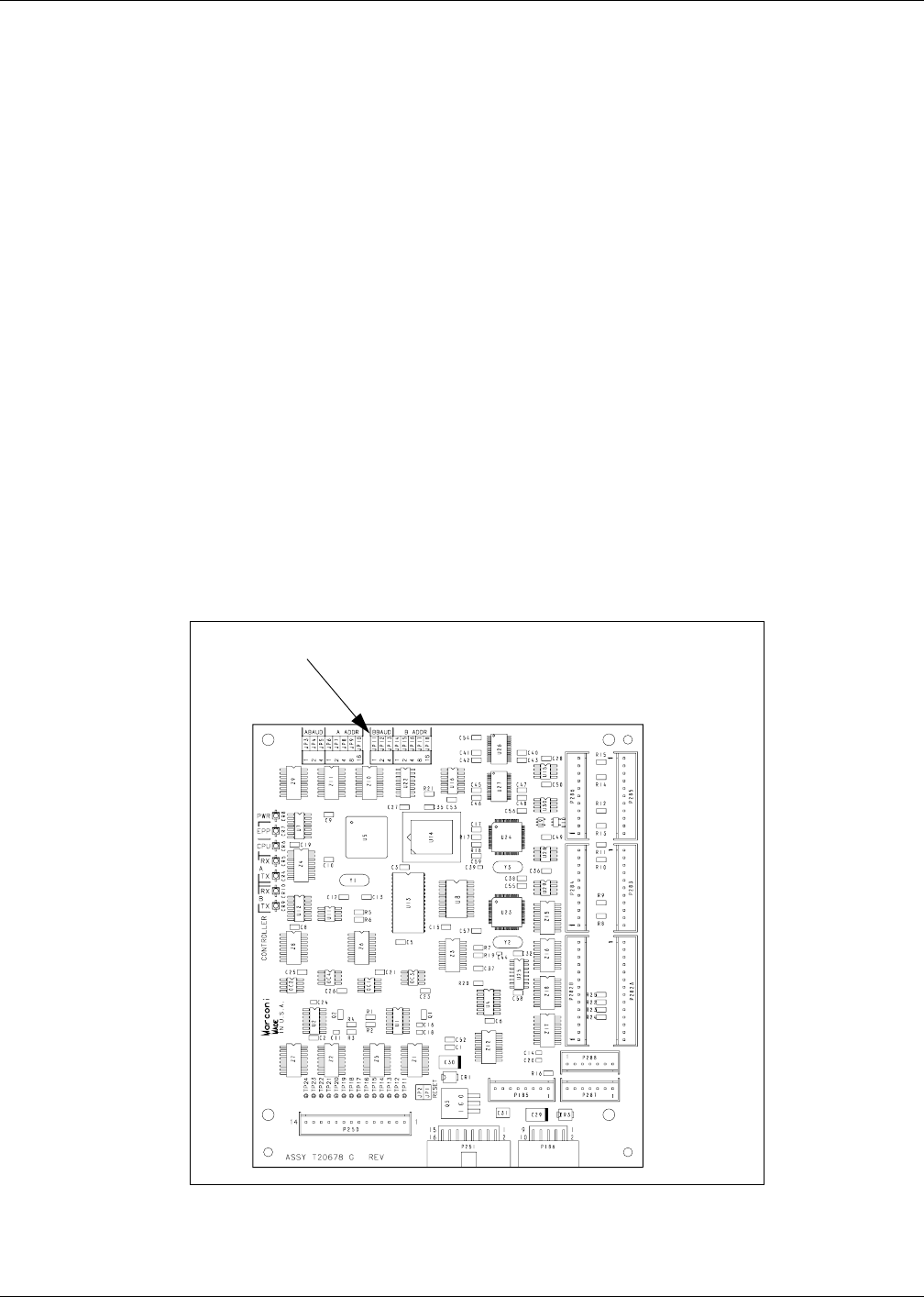
The jump jacks on Gateway Board T20678-GX (Figure 1) are easier to set prior to installing
the Card Cage Assembly into the dispenser. Complete the following procedures to setup
addresses on the Gateway Board. The Gateway Board contains jump jacks that are used to
setup addresses that will match addresses set in software on CRIND Control Node PCA
M00089. Perform the following steps to setup addresses on the Gateway Board.
Figure 1: Gateway Board T20678-GX Jump Jack Location
Jump jack locations on
Gateway Board

MDE-4544 Encore S Series TRIND Retrofit Kit C00011-011 Installation Manual • January 2006 Page 9
Installation
Draft
1Set the jump jacks (Figure 1) on Gateway Board T20678-GX to match the CRIND addresses
of the fueling unit subject to TRIND installation. Refer to the following table for the jack
settings that correspond to a CRIND address.
Note: For generic CRIND, address the Gateway Board to correspond with the proper CRIND
address. This should be done in accordance with Site Controller requirements.
MOC Encore CRIND Addresses Jack Settings
Side 1 = Address on Gateway Board T20678 ‘A’ Side JP6 JP7 JP8 JP9 JP10
Side 2 = Address on Gateway Board T20678 ‘B’ Side JP14 JP15 JP16 JP17 JP18
1IN OUT OUT OUT OUT
2OUT IN OUT OUT OUT
3IN IN OUT OUT OUT
4OUT OUT IN OUT OUT
5IN OUT IN OUT OUT
6OUT IN IN OUT OUT
7IN IN IN OUT OUT
8OUT OUT OUT IN OUT
9IN OUT OUT IN OUT
10 OUT IN OUT IN OUT
11 IN IN OUT IN OUT
12 OUT OUT IN IN OUT
13 IN OUT IN IN OUT
14 OUT IN IN IN OUT
15 IN IN IN IN OUT
16 OUT OUT OUT OUT IN
17 IN OUT OUT OUT IN
18 OUT IN OUT OUT IN
19 IN IN OUT OUT IN
20 OUT OUT IN OUT IN
21 IN OUT IN OUT IN
22 OUT IN IN OUT IN
23 IN IN IN OUT IN
24 OUT OUT OUT IN IN
25 IN OUT OUT IN IN
26 OUT IN OUT IN IN
27 IN IN OUT IN IN
28 OUT OUT IN IN IN
29 IN OUT IN IN IN
30 OUT IN IN IN IN
31 IN IN IN IN IN
32 OUT OUT OUT OUT OUT

Installation
Page 10 MDE-4544 Encore S Series TRIND Retrofit Kit C00011-011 Installation Manual • January 2006
Draft
Installing the Enhanced Gateway Board (TRIND Electronics - M06380A001)
Install the enhanced gateway board assembly from Side 2 of the unit according to the
following steps:
1Place the assembly on the shelf provided, aligning four studs on underside of card cage with
holes provided on shelf.
2Secure assembly to shelf using three (3) nuts (M00414B005) with external lock washers
provided with kit.
Installing Light and Inductor Assembly M06143A00X
Perform the following steps to install Light and Inductor Assembly M06143A00X.
1 Install M06143A00X to Encore S bezel using three (3) screws (Q11677-24) provided.
2Repeat step 1 for the other side bezel.
Routing Cables
Perform the following steps to install retrofit kit cables. Refer to “TRIND Cable Block
Diagram R20775, Sheet 2” on page 13 for details on making connections.
1Obtain AC Power Cable M06525A001 from the kit.
2 Locate the M00806A00X AC Power Distribution Cable inside the electronics cabinet of the
dispenser. Attach plug P1 of AC Power Cable M06525A001 to one of the AC taps on AC
Power Distribution Cable M00806A00X .
3 Attach the ground connection of AC Power Cable M06525A001 to a convenient chassis
ground.
4Obtain Light/Multi-Protocol Cable R20773-G1 from the kit and connect the J182 end of the
cable to P182 on Light Board Assembly M06143A001.
5Secure the R20773-G1 Cable to door, and route and feed the other cables.
6For both CIM Doors, use cable clamps to route cables to and along the door.
Note: Be sure that the cables are secured with sufficient slack to allow door to open and close
without pinching the cabling.
7Connect the J1/J2 end of the R20773-GX cable to P2 end of the M00507A00X Ribbon Cable
extending from the Card Cage Assembly .
MDE-4544 Encore S Series TRIND Retrofit Kit C00011-011 Installation Manual • January 2006 Page 11
Installation
Draft
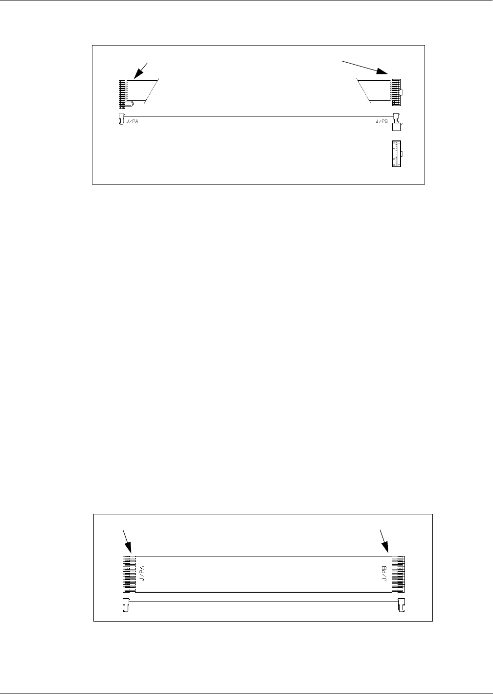
Figure 2: M00507A00X Ribbon Cable
J282A/J282B P1/P2
8Obtain Light/Multi-Protocol Cable R20773-G1 from the kit and connect the J182 end of the
cable to P182 on the Light Board Assembly M06143A00X.
9Secure the R20773-G1 Cable to the door and route the cable through the bezel.
10 Feed cables into the CIM door.
11 Use the cable clamps to route the cables to and along the door.
Note: Be sure that cables are secured with sufficient slack to allow door to open and close
without pinching the cabling.
12 Connect the J1/J2 end of the R20773-G1 cable to the P1 end of the M00507A00X Ribbon
Cable extending from the Card Cage Assembly.
13 Obtain TRIND Gateway Ribbon Cable M00515A00X from the kit and perform the following
to connect Enhanced Gateway Board T20678-GX to CRIND Control Node Printed Circuit
Assembly M00089A00X :
• Connect J250 on gateway cable M00515A00X to plug P250 on Enhanced Gateway Board
T20678-GX
• Connect J3110 on gateway cable M00515A00X to plug P3110 on CRIND Control Node
PCA.
Figure 3: TRIND Gateway 14 Position Ribbon Cable M00515A00X
J3110 J250
Installation
Page 12 MDE-4544 Encore S Series TRIND Retrofit Kit C00011-011 Installation Manual • January 2006
Draft
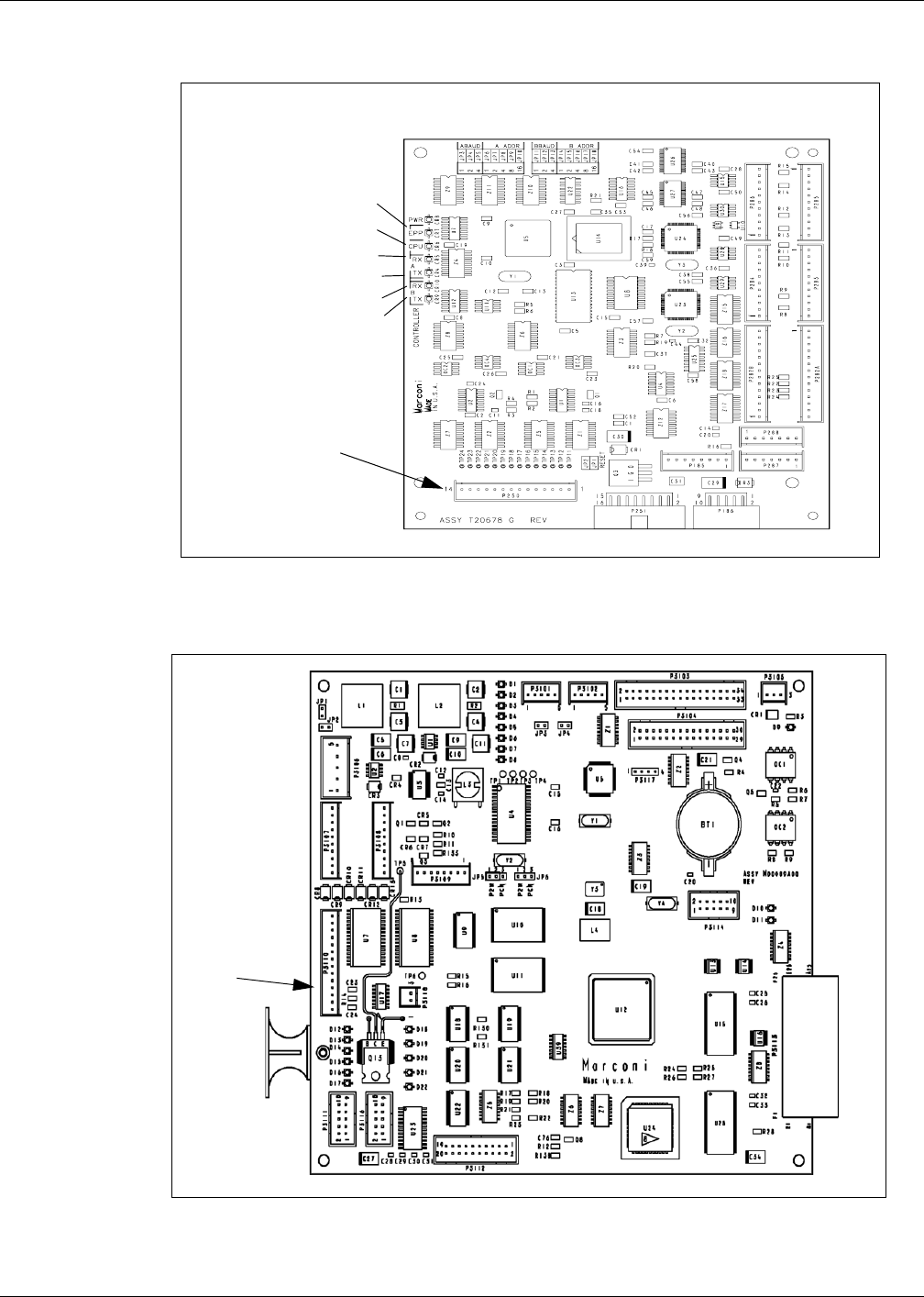
Figure 4: Enhanced Gateway Printed Circuit Board Assembly T20678-GX
CPU = Software Running
PWR = 5V
RX = From A Side CRIND
TX = To A Side CRIND
RX = From B Side CRIND
TX = To B Side CRIND
P250
Figure 5: CRIND Control Node PCA M00089A00X
P3110
MDE-4544 Encore S Series TRIND Retrofit Kit C00011-011 Installation Manual • January 2006 Page 13
Installation
Draft
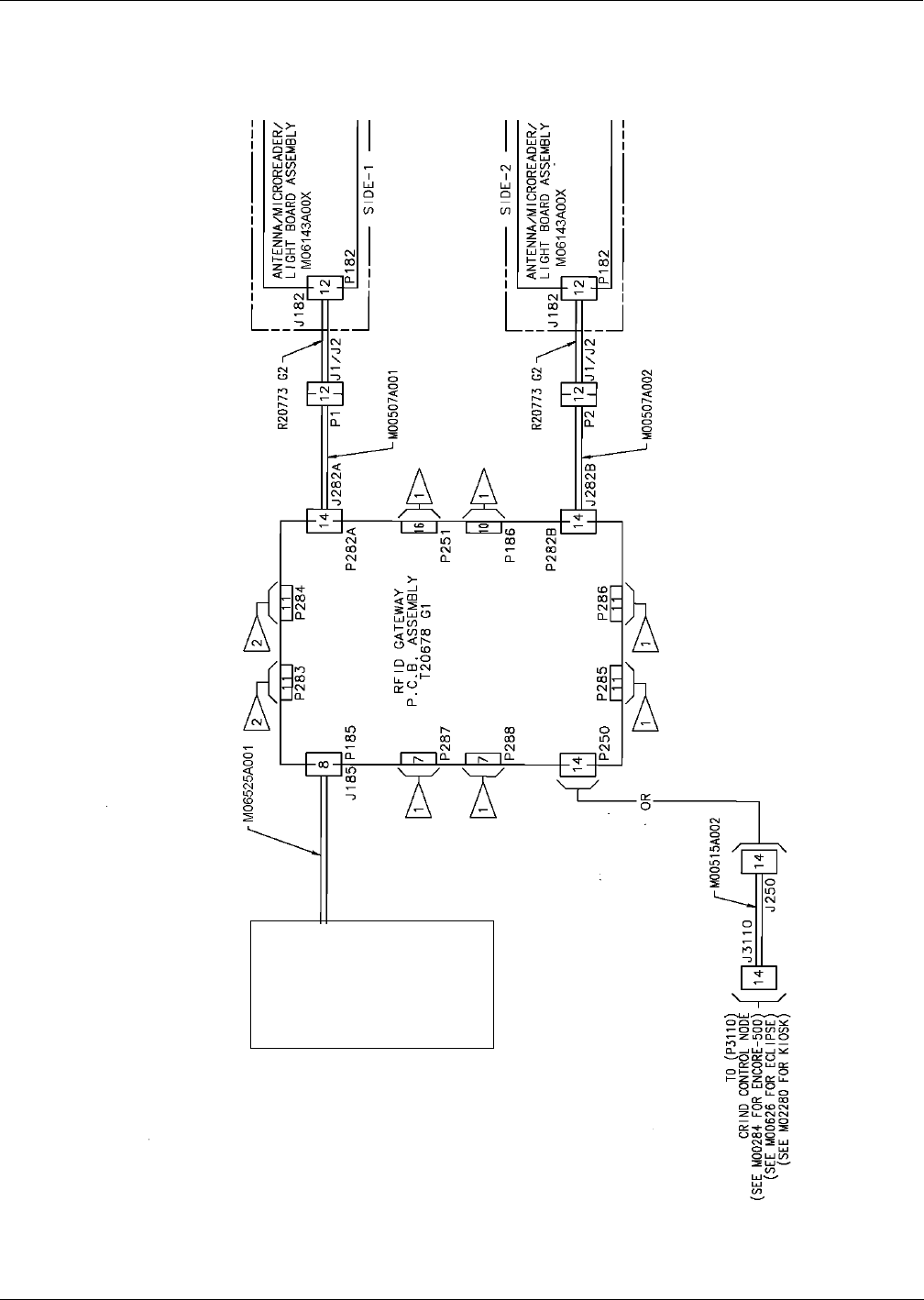
TRIND Cable Block Diagram R20775, Sheet 2
M04104AXXX
DIN Rail Power
Supply Assy.

Installation
Page 14 MDE-4544 Encore S Series TRIND Retrofit Kit C00011-011 Installation Manual • January 2006
Draft
Enabling the TRIND Device and Verifying Addresses
Perform the following steps to enable the TRIND device and verify the CRIND addresses that
with the Gateway Board.
1Restore power to the fueling units. Refer to MDE-3804 Encore and Eclipse Series Start-Up/
Service Manual.
2Initiate CRIND BIOS Diagnostics using Diagnostic Card Q12534-170.
3At the Diagnostic Startup Menu window select 1. Main Menu.
4At Main Menu window select 1. Device Config.
5At the Device Config window select 4. TRIND.
6At the TRIND Menu window for the Enable TRIND item, select 1. Yes to enable TRIND.
Press ENTER on the CRIND Keypad to have the selection accepted.
7Press the CANCEL key several times until the Diagnostic Startup Menu appears.
8At the Diagnostic Startup Menu window select 1. Main Menu.
9At the Main Menu window select 1. CRIND Config.
10 At the CRIND Config window select CRIND ID’s.
11 At the CRIND ID’s window select 1. CRIND ID Side A for side 1, or 2. CRIND ID Side B
for side 2.
12 At the CRIND ID Side A or CRIND ID Side B window, observe and make note of the
CRIND ID. Verify that the ID value is the same as the dispenser address setup on Gateway
Board T20678-GX.
MDE-4544 Encore S Series TRIND Retrofit Kit C00011-011 Installation Manual • January 2006 Page 15
Installation
Draft
Testing the TRIND Device
Perform the following steps to test the TRIND device. For details on wire connections, refer to
“TRIND Cable Block Diagram R20775, Sheet 2” on page 13.
1If the Site Controller is not operational, proceed to step 2. otherwise proceed to 6.
2If the Site Controller (G-SITE® or third party) is not operational (i.e., the application has not
been loaded), place the unit in the “stand alone” mode.
Note: The following steps are used to place the unit in the stand alone mode. Both the Stand
Alone jumper cable and the RFID Micro Reader PCA jump jack methods are listed. The
installer should select the method that is the most effective based on the type on
installation that is encountered.
3Locate the side 1 card cage cable harness and disconnect P1 of cable M00507A00X or locate
RFID Micro Reader PCA M06100A00X that’s part of the M06143A00X assembly, and place
a jumper in JP3. If using the jump jack in JP3 in the RFID Micro Reader PCA proceed to step
5, if not, go to step 4.
Note: The “jump jack” method is by far the most convenient way of placing the unit in the
standalone mode. It is recommended that this method be used if at all possible.
4Obtain Standalone Jumper Cable R20602-GX from the ASC TRIND Tool Kit, and connect the
P1/P2 end of the cable to the P1 end of M00507A00X cable for side 1. Refer to the “TRIND
Cable Block Diagram R20775, Sheet 2” on page 13 for the location of M00507A00X.
Note: Connect the jumper cable to side 1 only to ensure successful standalone operation.
Jumper cable connection places both side 1 and side 2 in standalone mode.
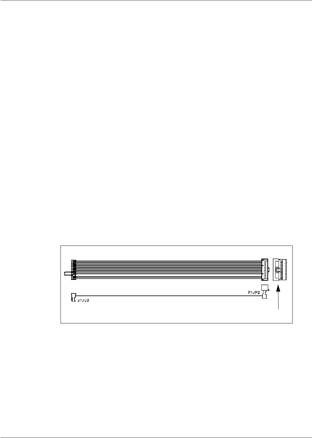
Figure 6: Standalone Jumper Cable R20602-GX
P1/P2
5Restore power to the card cage by reconnecting Power Cable M06525A001.
6Allow about 12 seconds for the Gateway Board software to start up, then verify that the SYNC
and STAT Light Emitting Diodes (LEDs) on RFID Micro Reader PCA M06100A00X flash,
and the OKT LED is illuminated.
Note: A visual of these indicators may be obtained by viewing TRIND from the front door
prior to the installation of the TRIND graphics.
Installation
© 2006 Gilbarco Inc.
7300 West Friendly Avenue • Post Office Box 22087
Greensboro, North Carolina 27420
Phone (336) 547-5000 • http://www.gilbarco.com • Printed in the U.S.A.
MDE-4544 Encore S Series TRIND Retrofit Kit C00011-011 Installation Manual • January 2006
Draft
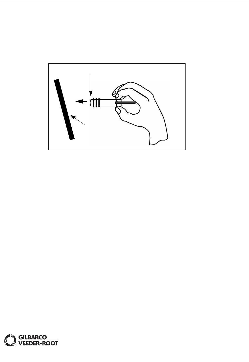
7From side 1 of the unit, point the hand held test tag (Q13630-02 from the ACS TRIND tool
kit) at the TRIND target graphic. The TRIND indicator will light when the tag is
approximately 3 inches or less away for the target graphic. Repeat for side 2.
Note: If the indicator fails to light, check whether the light on other side is on; if so, it
indicates a crossing of side 1 and 2 cables. Check connections.
Figure 7: TRIND Hand Held Test Tag
Target Graphic
POINT MUST BE WITHIN 3 INCHES OF TARGET GRAPHIC
IMPORTANT!
8Once testing has been successfully completed, remove power from the unit(s), remove the
jumper cable or jump jack from JP3, and restore power to the unit.
Completing Installation
After all testing has been completed, perform the following steps.
1Verify that all newly installed cables and wires are properly dressed and do not obstruct CIM
Door closure.
2Obtain FCC label nameplate M02962B007 from the kit, and install the label near the UL and
Gilbarco labels located on the inner column sheathing.
3Close and secure all doors.
4Install the TRIND graphics.
5Clean up the work site, removing all materials to be discarded and all tools.
CRIND®, Encore®, G-SITE® and TRIND® are registered trademarks of Gilbarco Inc.
Phillips® is a registered trademark of Phillips Screw Company.
UL® is a registered trademark of Underwriters’ Laboratories.