Gilbarco LFTRIND TRIND RFID Module User Manual XX XXXX Exhibit Cover
Gilbarco Inc. TRIND RFID Module XX XXXX Exhibit Cover
Gilbarco >
Manual

5015 B.U. Bowman Drive Buford, GA 30518 USA Voice: 770-831-8048 Fax: 770-831-8598
Certification Exhibit
FCC ID: N6SLFTRIND
IC: 827B-LFTRIND
FCC Rule Part: 15.209
IC Radio Standards Specification: RSS-210
ACS Report Number: 10-0134.W06.11.A
Manufacturer: Gilbarco Inc.
Model: LFTRIND
Manual
MDE-4909 FlexPay™ Unattended Payment Terminal (UPT) TRIND® Retrofit Kit Installation Manual · June 2010 Page 1
Preliminary
06/10/10
Introduction
Purpose
This manual provides instructions for installing the Transmitter/Receiver IN Dispenser
(TRIND®) Retrofit Kits in Encore® S Series units that contain the FlexPay™ Unattended
Payment Terminal (UPT).
The TRIND option allows the customer to automatically authorize the units equipped with
Card Reader IN Dispenser (CRIND®) device, using a low frequency hand-held Transponder
Tag provided by a Major Oil Company (MOC) or retailer.
This equipment has been tested and found to comply with the limits for a Class A digital
device pursuant to Part 15 of the Federal Communications Commission (FCC) Rules.
These limits are designed to provide reasonable protection against harmful interference
when the equipment is operated in a commercial environment. This equipment
generates, uses and can radiate radio frequency energy, and if not installed and used in
accordance with the instruction manual, may cause harmful interference to radio
communications. Operation of this equipment in a residential area may cause harmful
interference in that case the user must be required to correct the interference at his own
expense. Changes or modifications not expressly approved by the manufacturer could
void the user’s authority to operate this equipment.
The long term characteristics or the possible physiological effects of radio frequency
electromagnetic fields have not yet been investigated by Underwriters’ Laboratories,
Incorporated (UL®).
Industry Canada-specific Statements:
The term “IC:” before the radio certification number only signifies that Industry Canada
technical specifications were met.
This Class A digital apparatus meets all requirements of the Canadian Interference
Causing Equipment Regulations. Operation is subject to the following two conditions: (1)
this device may not cause harmful interference, and (2) this device must accept any
interference received, including interference that may cause undesired operation.
Cet appareillage numérique de la classe A répond à toutes les exigences de
l'interférence canadienne causant des règlements d'équipement. L'opération est sujette
aux deux suivantes: (1) ce dispositif peut ne pas causer l'interférence nocive, et (2) ce
dispositif doit accepter n'importe quelle interférence reçue, y compris l'interférence qui
peut causer l'opération peu désirée.
IMPORTANT INFORMATION
MDE-4909
FlexPay™ Unattended Payment Terminal (UPT)
TRIND® Retrofit Kit Installation Manual
June 2010

Page 2 MDE-4909 FlexPay™ Unattended Payment Terminal (UPT) TRIND® Retrofit Kit Installation Manual · June 2010
Introduction
Preliminary
Table of Contents
Topic Page
Introduction 1
Parts Lists 3
Important Safety Information 4
Installation 6
Required Reading
Before installing the equipment, the installer must read, understand, and follow:
• This Manual
• National Fire Protection Agency (NFPA) 30A, The Automotive and Marine Service
Station Code
• NFPA 70, The National Electric Code
• Applicable Federal, State, and Local Codes and Regulations
Failure to do so may adversely affect the safe use and operation of the equipment.
Note: This kit must be installed by a Gilbarco® Authorized Service Contractor (ASC).
Related Documents
Document
Number Title GOLD Library
MDE-3664 TRIND Start-Up, Service, and Parts Manual • CRIND and TRIND
• Service Manual
MDE-3804 Encore and Eclipse® Series Start-Up/Service Manual • Encore and Eclipse
• Service Manual
MDE-4516 Encore 500 S Series Owner’s Manual Encore and Eclipse
MDE-4903 FlexPay Startup and Service Manual FlexPay EPP and SCR
PT-1736 CRIND Card Reader Illustrated Parts Manual Parts Manual
PT-1936 Encore Series Pump and Dispenser Illustrated Parts Manual • Parts Manual
• Encore/Eclipse
• Encore and Eclipse Installers
Recommended Tools
To install TRIND Retrofit Kit M06879S00X, the following equipments are required:
• Metric Nut Drivers
• Standard Nut Drivers
• Needle Nose Pliers
• Pliers
• Pocket Knife
• Putty Knife or Scraper
• Diagnostic Card (Q12534-170)
• Metric Ratchet Set
• Standard Ratchet Set
• Flat-head Screwdriver
• Static Guard Wrist Strap
• TRIND Hand-held Test Tag (Transponder Tag)

MDE-4909 FlexPay™ Unattended Payment Terminal (UPT) TRIND® Retrofit Kit Installation Manual · June 2010 Page 3
Parts Lists
Preliminary
Abbreviations and Acronyms
Term Description
ASC Authorized Service Contractor
CRIND Card Reader IN Dispenser
FCC Federal Communications Commission
MOC Major Oil Company
NFPA National Fire Protection Agency
PCA Printed Circuit Assembly
TRIND Transmitter/Receiver IN Dispenser
UL Underwriters’ Laboratories
UPT Unattended Payment Terminal
Parts Lists
TRIND Retrofit Kit Parts List
The following table provides the parts list for the TRIND Retrofit Kit.
Description Part Number Quantity
Nut, Metric, Flange M00414B005 3
Cable, TRIND Power M06763A001 1
Decal, Patent and FCC M02962B013 1
Diagram, Block R20775 0
Diagram, Interconnection T20663 0
Assembly, Light and Inductor M06143A00X (see Note 1) 2
Lens, TRIND M05987B001 2
TRIND Graphic ENS0701G00X (see Note 2) 2
Card Reader Instructions Graphic ENS0702G010 2
Screw, Metric M4X8 M00419B117 8
Screw, Self-Tapping Hex Q11677-24 6
Cable, Light/Multi Protocol R20773-G2 2
Gasket, TRIND M06010B002 2
FlexPay UPT TRIND Retrofit Kit
Installation Manual
MDE-4909 1
Notes: 1) M06879S001 (for Mobil) contains Light and Inductor Assembly
(Red)- M06143A001. M06879S002 (for Exxon) contains Light and
Inductor Assembly (Amber)- M06143A002.
2) M06879S001 (for Mobil) contains TRIND Graphic (ENS0701G002).
M06879S002 (for Exxon) contains TRIND Graphic (ENS0701G001).
<<Please clarify, if these notes must be removed.>>
Page 4 MDE-4909 FlexPay™ Unattended Payment Terminal (UPT) TRIND® Retrofit Kit Installation Manual · June 2010
Important Safety Information
Preliminary
Important Safety Information
Note: Save this Important Safety Information section in a readily
accessible location.
This section introduces the hazards and safety precautions
associated with installing, inspecting, maintaining or servicing
this product. Before performing any task on this product, read
this safety information and the applicable sections in this
manual, where additional hazards and safety precautions for
your task will be found. Fire, explosion, electrical shock or
pressure release could occur and cause death or serious injury,
if these safe service procedures are not followed.
Preliminary Precautions
Y
ou are working in a potentially dangerous environment of
flammable fuels, vapors, and high voltage or pressures. Only
trained or authorized individuals knowledgeable in the related
procedures should install, inspect, maintain or service this
equipment.
Emergency Total Electrical Shut-Off
The first and most important information you must know is how
to stop all fuel flow to the pump/dispenser and island. Locate
the switch or circuit breakers that shut off all power to all fueling
equipment, dispensing devices, and Submerged Turbine
Pumps (STPs).
The EMERGENCY STOP, ALL STOP, and
PUMP STOP buttons at the cashier’s station
WILL NOT shut off electrical power to the
pump/dispenser. This means that even if you
activate these stops, fuel may continue to flow
uncontrolled.
You must use the TOTAL ELECTRICAL
SHUT-OFF in the case of an emergency and not
the console’s ALL STOP and PUMP STOP or
similar keys.
!
WARNING
!
Total Electrical Shut-Off Before Access
A
ny procedure that requires access to electrical components or
the electronics of the dispenser requires total electrical shut off
of that unit. Understand the function and location of this switch
or circuit breaker before inspecting, installing, maintaining, or
servicing Gilbarco equipment.
Evacuating, Barricading and Shutting Off
A
ny procedure that requires access to the pump/dispenser or
STPs requires the following actions:
• An evacuation of all unauthorized persons and vehicles
from the work area
• Use of safety tape, cones or barricades at the affected
unit(s)
• A total electrical shut-off of the affected unit(s)
Read the Manual
Read, understand and follow this manual and any other labels
or related materials supplied with this equipment. If you do not
understand a procedure, call a Gilbarco Authorized Service
Contractor or call the Gilbarco Support Center at
1-800-800-7498. It is imperative to your safety and the safety of
others to understand the procedures before beginning work.
Follow the Regulations
Applicable information is available in National Fire Protection
Association (NFPA) 30A; Code for Motor Fuel Dispensing
Facilities and Repair Garages, NFPA 70; National Electrical
Code (NEC), Occupational Safety and Hazard Association
(OSHA) regulations and federal, state, and local codes. All
these regulations must be followed. Failure to install, inspect,
maintain or service this equipment in accordance with these
codes, regulations and standards may lead to legal citations
with penalties or affect the safe use and operation of the
equipment.
Replacement Parts
Use only genuine Gilbarco replacement parts and retrofit kits on
your pump/dispenser. Using parts other than genuine Gilbarco
replacement parts could create a safety hazard and violate
local regulations.
Safety Symbols and Warning Words
This section provides important information about warning
symbols and boxes.
Alert Symbol
This safety alert symbol is used in this manual and on
warning labels to alert you to a precaution which must be
followed to prevent potential personal safety hazards. Obey
safety directives that follow this symbol to avoid possible injury
or death.
Signal Words
These signal words used in this manual and on warning labels
tell you the seriousness of particular safety hazards. The
precautions below must be followed to prevent death, injury or
damage to the equipment:
DANGER: Alerts you to a hazard or unsafe practice
which will result in death or serious injury.
WARNING: Alerts you to a hazard or unsafe practice
that could result in death or serious injury.
CAUTION with Alert symbol: Designates a hazard or
unsafe practice which may result in minor injury.
CAUTION without Alert symbol: Designates a hazard or
unsafe practice which may result in property or
equipment damage
Working With Fuels and Electrical Energy
Prevent Explosions and Fires
Fuels and their vapors will explode or burn, if ignited. Spilled or
leaking fuels cause vapors. Even filling customer tanks will
cause potentially dangerous vapors in the vicinity of the
dispenser or island.
DEF is non-flammable. Therefore, explosion and fire safety
warnings do not apply to DEF lines.
!
!
!
No Open Fire
Open flames from matches, lighters, welding torches
or other sources can ignite fuels and their vapors.
No Sparks - No Smoking
Sparks from starting vehicles, starting or using power tools,
burning cigarettes, cigars or pipes can also ignite fuels and
their vapors. Static electricity, including an electrostatic charge
on your body, can cause a spark sufficient to ignite fuel vapors.
Every time you get out of a vehicle, touch the metal of your
vehicle, to discharge any electrostatic charge before you
approach the dispenser island.
Working Alone
It is highly recommended that someone who is capable of
rendering first aid be present during servicing. Familiarize
yourself with Cardiopulmonary Resuscitation (CPR) methods, if
you work with or around high voltages. This information is
available from the American Red Cross. Always advise the
station personnel about where you will be working, and caution
them not to activate power while you are working on the
equipment. Use the OSHA Lockout/Tagout procedures. If you
are not familiar with this requirement, refer to this information in
the service manual and OSHA documentation.
Working With Electricity Safely
Ensure that you use safe and established practices in working
with electrical devices. Poorly wired devices may cause a fire,
explosion or electrical shock. Ensure that grounding
connections are properly made. Take care that sealing devices
and compounds are in place. Ensure that you do not pinch
wires when replacing covers. Follow OSHA Lockout/Tagout
requirements. Station employees and service contractors need
to understand and comply with this program completely to
ensure safety while the equipment is down.
Hazardous Materials
Some materials present inside electronic enclosures may
present a health hazard if not handled correctly. Ensure that
you clean hands after handling equipment. Do not place any
equipment in the mouth.
The pump/dispenser contains a chemical known to the
State of California to cause cancer.
WARNING
!
The pump/dispenser contains a chemical known to the
State of California to cause birth defects or other
reproductive harm.
WARNING
!
In an Emergency
Inform Emergency Personnel
Compile the following information and inform emergency
personnel:
• Location of accident (for example, address, front/back of
building, and so on)
• Nature of accident (for example, possible heart attack, run
over by car, burns, and so on)
• Age of victim (for example, baby, teenager, middle-age,
elderly)
• Whether or not victim has received first aid (for example,
stopped bleeding by pressure, and so on)
• Whether or not a victim has vomited (for example, if
swallowed or inhaled something, and so on)
Gasoline ingested may cause unconsciousness
and burns to internal organs.
Do not induce vomiting.
Keep airway open.
Oxygen may be needed at scene.
Seek medical advice immediately.
WARNING
!
Gasoline inhaled may cause unconsciousness
and burns to lips, mouth and lungs.
Keep airway open.
Seek medical advice immediately.
WARNING
!
Gasoline spilled in eyes may cause burns to eye
tissue.
Irrigate eyes with water for approximately
15 minutes.
Seek medical advice immediately.
WARNING
!
Gasoline spilled on skin may cause burns.
Wash area thoroughly with clear water.
Seek medical advice immediately.
WARNING
!
DEF is mildly corrosive. Avoid contact with eyes, skin, and
clothing. Ensure that eyewash stations and safety
showers are close to the work location. Seek medical
advice/recommended treatment if DEF spills into eyes.
WARNING
!
IMPORTANT: Oxygen may be needed at scene if gasoline has
been ingested or inhaled. Seek medical advice immediately.
Lockout/Tagout
Lockout/Tagout covers servicing and maintenance of machines
and equipment in which the unexpected energization or
start-up of the machine(s) or equipment or release of stored
energy could cause injury to employees or personnel.
Lockout/Tagout applies to all mechanical, hydraulic, chemical,
or other energy, but does not cover electrical hazards. Subpart
S of 29 CFR Part 1910 - Electrical Hazards, 29 CFR Part
1910.333 contains specific Lockout/Tagout provision for
electrical hazards.
MDE-4909 FlexPay™ Unattended Payment Terminal (UPT) TRIND® Retrofit Kit Installation Manual · June 2010 Page 5
Important Safety Information
Preliminary
Page 6 MDE-4909 FlexPay™ Unattended Payment Terminal (UPT) TRIND® Retrofit Kit Installation Manual · June 2010
Installation
Preliminary
Installation
To install TRIND Retrofit Kit, proceed as follows:
The installation procedures for this manual consists of the following sections:
•“Installing the Light and Inductor Assembly (M06143A00X)”
•“Installing the PIP Board” on page 8
•“Routing Cables” on page 9
•“TRIND Cable Block Diagram” on page 10
•“Enabling and Testing the TRIND Device” on page 11
•“Completing the Installation” on page 12
Installing the Light and Inductor Assembly (M06143A00X)
To install the Light and Inductor Assembly M06143A00X, proceed as follows:
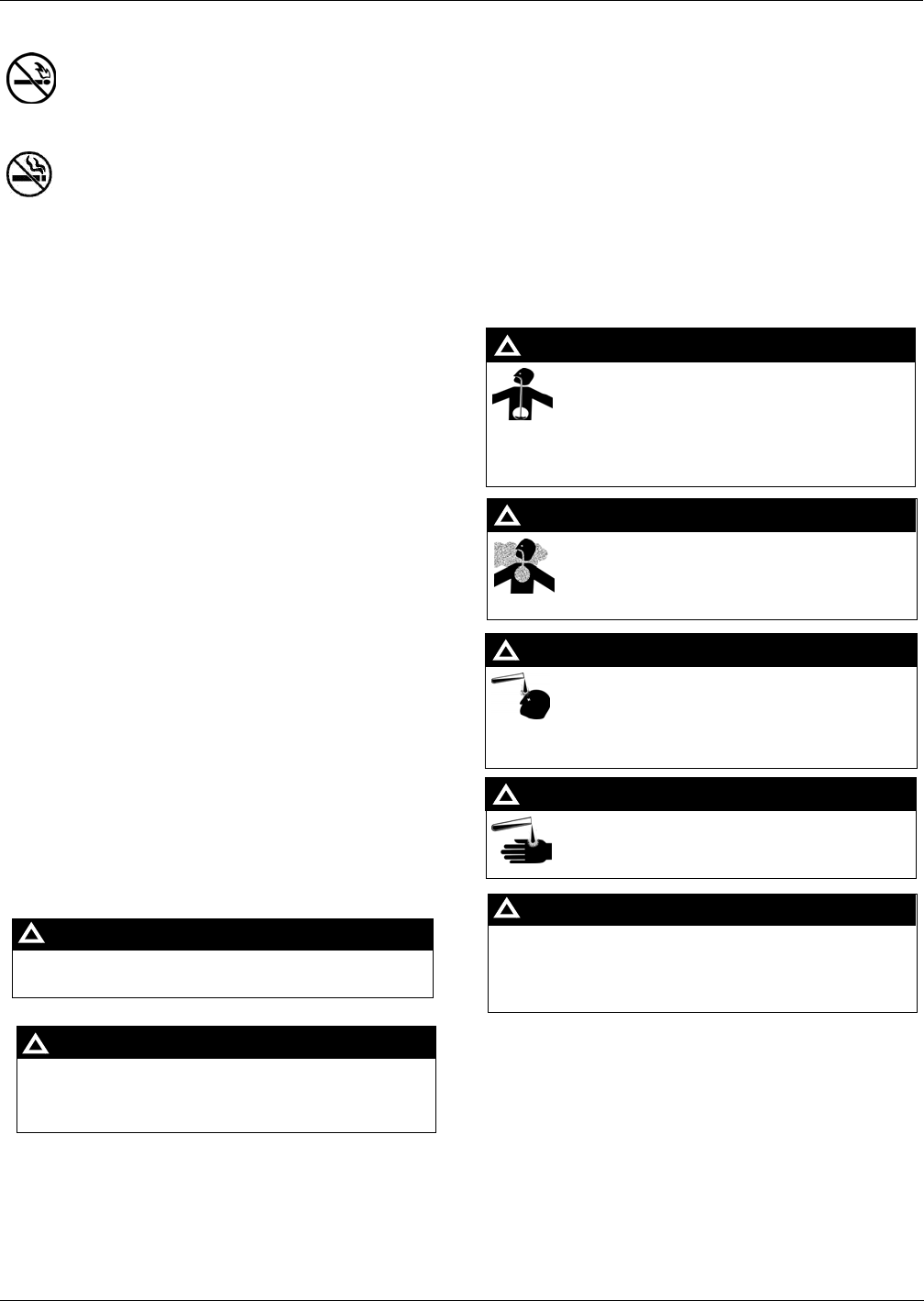
1Remove the small bracket securing the TRIND Blanking Panel, and knock out the TRIND
Blanking Panel (see Figure 1) using a hammer.
Figure 1: Encore S Door with TRIND Blanking Panel
Encore S Door with the Blanking Panel
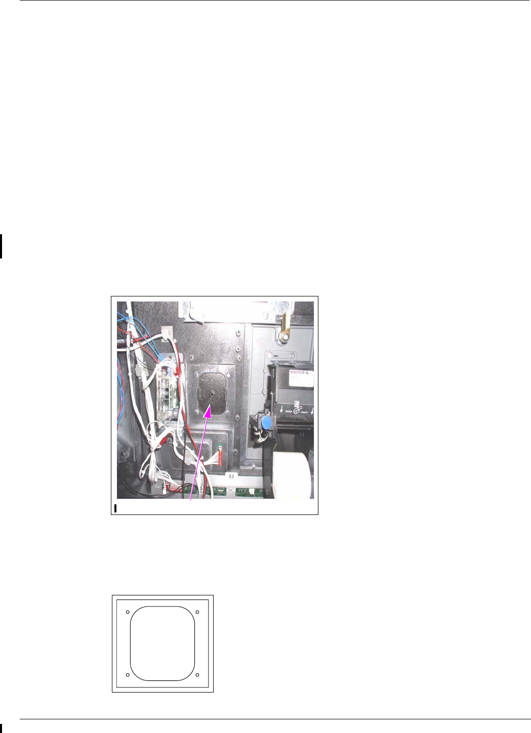
2Remove the narrow sealing gasket from the space that is now exposed outside the door and
place the TRIND lens gasket (M06010B002).
Figure 2: TRIND Lens Gasket
MDE-4909 FlexPay™ Unattended Payment Terminal (UPT) TRIND® Retrofit Kit Installation Manual · June 2010 Page 7
Installation
Preliminary
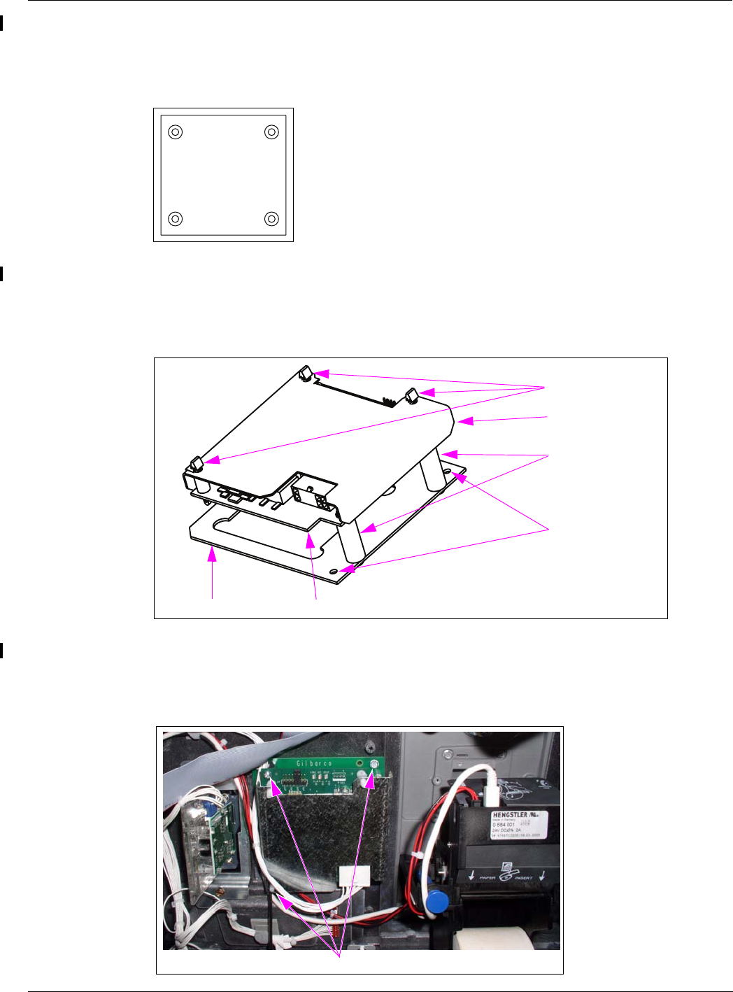
3Place the TRIND lens (M05987B001) on the TRIND gasket. Install and tighten the four
screws (M00419B117).
Figure 3: TRIND Lens
4Install the Light and Inductor Assembly (M06143A00X) inside the Encore S bezel using the
three screws (Q11677-24) provided with the kit, see Figure 5.
Figure 4: Light and Inductor Assembly (M06143A00X)
Circuit Board Support
Heat Shrink Tubing
TRIND PCB Shield
RFID Micro Reader PCA
RFID Antenna PCA
Holes for Screws
5Repeat steps 1 to 5 for the bezel on the other side.
Figure 5: Light and Inductor Assembly Secured to Door
Serrated Flange Screws (3)

Page 8 MDE-4909 FlexPay™ Unattended Payment Terminal (UPT) TRIND® Retrofit Kit Installation Manual · June 2010
Installation
Preliminary
Installing the PIP Board
To install the PIP Board, proceed as follows:
Depending on the system configuration, the unit may already have a PIP Board on one or both
sides. For TRIND function both sides must have a PIP Board.
1To remove BEEP Board (M09232A001) Printed Circuit Assembly (PCA), proceed as follows:
a Disconnect the M03695B004 USB Cable and M09267A001 Beep Cable.
b Remove the BEEP Board from the Peripheral Bracket.
Figure 6:
<<Please provide.>>
2Attach the PIP Board as shown in Figure 7.
Figure 7:
<<Please provide.>>
3Connect the M03695B004 USB Cable to P312 and M09267A001 Beep Cable to P214.
4Connect J311 from M07974A002 Cable to the system.
Figure 8:
<<Please provide.>>
MDE-4909 FlexPay™ Unattended Payment Terminal (UPT) TRIND® Retrofit Kit Installation Manual · June 2010 Page 9
Installation
Preliminary
Routing Cables
To install the Retrofit Kit Cables, proceed as follows:
Note: For more details on the connections, refer to “TRIND Cable Block Diagram” on
page 10.
<<Please provide the required updates.>>
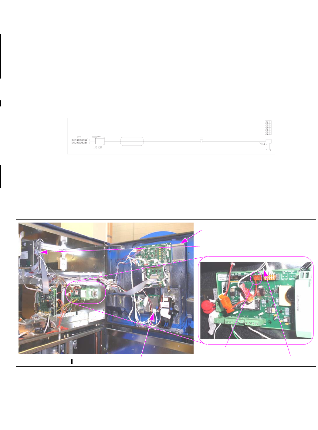
1Obtain the Light/Multi-Protocol Cable R20773-G4 from the kit and connect the J182 end of
the cable to P182 on the Light Board Assembly M06143A001.
Figure 9: Light/Multi-Protocol Cable (R20773-G4)
<<Please validate.>>
2Secure the R20773-G4 Cable to the door, and route and feed the other cables.
3For both main doors, use cable clamps to route cables to and along the door.
Figure 10: Door-To-Cabinet Cable Routing View
Door Node 4
Light/Multi-Protocol Cable (R20773-G4)
Ribbon Cable (M00507A001)
TRIND Power Cable (M06763A001)
P1300
<<Please validate.>>
4Connect the J204 end of the R20773-G4 Cable to P204 on the M09112A001 PIP Assembly.
Page 10 MDE-4909 FlexPay™ Unattended Payment Terminal (UPT) TRIND® Retrofit Kit Installation Manual · June 2010
Installation
Preliminary
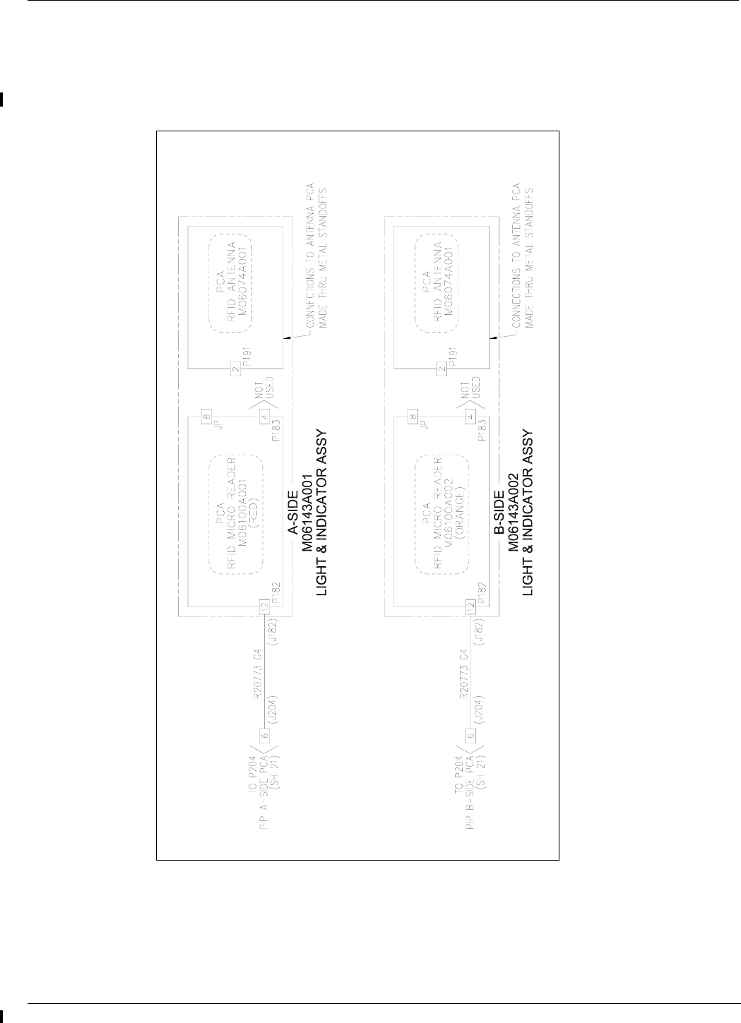
TRIND Cable Block Diagram
Figure 11: TRIND Cable Block Diagram
<<Please validate.>>
MDE-4909 FlexPay™ Unattended Payment Terminal (UPT) TRIND® Retrofit Kit Installation Manual · June 2010 Page 11
Installation
Preliminary
Enabling and Testing the TRIND Device
To enable the TRIND device proceed as follows:
1Restore power to the fueling units. Refer to MDE-3804 Encore and Eclipse Series
Start-Up/Service Manual.
2Initiate CRIND BIOS Diagnostics using the Diagnostic Card (Q12534-170).
3From the Diagnostic Startup Menu, select 1. Main Menu.
4From the Main Menu, select 2. Device Config.
5From Device Config, select 4. TRIND. The TRIND menu appears.
6To enable TRIND, select 1. Yes and select Enter on the CRIND Keypad.
7Select Cancel several times until the Diagnostic Startup Menu appears.
8Select 4. Test TRIND.
9Verify if the TRIND state is “Alive”.
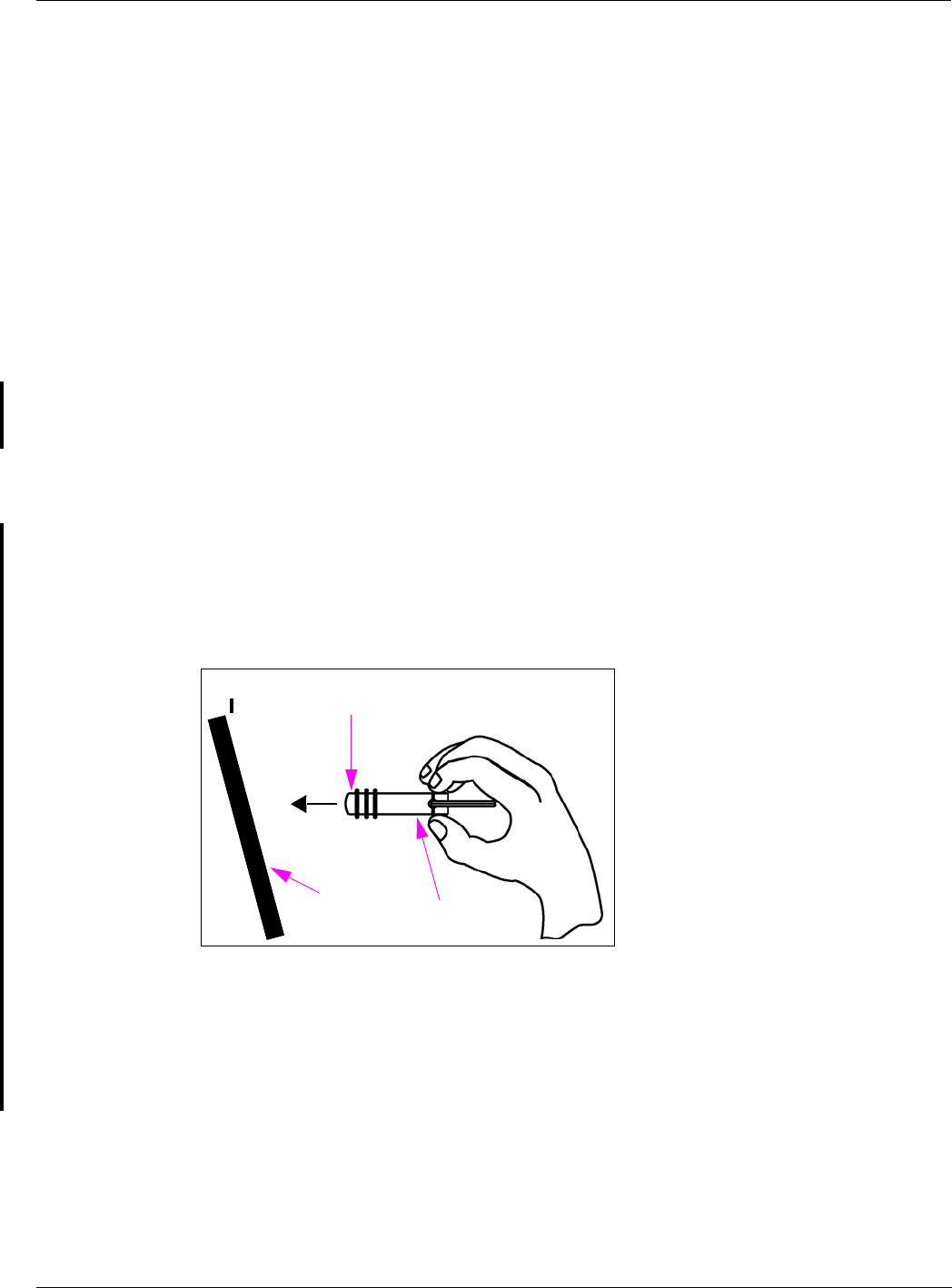
10 Hold a Transponder Tag in front of the reader.
Figure 12: TRIND Hand-held Test Tag
Target Graphic
POINT MUST BE WITHIN 3” OF TARGET GRAPHIC
IMPORTANT!
Transponder Tag
11 If the read is successful, the message “Good Read X” appears, where X is the number of good
reads.
Note: X must not start with 1. It is the number of good reads since the unit was first put into
service, or the last reset of the counter.
12 Select Cancel to exit the Test TRIND menu.
13 Select 2. Show Device Details.
Page 12 MDE-4909 FlexPay™ Unattended Payment Terminal (UPT) TRIND® Retrofit Kit Installation Manual · June 2010
Installation
Preliminary
14 Select 2. Reset Tags Read.
15 Select Cancel to exit the Show Device Details menu.
Note: The Show Device Details menu does not update the counts in real time. If the
Transponder Tag is read when the Show Device Details menu is displayed, then the
counter will not update until the screen is refreshed. To update the counter, exit the
Show Device Details menu and re-enter the menu.
Completing the Installation
After all the testing is completed, perform the following steps:
1Ensure that all newly installed cables and wires are properly dressed and do not obstruct main
door closure.
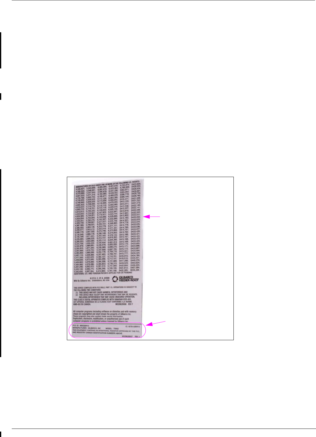
2Obtain the TRIND FCC label nameplate M02962B013 from the kit, and install the label under
the FCC/Patent label located on the inner column sheathing (see Figure 13).
Figure 13: Location of TRIND FCC Label Nameplate
<<Please provide the updated picture of M02962B013 FCC label.>>
TRIND FCC Label Nameplate
(M02962B013)
FCC/Patent Label
3Close and secure all the doors.
MDE-4909 FlexPay™ Unattended Payment Terminal (UPT) TRIND® Retrofit Kit Installation Manual · June 2010 Page 13
Installation
Preliminary
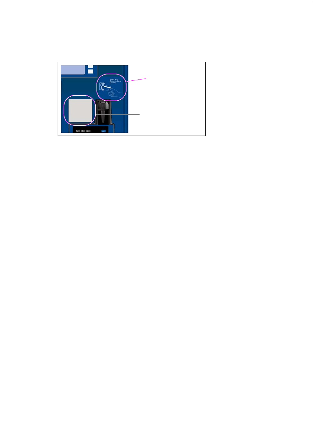
4Install the TRIND graphics on the TRIND lens and card reader instructions as shown in
Figure 14.
Figure 14: Location of TRIND Graphics and Card Reader Instructions
Card Reader Instructions
Location of TRIND Graphic
5Clean up the work site, removing all materials to be discarded and all tools.

© 2010 Gilbarco Inc.
7300 West Friendly Avenue · Post Office Box 22087
Greensboro, North Carolina 27420
Phone (336) 547-5000 · http://www.gilbarco.com · Printed in the U.S.A.
MDE-4909 FlexPay™ Unattended Payment Terminal (UPT) TRIND® Retrofit Kit Installation Manual · June 2010
CRIND®, Eclipse®, Encore®, Gilbarco®, and TRIND® are registered trademarks of Gilbarco Inc. FlexPay™ is a trademark of Gilbarco Inc.
UL® is a registered trademark of Underwriters’ Laboratories Inc.
Preliminary