Manual

MDE-4063 TRIND TIRIS Retrofit Kit C00011-010-XXXX Installation Manual• August 2001 Page 1
Preliminary
08-24-01
Introduction
Purpose
This manual provides instruction for installing Transmitter/Receiver In Dispenser (TRIND™)
Texas Instruments Registration and Identification (TIRIS™) Retrofit Kits C00011-010-XXXX
in The Advantage® Series and MPD®-3 Multi-Product Dispenser with InfoScreen®,
monochrome CRIND™ device, or single-line CRIND device.
The TRIND option allows customers to automatically authorize CRIND-equipped units, using
either a hand-held or auto-mounted transponder provided by a major oil company (MOC). Use
these kits for one- or two-sided units. Kits are customer specific, depending on unit type,
number of sides, and MOC.
Retrofit Kits C00011-010-XXXX are configured according to specific unit requirements.
Prerequisites
Before installing any TRIND kit, ensure that the existing CRIND device contains the
following.
•Z-180 logic board and software (T17764-XX), which is not configured in TRIND retrofit
kit. Refer to MDE-2628, Cash Acceptor Retrofit Assemblies for The Advantage Series.
•Plastic options doors for single-line/cash acceptor InfoScreen/cash acceptor and
monochrome/cash acceptor
Important Notice
This equipment has been tested and found to comply with the limits for a Class A digital
device pursuant to Part 15 of the FCC Rules. These limits are designed to provide reasonable
protection against harmful interference when the equipment is operated in a commercial
environment. This equipment generates, uses and can radiate radio frequency energy, and if
not installed and used in accordance with the instruction manual, may cause harmful
interference to radio communications. Operation of this equipment in a residential area is
likely to cause harmful interference in which case the user will be required to correct the
interference at his own expense. Changes or modifications not expressly approved by the
manufacturer could void the user’s authority to operate this equipment.
MDE-4063
TRIND™ TIRIS™
Retrofit Kits C00011-010-XXXX
Installation Manual
August 2001

Introduction
Page 2 MDE-4063 TRIND TIRIS Retrofit Kit C00011-010-XXXX Installation Manual• August 2001
Preliminary
08-24-01
Required Reading
Before installing the equipment, the installer must read, understand, and follow:
•this manual
•NFPA 30A, The Automotive and Marine Service Station Code
•NFPA 70, The National Electric Code
•applicable federal, state and local codes and regulations
•ASC TRIND Technology Update on page 20
Failure to do so may adversely effect the safe use and operation of the equipment.
Note: These kits must be installed by a Marconi ASC (Authorized Service Contractor)
Related Documents
Manual Description
MDE-2531 Pump and Dispenser Start-Up and Service Manual
MDE-2562 CRIND Service Manual
MDE-2628 Cash Acceptor Retrofit Assemblies for The Advantage Series
MDE-2620 Graphics Panel Application for The Advantage Series
MDE-3640 Authorized Service Contractor (ASC) TRIND Installation Tool Kit
MDE-3664 TRIND Start-Up and Service Manual
PT-1728 The Advantage Series Illustrated Parts Manual
PT-1736 CRIND Card Reader Illustrated Parts Manual
PT-1810 MPD Series Illustrated Parts Manual

MDE-4063 TRIND TIRIS Retrofit Kit C00011-010-XXXX Installation Manual• August 2001 Page 3
Introduction
Preliminary
08-24-01
Required Tools
The following equipment is needed to install TRIND™ kit C00011:
•Allen wrench set, American standard
•square (carpenter’s, 12'')
•clean cloth or rag
•center punch
•chip extraction tool, e.g., IC extraction, Digikey Part No. K158-ND or equivalent
•cutting oil
•deburring tool or rounded file
•drill motor, pneumatic (air)
•electric tape, black vinyl
•fish-tape, standard 1/8"
•hammer
•hacksaw
•hole saw, 7/8'' (for units with stop or call buttons on right option door)
•isopropyl alcohol (part number END-1082)
•knock-out punch set
•ladders, style ‘A’, quantity of two (2)
•multimeter
•pencil or marker
•pilot hole drill bits
•pliers
•pocket knife
•putty knife or scraper
•Q12534 CRIND diagnostic card
•ratchet set, standard
•screwdrivers, flat and Phillips head
•shears or snips, sheet metal
•static guard wrist strap
•TRIND ASC tool kit (refer to MDE-3640, ASC TRIND Installation Tool Kit K94577-01)

Parts Lists
Page 4 MDE-4063 TRIND TIRIS Retrofit Kit C00011-010-XXXX Installation Manual• August 2001
Preliminary
08-24-01
Parts Lists
C00011-XXXX Kit Configurations by Suffix
-Suffix Configured For See
-WF_S The Advantage Series 48" (wide frame) single-sided page 5
-WF_D The Advantage Series 48" (wide frame) double-sided
-NF_S The Advantage Series 36" (narrow frame) single-sided
-NF_D The Advantage Series 36" (narrow frame) double-sided
-MPDS MPD-3 single-sided with PMI bezel (slide-in faceplate) page 7
-MPDD MPD-3 double-sided with PMI bezel (slide-in faceplate)
-MPBS MPD-3 single-sided with Mack bezel (bolt-on faceplate) page 8
-MPBD MPD-3 double-sided with Mack bezel (bolt-on faceplate)

MDE-4063 TRIND TIRIS Retrofit Kit C00011-010-XXXX Installation Manual• August 2001 Page 5
Parts Lists
Preliminary
08-24-01
The Advantage Series Kit Parts
The Advantage Series Wide Frame (48’’) Kits
Kits C00011-WF_S (single-sided) and C00011-WF_D (double-sided) for The Advantage®
Series 48" units contain the following:
Description Part Number Quantity WF_S Quantity WF_D
1/4-20 bolt x 4” black K01914-70 4 8
1/4-20 nut, black Q11890-08 4 8
antenna assembly T20231-G1 1 2
bracket, antenna T20211-03 1 2
bracket, mounting T20211-02 1 0
bracket, positioning R20620-01 2 4
bracket, universal T20212-01 2 2
cable clamp, gray Q13558-04 10 10
cable group Q13863-06 (note 1) 1 1
card cage assembly T20606-G2 1 1
conduit, flexible black plastic Q13592-02 1 1
connector, tube fitting Q13591-01 1 2
cover, antenna top T20213-01 1 1
decal, UL N23951-06 1 1
door assembly T20613-G1 1 2
gasket, 1/2” x 1/16” strip Q11899-12 1.5 ft. 1.5 ft.
grommet, bulkhead seal Q13570-01 1 1
grommet, edge Q10315-06 1 ft. 1 ft.
grommet, heat shrinkable Q13570-01 1 1
grommet, round N15941-38 4 4
jump jack Q11011-01 9 9
label, UL certification N23957-G2 1 1
nameplate, FCC label N23949-09 1 1
screw, 10-32 black K85736 14 14
screw, sems, 6-32 x 3/8 Q12083-13 1 1
sealant, silicone END 1576 1 tube 1 tube
software, CRIND Bios TRIND K93744-XX (note 2) (note 2)
standoffs, circuit board (note 3) Q10651-16 4 4
tie-wrap Q10178-01 4 4
transmitter, dummy load R20526-G1 1
washer, flat N16599-48 1 1
Notes:
1. See “Cable Group Q13863-06” on page 6.
2. Order entry item.
3. For moving Gateway Board to top of card cage, see page “Relocate Gateway Board on Card Cage” on
page 24.

Parts Lists
Page 6 MDE-4063 TRIND TIRIS Retrofit Kit C00011-010-XXXX Installation Manual• August 2001
Preliminary
08-24-01
The Advantage Series Narrow Frame (36’’) Kits
Kits C00011-002-NF_S and C00011-002-NF_D kits for The Advantage Series 36" (narrow
frame) single-sided (NF_S) and double-sided (NF_D) units contain the following*:
Cable Group Q13863-06
Cable group Q13863-06 for all The Advantage Series units contains the following parts:
Description Part Number Quantity NF_S Quantity NF_D
antenna assembly T20231-G1 1 2
bracket, antenna T20211-03 1 2
cable clamp, gray Q13558-04 10 10
cable group Q13863-06 (note 1) 1 1
card cage assembly T20606-G2 1 1
cover, top T20215-01 1 1
decal, UL N23951-06 1 1
door assembly T20614-G1 1 2
grommet, edge Q10315-06 1 ft. 1 ft.
grommet, heat shrinkable Q13570-01 1 1
jump jack Q11011-01 9 9
label, UL certification N23957-G2 1 1
nameplate, FCC label N23949-09 1 1
screw, sems, 6-32 x 3/8 Q12083-13 1 1
sealant, silicone END 1576 1 tube 1 tube
software, CRIND Bios TRIND K93744-XX (note 2) (note 2)
standoffs, circuit board Q10651-16 4 4
tie wrap Q10178-01 4 4
transmitter, dummy load R20526-G1 1
washer, flat N16599-48 1 1
Notes:
1. See “Cable Group Q13863-06” on page 6.
2. Order entry item.
Description Part Number Quantity
cable, AC Power R20580-G1 1
cable, antenna (hi and low freq) M00878A002 1
cable, light/microreader R20773-G2 2
cable, TRIND to CRIND R20437-G01 1

MDE-4063 TRIND TIRIS Retrofit Kit C00011-010-XXXX Installation Manual• August 2001 Page 7
Parts Lists
Preliminary
08-24-01
MPD-3 Series Kit Parts
MPD-3 Units with PMI Bezels (Slide-in Faceplates)
C00011-002-MPDS Kits for single-sided units and C00011-002-MPDD Kits for double-sided
units with PMI bezels and slide-in faceplates contain the following*.:
Description Part Number Quantity MPDS Quantity MPDD
antenna assembly T20231-G1 1 2
bezel assembly T20616-G1 1 2
bracket, antenna T20211-03 1 2
cable assembly (J203/J806) R18163-G1 (notes 1 and 2) 1 1
cable clamp, gray Q13558-04 10 10
cable group (see note 2) Q13863-07 (note 2) 1 1
card cage assembly T20606-G2 1 1
cover, top T20214-01 1 1
decal, UL N23951-06 1 1
grommet, edge Q10315-06 1 ft. 1 ft.
jump jack Q11011-01 9 9
label, UL certification N23957-G2 1 1
manager keypad assembly T17549 1 1
nameplate, FCC label N23949-09 1 1
screw, sems, 6-32 x 3/8 Q12083-13 1 1
sealant, silicone END 1576 1 tube 1 tube
software, CRIND Bios TRIND K93744-XX (note 3) (note 3)
standoffs, circuit board Q10651-16 4 4
tie wrap Q10178-01 4 4
washer, flat N16599-48 1 1
Notes:
1. For Manager Keypad connection.
2. For detail refer to “Cable Group Q13863-07” on page 8.
3. Order entry item.

Parts Lists
Page 8 MDE-4063 TRIND TIRIS Retrofit Kit C00011-010-XXXX Installation Manual• August 2001
Preliminary
08-24-01
MPD-3 Units with Mack Bezels (Bolt-on Faceplates)
C00011-002-MPBS Kits for single-sided units and C00011-002-MPBD Kits for double-sided
units with Mack bezels and bolt-on faceplates contain the following*:
Cable Group Q13863-07
Cable Group Q13863-07 for all MPD-3 Series units contains the following parts:
Description Part Number Quantity MPBS Quantity MPBD
antenna assembly T20231-G1 1 2
antenna bracket kit T20211-03 1 2
bezel assembly T20616-G2 1 2
cable assembly (J203/J806) R18163-G1 (note 1) 1 1
cable clamp, gray Q13558-04 10 10
cable group Q13863-07 (note 1) 1 1
card cage assembly T20606-G2 1 1
decal, UL N23951-03 1 1
grommet, edge Q10315-06 1 ft. 1 ft.
jump jack Q11011-01 9 9
label, UL certification N23957-G1 1 1
manager keypad assembly T17549 1 1
nameplate, FCC label N23949-02 1 1
screw, sems, 6-32 x 3/8 Q12083-13 1 1
sealant, silicone END 1576 1 tube 1 tube
software, CRIND Bios TRIND K93744-XX (note 2) (note 2)
standoffs, circuit board Q10651-16 4 4
tie wrap Q10178-01 4 4
washer, flat N16599-48 1 1
Notes:
1. For detail refer to “Cable Group Q13863-07” on page 8.
2. Order entry item.
Description Part Number Quantity
cable, AC Power R20580-G1 1
cable, antenna (hi and low freq) M00878A002 1
cable, TRIND to CRIND R20437-G01 1

MDE-4063 TRIND TIRIS Retrofit Kit C00011-010-XXXX Installation Manual• August 2001 Page 9
Parts Lists
Preliminary
08-24-01
ASC TRIND™ Tool Kit K94577-01
Tool Description Part Number Quantity
co-axial cable tool Q13628-01 1
field strength sensor Q13626-01 1
test tag, TI/RFIDcar mount Q13630-01 1
test tag, TI/RFID hand held Q13630-02 1
threaded rod, 3/8-16 x 4" N23880-01 4
tuning tool, plastic tipped Q13631-01 1
Important Safety Information
Page 10 MDE-4063 TRIND TIRIS Retrofit Kit C00011-010-XXXX Installation Manual• August 2001
Preliminary
08-24-01
Important Safety Information
This section introduces the hazards and safety precautions associated with installing,
inspecting, maintaining or servicing this product. Before performing any task on this product,
read this safety information and the applicable sections in this manual, where additional
hazards and safety precautions for your task will be found. Fire, explosion, electrical shock or
pressure release could occur and cause death or serious injury if these safe service procedures
are not followed.
Preliminary Precautions
You are working in a potentially dangerous environment of flammable fuels, vapors, and high
voltage or pressures. Only trained or authorized individuals knowledgeable in the related
procedures should install, inspect, maintain or service this equipment.
The first and most important information you must know is how to stop all fuel flow to the
pump and island.
Emergency Total Electrical Shut-Off
Locate the switch or circuit breakers that shut-off all power to all fueling equipment,
dispensing devices, and submerged turbine pumps (STPs). These you must operate in the
event of an emergency.
Total Electrical Shut-Off Before Access
Any procedure requiring access to electrical components or the electronics of the dispenser
requires total electrical shut-off of that unit.
NFPA 30A, Section 4-1.2, published by the National Fire Protection Association, requires the
installation of an easily accessible switch or circuit breaker to shut-off the power to all fueling
equipment, dispensing devices and STPs in the event of an emergency. Know the function and
location of this switch or circuit breaker before inspecting, installing, maintaining, or servicing
Marconi equipment.
The EMERGENCY STOP, ALL STOP, and PUMP STOP buttons at the cashier’s
station WILL NOT shut off electrical power to the pump/dispenser.
This means that even if you activate these stops, fuel may continue to flow
uncontrolled.
You must use the TOTAL ELECTRICAL SHUT-OFF in the case of an
emergency and not only these cashier station “stops.”
WARNING
!
MDE-4063 TRIND TIRIS Retrofit Kit C00011-010-XXXX Installation Manual• August 2001 Page 11
Important Safety Information
Preliminary
08-24-01
Evacuation, Barricading and Shut-Off
Any procedures requiring accessing the pump/dispenser or STPs requires the following three
actions:
•An evacuation of all unauthorized persons and vehicles
•Using safety tape or cones as barricades to the effected units
•A total electrical shut-off of that unit
Read the Manual
Read, understand and follow this manual and any other labels or related materials supplied
with this equipment. If you do not understand a procedure, call a Marconi Authorized Service
Contractor or call the Marconi Call Center at 1-800-800-7498. It is imperative to your safety
and the safety of others to understand the procedures before beginning work.
Follow the Regulations
There is applicable information in: NFPA 30A: Automotive and Marine Service Code; NFPA
70: National Electrical Code (NEC); OSHA regulations; and federal, state, and local codes
which must be followed. Failure to install, inspect, maintain or service this equipment in
accordance with these codes, regulations and standards may lead to legal citations with
penalties or affect the safe use and operation of the equipment.
Safety Symbols and Warning Words
This section provides important information about warning symbols and boxes.
Alert Symbol
This safety alert symbol is used in this manual and on warning labels to alert you to
a precaution which must be followed to prevent potential personal safety hazards. Obey safety
directives that follow this symbol to avoid possible injury or death.
Important Safety Information
Page 12 MDE-4063 TRIND TIRIS Retrofit Kit C00011-010-XXXX Installation Manual• August 2001
Preliminary
08-24-01
Signal Words
These signal words used in this manual and on warning labels tell you the seriousness of
particular safety hazards. The precautions that follow must be followed to prevent death,
injury or damage to the equipment.
Prevent Explosions and Fires
Fuels and their vapors will become explosive if ignited. Spilled or leaking fuels cause vapors.
Even filling customer tanks will cause explosive vapors in the vicinity of dispenser or island.
No Open Flames
Open flames from matches, lighters, welding torches or other sources can ignite
fuels and their vapors.
No Sparks - No Smoking
Sparks from starting vehicles, starting or using power tools, burning cigarettes,
cigars or pipes can also ignite fuels and their vapors. Static electricity, including an
electrostatic charge on your body, can cause a spark sufficient to ignite fuels and their vapors.
After getting out of a vehicle, touch the metal of your vehicle to discharge any electrostatic
charge before you approach the dispenser island.
This signal word designates a hazard or unsafe practice which may result in minor injury.
This signal word is used to alert you to a hazard or unsafe practice which will result in
death or serious injury.
This alerts you to a hazard or unsafe practice that could result in death or serious injury.
CAUTION
When used by itself, CAUTION designates a hazard or unsafe practice which may result in
property or equipment damage.
CAUTION
DANGER
WARNING
!
!
!
MDE-4063 TRIND TIRIS Retrofit Kit C00011-010-XXXX Installation Manual• August 2001 Page 13
Important Safety Information
Preliminary
08-24-01
Prevent Electrical Shock and Sparks
Dispensing devices use high voltage. A potential shock hazard exists when working on or
around a dispensing device.
Follow OSHA lock-out and tag-out procedures.
Always turn OFF power to the dispensing device and associated submerged turbine pumps
(STPs) when servicing or making electrical wiring connections. Multiple disconnects may be
required.
Close Junction Boxes Tightly
Spilled or leaking fuels in the vicinity of electrical junction boxes can be hazardous if boxes
are not properly closed. Replace all bolts and tighten junction box cover before turning on AC
power. Do not use gaskets on junction box covers.
Field Wiring
Poorly wired pumps or dispensers could cause a fire, explosion or electrical shock. Place all
power and lighting wires in threaded, rigid metal conduits. Plug all unused junction box holes.
Never use knockout boxes or flexible conduit. Tighten all threaded connections and covers.
Do not use gaskets with junction box covers. Do not disturb sealing compound around wires at
junction box entrances. Use factory method of routing wires. Use tie wraps to keep unruly
wires away from pinch point and hinges. Tuck wires into enclosure before closing doors,
bezels, junction boxes, covers and breaker panels. Follow wiring recommendations in
installation or service manuals.
Proper Grounding is Required
Proper grounding is required for safe operation. See installation manual and applicable NEC,
NFPA and local electrical codes for requirements.
Avoid Pinched Wires
Pinched or cut wires (cables) may damage components. Exposed wires could create sparks and
electrical shorts when applying power.
The EMERGENCY STOP, ALL STOP, and PUMP STOP buttons at the
cashier’s station WILL NOT shut off electrical power to the pump/dispenser.
This means that even if you activate these stops, fuel may continue to flow
uncontrolled.
You must use the TOTAL ELECTRICAL SHUT-OFF in the case of an
emergency and not only these cashier station “stops.”
WARNING
!
Important Safety Information
Page 14 MDE-4063 TRIND TIRIS Retrofit Kit C00011-010-XXXX Installation Manual• August 2001
Preliminary
08-24-01
Hydraulic Pressure Releases and Fuel Leakage
Working on hydraulic systems can result in leakage of fuel that may also be under pressure.
Turn off all circuit breakers for unit being worked on, all dispensers using the same
grades of fuel, and all associated STPs.
Do not allow unauthorized or untrained individuals to service hydraulic equipment.
Shear valves, required by NFPA 30A, are intended to shut-off the flow of fuel at the dispenser
base (hydraulics area) during vehicle impact or fires. A single-poppet shear valve prevents fuel
from flowing from the underground tank. A double-poppet shear valve prevents fuel from
flowing from the underground tank and from the dispenser.
Protect Your Eyes
Spraying fuel from residual pressure in lines can cause serious eye injuries. Always
wear eye protection. Gasoline spilled in eyes may cause burns to eye tissue. Rinse eyes with
water for approximately 15 minutes. Seek medical advice immediately. It is not necessary to
wear eye protection unless performing hydraulic service.
React Quickly to Fuel Spills, Fires or Vehicle Impact
Follow these steps in the event of a fuel spill, fire, or vehicle impact.
1Use station EMERGENCY TOTAL ELECTRICAL SHUT-OFF immediately. Turn off all
system circuit breakers to the island.
2Call emergency numbers for fires, vehicle impact or any significant spills.
3Use safety tape, cones or barricades to block the work area. Do not go near fuel spill
or allow anyone else in the area.
The EMERGENCY STOP, ALL STOP, and PUMP STOP buttons at the cashier’s
station WILL NOT shut off electrical power to the pump/dispenser.
This means that even if you activate these stops, fuel may continue to flow
uncontrolled.
You must use the TOTAL ELECTRICAL SHUT-OFF in the case of an
emergency and not only these cashier station “stops.”
WARNING
!
MDE-4063 TRIND TIRIS Retrofit Kit C00011-010-XXXX Installation Manual• August 2001 Page 15
Important Safety Information
Preliminary
08-24-01
4Take precautions to avoid igniting fuel. Do not allow
starting of vehicles in the area and immediately stop use of open flames, smoking or power
tools in the area.
5Provide emergency and first aid assistance.
6Use approved and safe procedures to clean up all spills with a “fuel or gasoline absorbent”
material approved by your local regulatory agencies. (Dispose of fuel and hazardous absorbent
material promptly and according to the requirements of the fire department, local EPA, and
federal, state or local resources.)
If any gasoline has been inhaled, seek emergency help immediately.
Inhaled gasoline may cause unconsciousness and burns to lips, mouth and lungs.
WARNING
Gasoline spilled on skin may cause burns.
Wash area thoroughly with clean water.
Seek medical advice immediately.
WARNING
!
!
Important Safety Information
Page 16 MDE-4063 TRIND TIRIS Retrofit Kit C00011-010-XXXX Installation Manual• August 2001
Preliminary
08-24-01
Emergency and First Aid Information
Refer to phone book for emergency phone numbers. If needed, follow first aid instructions as
outlined in American Red Cross Standard First Aid manuals.
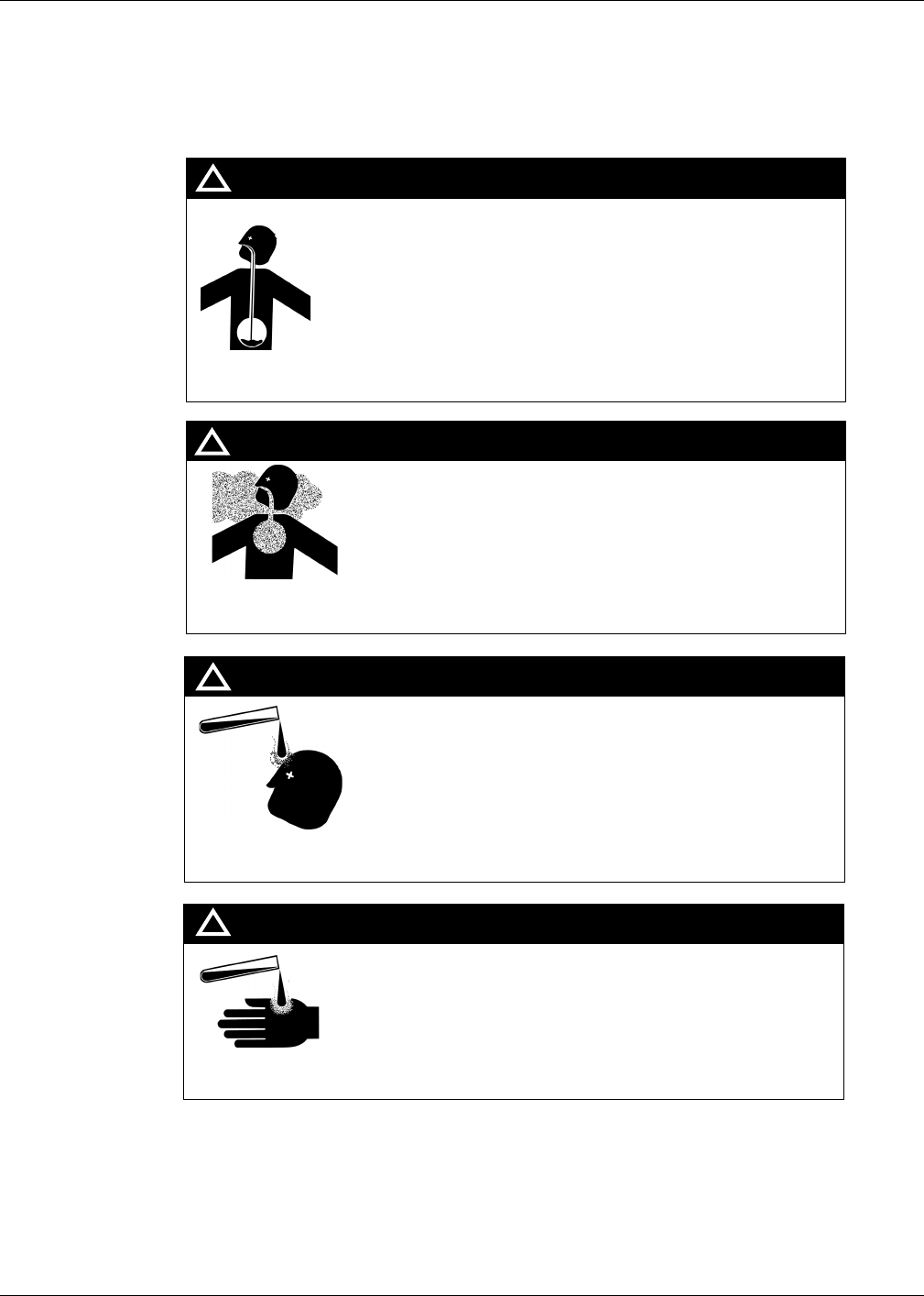
Gasoline
Ingestion
Gasoline Vapor
Inhalation
Gasoline spilled in eyes may cause burns to eye tissue.
Irrigate eyes with water for approximately 15 minutes.
Seek medical advice immediately
Gasoline spilled on skin may cause burns.
Wash area thoroughly with clear/water.
Seek medical advice immediately.
Gasoline On
Skin
Gasoline In
Eyes
Gasoline inhaled may cause unconsciousness and burns to lips,
mouth and lungs.
Keep airway open.
Seek medical advice immediately.
WARNING
WARNING
WARNING
WARNING
Gasoline ingested may cause unconsciousness and burns to
internal organs.
Do not induce vomiting.
Keep airway open.
Oxygen may be needed at scene.
Seek medical advice immediately.
!
!
!
!
MDE-4063 TRIND TIRIS Retrofit Kit C00011-010-XXXX Installation Manual• August 2001 Page 17
Important Safety Information
Preliminary
08-24-01
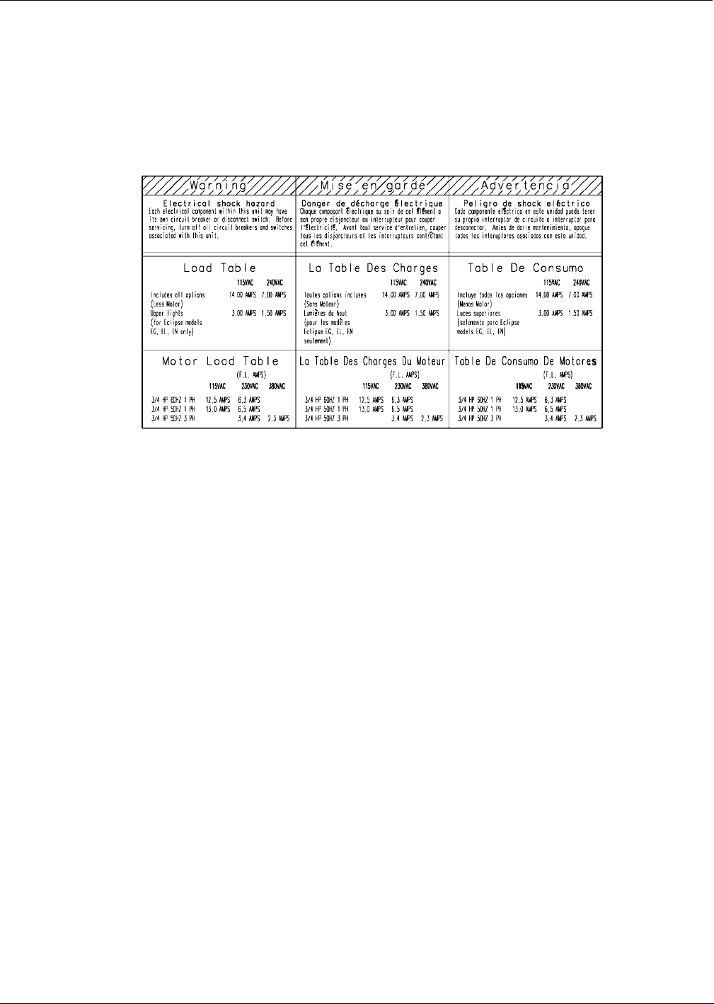
Warning Labels
Several types of warning labels appear on Marconi products to inform and remind users of
important safety information. Read, understand and follow these warnings.
Sample Warning Label
The following labels are typical of those you may find on Marconi’s products:
Working Alone
It is highly recommended that someone who is capable of rendering first aid be present during
servicing. Be familiar with Cardiopulmonary Resuscitation (CPR) methods if you are working
with or around high voltages. This information is available from the American Red Cross.
Always advise the station personnel about where you will be working, and caution them not to
activate power while you are working on the equipment. Use the OSHA tag out and lock out
procedures discussed later in this section.
Contacting Emergency Personnel
Keep the following emergency phone numbers at hand.
Ambulance:_____________________________________
Fire:___________________________________________
Police:_________________________________________
Poison Control Center:____________________________

Important Safety Information
Page 18 MDE-4063 TRIND TIRIS Retrofit Kit C00011-010-XXXX Installation Manual• August 2001
Preliminary
08-24-01
Informing Emergency Personnel
Compile the following information for emergency personnel:
•Location of accident (e.g. address, front/back of building, etc.)
•Nature of accident (e.g. possible heart attack, run over by car, burns, etc.)
•Age of victim (e.g. baby, teenager, middle-age, elderly)
•Whether or not victim has received first aid (e.g. stopped bleeding by pressure, etc.)
•Whether or not victim has vomited (e.g. if swallowed or inhaled something, etc.)
IMPORTANT: Oxygen may be needed at scene if gasoline has been ingested or inhaled. Seek
medical advice immediately.
Other Useful Safety Information
This subsection provides additional safety information.
OSHA Lock-Out and Tag-Out Requirements
OSHA Standard 29 CFR 1910-147 Control of Hazardous Energy Sources (Lock-Out/Tag-Out)
covers ways to avoid personal injury because power was turned on or fuel pressure was
applied unexpectedly while servicing equipment. The rule requires:
(1) Turning off equipment power and fuel under pressure.
(2) Use of a locking device (breaker, valve, etc.) or label device with a warning tag.
Station employees and service contractors need to understand and comply with this program
completely to ensure safety while the equipment is down.
Breakaways
Required by NFPA 30A, breakaways are emergency devices designed to retain liquid on both
sides of the breakaway point installed on each hose. Refer to manufacturer’s instructions for
proper installation.
Collection of Fuel in Approved Containers
NFPA 30A, Section 2, requires use of approved containers to collect, transport, and dispose of
fuel. Containers must be specifically designed and labeled for handling hazardous fuels.
Read Material Safety Data Sheets (MSDS)
Before working with any chemicals or fuels in and around a dispensing facility, read the
MSDS pertaining to those chemicals as prescribed in the Occupational Safety and Health
Administration Standard, 29 CFR 1910.1200. Refer to the supplier’s literature.
Replacement Parts
Use only genuine Marconi replacement parts and retrofit kits on your pump/dispenser. Using
parts other than genuine Marconi replacement parts could create a safety hazard and violate
local regulations.
MDE-4063 TRIND TIRIS Retrofit Kit C00011-010-XXXX Installation Manual• August 2001 Page 19
Important Safety Information
Preliminary
08-24-01
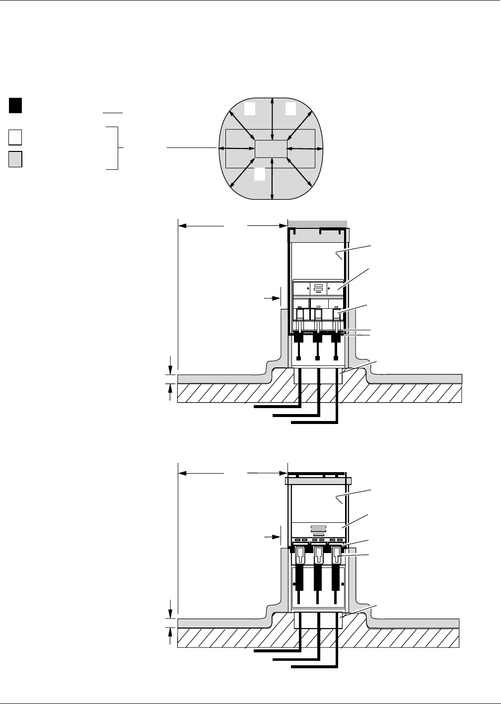
Classifying Hazardous Locations
Any activity that can cause an explosion (e.g., smoking, drilling, etc.) must be done well
outside the vapor area.
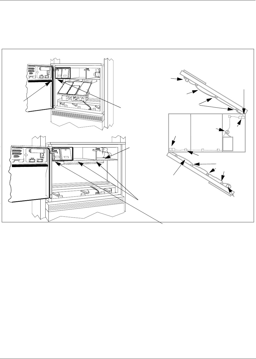
The following diagrams are based on NFPA 30A, section 6 and NFPA 70, section 514.
Fuel is present.
(Flammable Liquid)
Class 1 Division 2
(Hazardous Location)
Class 1 Division 1
(Hazardous Location)
Fuel Containing
Components
Vapor Areas
18"
18"
Unclassified location
area within electronics cabinet
above Air Gap.
Class 1 Division 1
within boot area.
Air Gap
20'
Pit box.
20'
20'
20'
Unclassified location
Electronics Head
Vapor Barrier
20'
Pit box.
18"
18"
Vertical Vapor Barrier
Vertical Vapor Barrier
Class 1 Division 1
within boot area.
MPD-3 Series
with
Vapor Barrier
The Advantage
Series with
Air Gap

ASC TRIND Technology Update
Page 20 MDE-4063 TRIND TIRIS Retrofit Kit C00011-010-XXXX Installation Manual• August 2001
Preliminary
08-24-01
ASC TRIND Technology Update
Note: AUTHORIZED SERVICE CONTRACTORS READ THIS SECTION BEFORE
PROCEEDING WITH INSTALLATION
The TRIND system utilizes technology and devices not commonly used in the industry. Read
the following carefully to familiarize yourself with relatively unique aspects of TRIND
systems and prevent field problems.
RF Transmission and Antennas
Located in the TRIND card cage is a transmitter printed circuit board (PCB). The RF antennas
are connected to this board during installation.
Applying power to the card cage with either antenna disconnected will result in damage to the
transmitter PCB.
•The transmitter PCB may be burned up immediately, or its effective life shortened
drastically.
•The PCB may perform properly at installation, but will require premature field service at a
later date.
For single-sided units, a ‘dummy load’ connector R20526-G1 is provided for unused ‘B’ side
of the PCB.
Note: Power must never be applied to the card cage without a load, either antennas or dummy
load connector.
Coaxial Cable
Coaxial antenna cables in cable harness M00878A002 used for TRIND systems are more
flexible and smaller diameter than more familiar coaxial cable, such as that used for cable
television. However, all coaxial cables share this feature:
Too severe a turn or bend in the cable will break the center (solid) wire.
This can result in a seemingly good but in actuality intermittent signal. It may also result in
what appears to be proper performance at installation that is followed by premature failure and
field service. Replacing damaged cable in the field is an extensive task.
In addition, a damaged cable will cause a situation where the transmitter PCB is powered
without load, and damage the PCB.
Note: Turns or bends in coaxial cables must be gradual loops, no sharper than a 1" radius (2"
diameter).
MDE-4063 TRIND TIRIS Retrofit Kit C00011-010-XXXX Installation Manual• August 2001 Page 21
Installation Instructions For The Advantage Series Units
Preliminary
08-24-01
Installation Instructions For The Advantage Series Units
Important Preinstallation Instruction.
Before beginning, read “Important Safety Information” on page 10 and “ASC TRIND
Technology Update” on page 20.
For MPD-3 Series, go to “Installation Instructions For MPD-3 Units” on page 38.
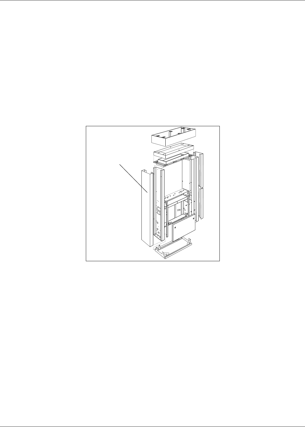
Removing Mobil Logo Display Cabinet
Use these procedures for dispensers with Mobil lighted logo display cabinets only. For units
without logo display cabinet (blue hat), proceed to ‘Preparing for Installation’ on page 22.
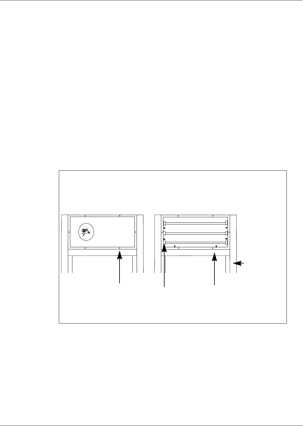
1Remove framed logo faceplates from both long sides of display cabinet by removing six
screws per side. See Figure 1. Save screws and logo faceplates for reassembly.
2Remove cover from electrical connection box in display cabinet and disconnect wires. Save
cover, screws and wire connectors for reassembly.
3Remove locking nut and washer from conduit nipple in display cabinet. Save nut and washer
for reassembly.
4Disconnect side cladding on both sides from light box by removing eight sets (four per side) of
bolts, flat washers, lock washers, neoprene washers and cage nuts. Dispose of removed
hardware.
Fastener assemblies
securing cladding to
display cabinet,
quantity of 8 each
With logo faceplate With logo faceplate removed
Bolts and washers
securing logo display
cabinet to top of unit,
quantity of 4 each
Side cladding
fastened to
outside sheathing
Faceplate screws,
total of 6
Figure 1:
Removing logo display cabinet
Installation Instructions For The Advantage Series Units
Page 22 MDE-4063 TRIND TIRIS Retrofit Kit C00011-010-XXXX Installation Manual• August 2001
Preliminary
08-24-01
5Remove four 3/8-16 bolts, lock washers, flat washers and soft aluminum flat washers securing
display cabinet to top of unit. Save all hardware except bolts for reassembly. Dispose of bolts.
6Carefully lift and remove display cabinet. Set cabinet aside for reassembly.
Note: Logo display cabinet weighs approximately seventy-five pounds. A crew of two, on
separate ‘A’ style ladders, are required to lift and remove cabinet.
Preparing For Installation
Perform these steps for all The Advantage® Series units
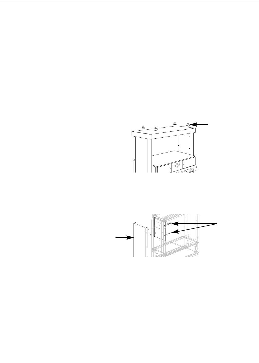
1Remove four hoisting brackets from top of unit by removing four bolts and washers. Dispose
of hoisting brackets. Save hardware for reassembly.
Note: On units with logo display cabinet, hoisting brackets have already been removed.
2From ‘A’ side of unit, remove inner sheathing on left column. Set sheathing and screws aside
for reassembly.
3Open main access doors. Refer to MDE-2531, Pump and Dispenser Start-Up/Service Manual
for access instructions.
Hoisting brackets
and 3/8” bolts
Figure 2:
Removing hoisting
brackets
Inside sheathing
and screws
‘A’ side
Figure 3:
Removing inner
sheathing
Outside sheathing
MDE-4063 TRIND TIRIS Retrofit Kit C00011-010-XXXX Installation Manual• August 2001 Page 23
Installation Instructions For The Advantage Series Units
Preliminary
08-24-01
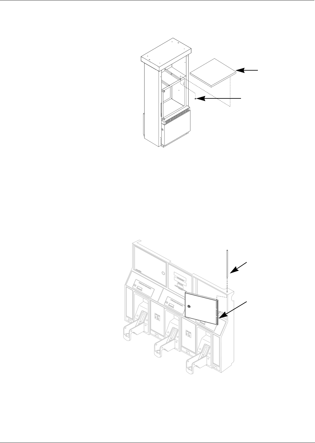
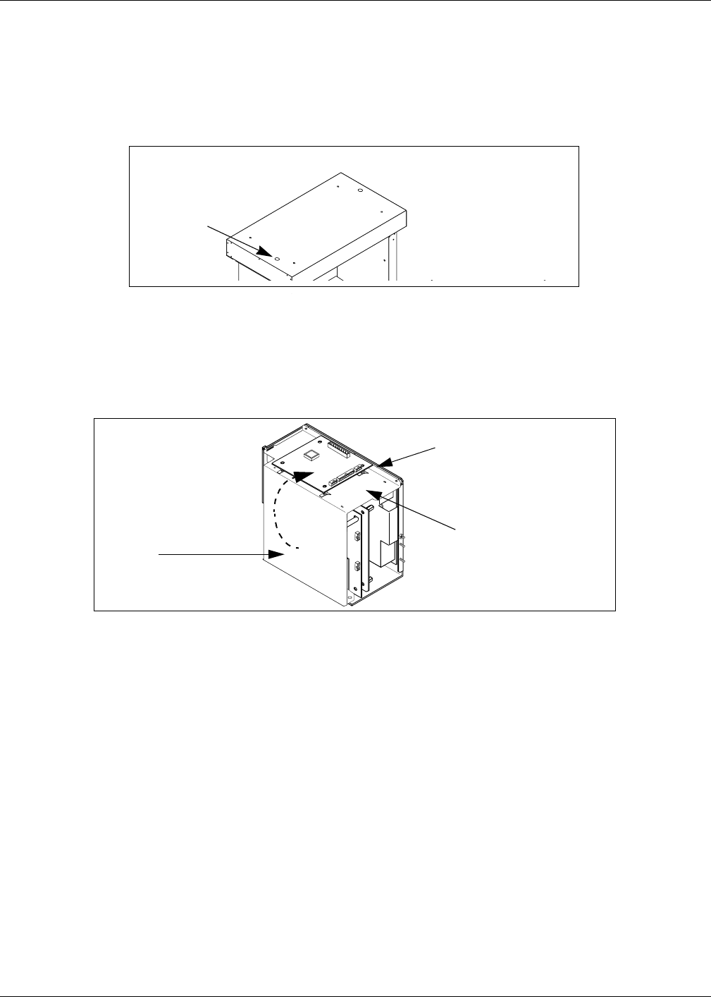
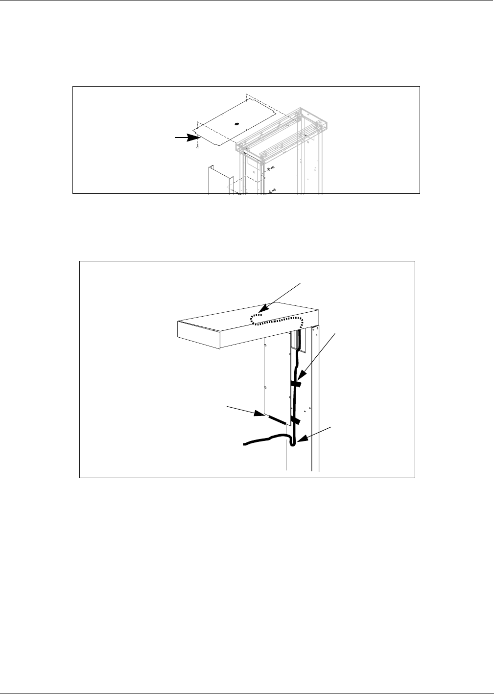
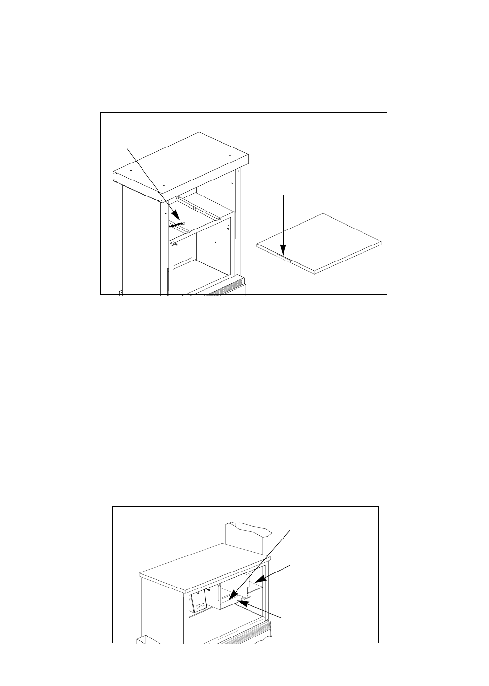
4Remove top cover from main panel by accessing mounting hardware from inside main
cabinet. See Figure 4. Save top cover and fastening hardware for reassembly.
5Remove any call or stop buttons, or magnetic switch hardware from door. Save all
removed hardware for reassembly.
6Remove door mounting pin and right options door. See Figure 5.
7Dispose of door. Save pin for reassembly.
Top cover
Access to top cover
fastening bolts from
inside main cabinet
Figure 4:
Removing cabinet
top cover
Door mounting pin
Right options door
Figure 5: Removing options door
Installation Instructions For The Advantage Series Units
Page 24 MDE-4063 TRIND TIRIS Retrofit Kit C00011-010-XXXX Installation Manual• August 2001
Preliminary
08-24-01
Removing Knockout in Unit Top Cover
1Remove knockouts from the near left side of unit top cover while facing each side of unit to
have antenna installed.
•For units without end plate, lift left side of top cover for access to knockout from bottom.
•For units with nine bolt end plates, remove plate for access.
2Lower top cover to original position.
Note: For units with end plate, do not replace plate at this time.
Relocate Gateway Board on Card Cage
Gateway board is shipped mounted to side of card cage. This accommodates immediate use
with the Encore™ Series dispensers. Relocate gateway board to top of card cage according to
the following steps:
1Remove Gateway board and standoffs from side of card cage.
Note: Existing standoffs do not need to be reused and should be removed.
2Secure gateway board to top of card cage as shown, using four Q10651-16 standoffs provided
with kit.
3Dispose of door. Save pin for reassembly.
Top cover knockout
Figure 6:
Unit Top Cover
Gateway Board location as
shipped
Gateway board reinstalled on top
P250 side of
board
Figure 7:
Gateway Board on
Card Cage
MDE-4063 TRIND TIRIS Retrofit Kit C00011-010-XXXX Installation Manual• August 2001 Page 25
Installation Instructions For The Advantage Series Units
Preliminary
08-24-01
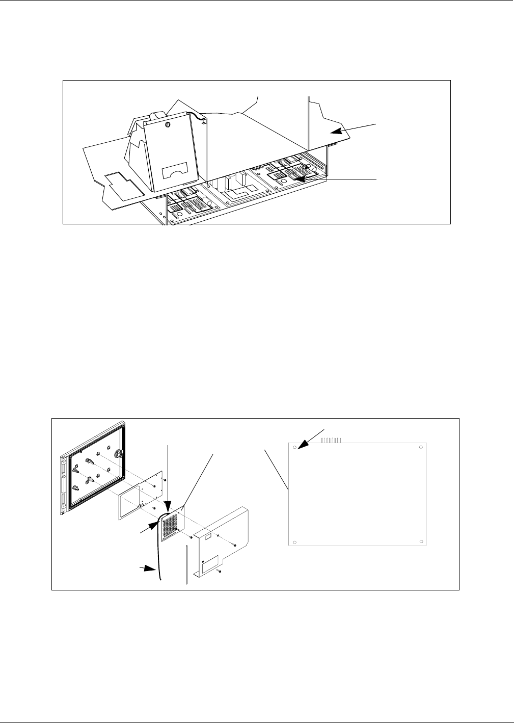
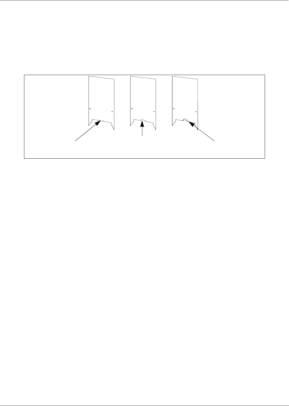
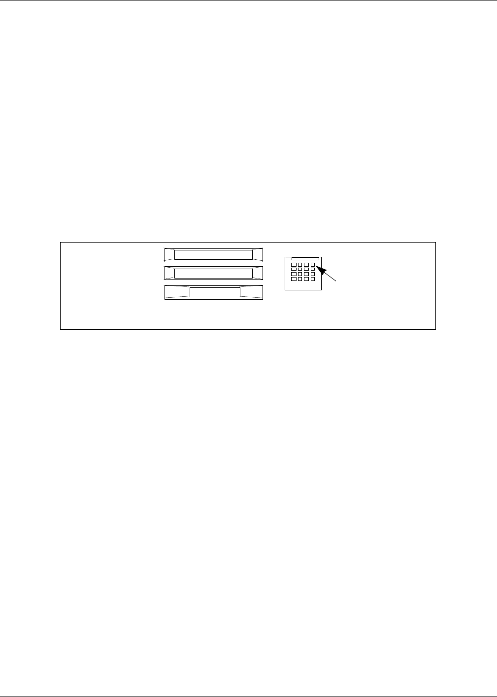
Modifying Right Options Door
For all units without stop or call button on right options door, go to ‘Re-installing Door Alarm
Switches’ on page 28, if unit has door alarm. If unit does not have door alarm, go to “Installing
Right Options Door” on page 28.
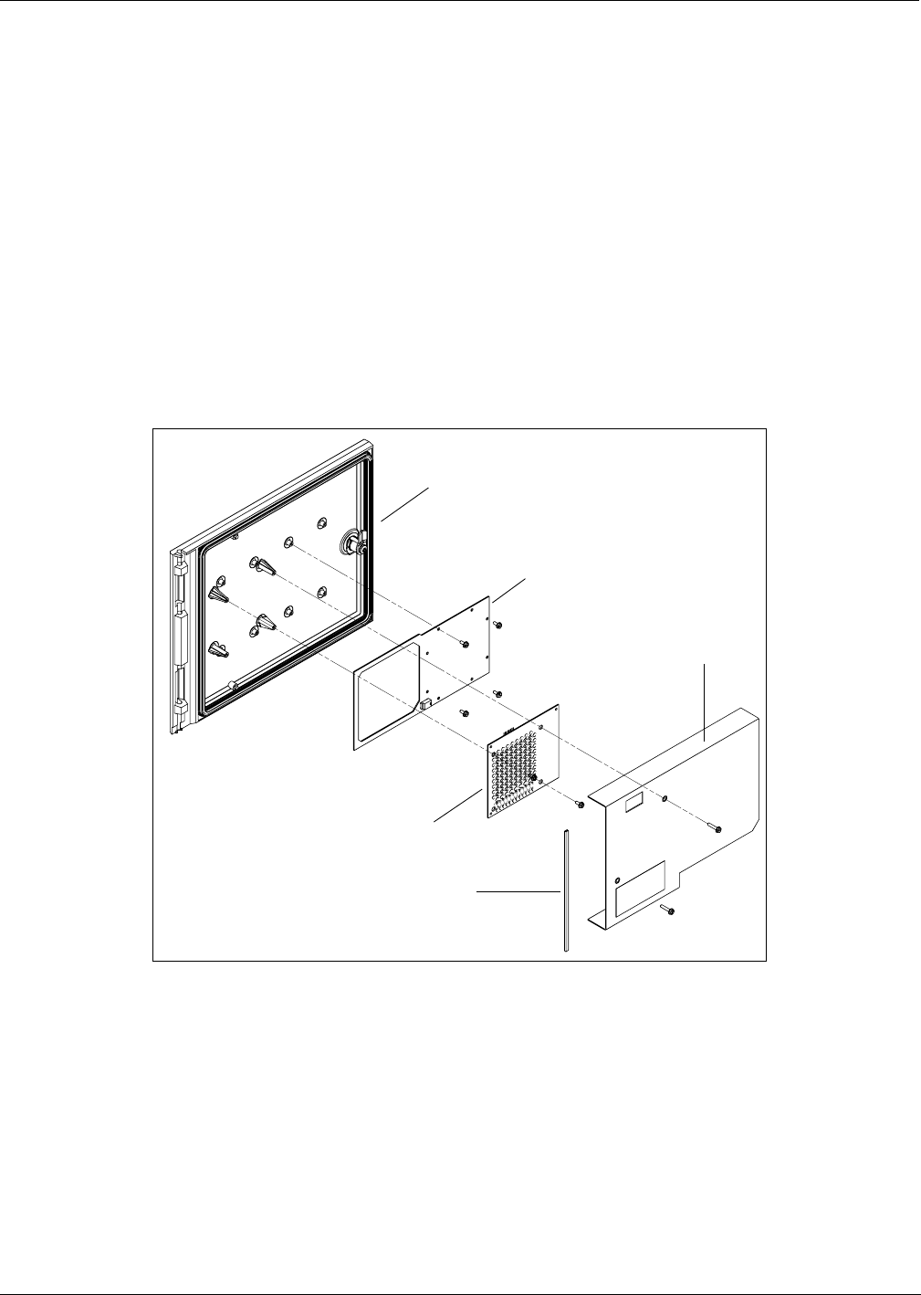
For 48" units with stop or call buttons previously installed, perform the
following steps.
Remove all hardware from new right options door according to the following steps and save
all parts for reassembly.
•Remove two screws mounting door shield on rear of door.
•Disconnect cable R20522-G2 from light/microreader printed circuit board (PCB) by
disconnecting J181 on cable from P181 on board.
•Remove Light/Microreader PCB.
•Remove screws and antenna board.
Door
shield
Antenna PCB
T20524
Light/Microreader
PCB T20601
Strip grommet
Clear door assembly
Installation Instructions For The Advantage Series Units
Page 26 MDE-4063 TRIND TIRIS Retrofit Kit C00011-010-XXXX Installation Manual• August 2001
Preliminary
08-24-01
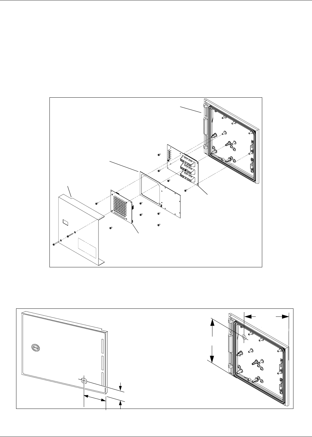
For 36" units with stop or call buttons previously installed, perform the
following steps.
Remove all hardware from new right options door according to the following steps and save
all parts for reassembly.
•Remove two screws mounting door shield on rear of door.
•Disconnect cable R20522-G2 from light/microreader printed circuit board (PCB) by
disconnecting J181 on cable from P181 on board.
•Remove Light/Microreader PCB.
•Remove screws and antenna board.
•Remove display PCB
For all units, do the following:
1Mark placement of pump stop or call button on new right options door by measuring from
door edges as shown.
2Away from fuel island, drill a 7/8 inch diameter hole in the location shown above. Remove any
burrs around hole with deburring tool or rounded file.
Door
shield
Antenna PCB
T20524
Light/Microreader
PCB T20601
Clear door assembly
Display PCB
1 9/16"
3 3/16"
Hole location for pump stop or call button 10 1/64"
8 13/16"
Wide Frame
Door measured
from front
Narrow Frame
Door measured
from rear
MDE-4063 TRIND TIRIS Retrofit Kit C00011-010-XXXX Installation Manual• August 2001 Page 27
Installation Instructions For The Advantage Series Units
Preliminary
08-24-01
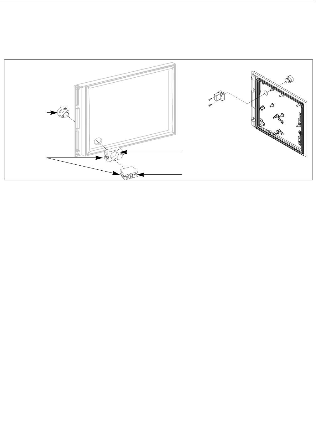
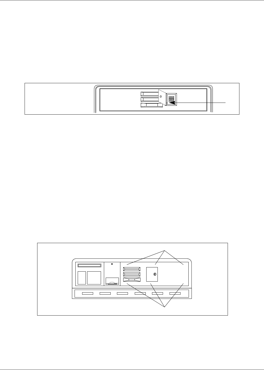
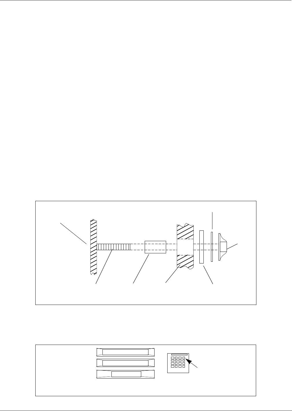
Reinstalling Button
1Hold contact base on back of door and align with hole drilled earlier.
2Insert push button from front of door by aligning tabs with slots in base.
3Turn push button 45° clockwise to lock button to base.
4Tighten two screws on base to secure push button and base assembly to door.
Note: Do not overtighten screws.
5Attach contact block to base with center screw if not already installed.
6Reinstall all new right options door hardware by reversing procedures in Step 1 of “Modifying
Right Options Door” on page 25.
Contact Block
Push button
BaseContact switch
base assembly
Re-installing
button(s)
Wide Frame Door
Narrow Frame
Door
Installation Instructions For The Advantage Series Units
Page 28 MDE-4063 TRIND TIRIS Retrofit Kit C00011-010-XXXX Installation Manual• August 2001
Preliminary
08-24-01
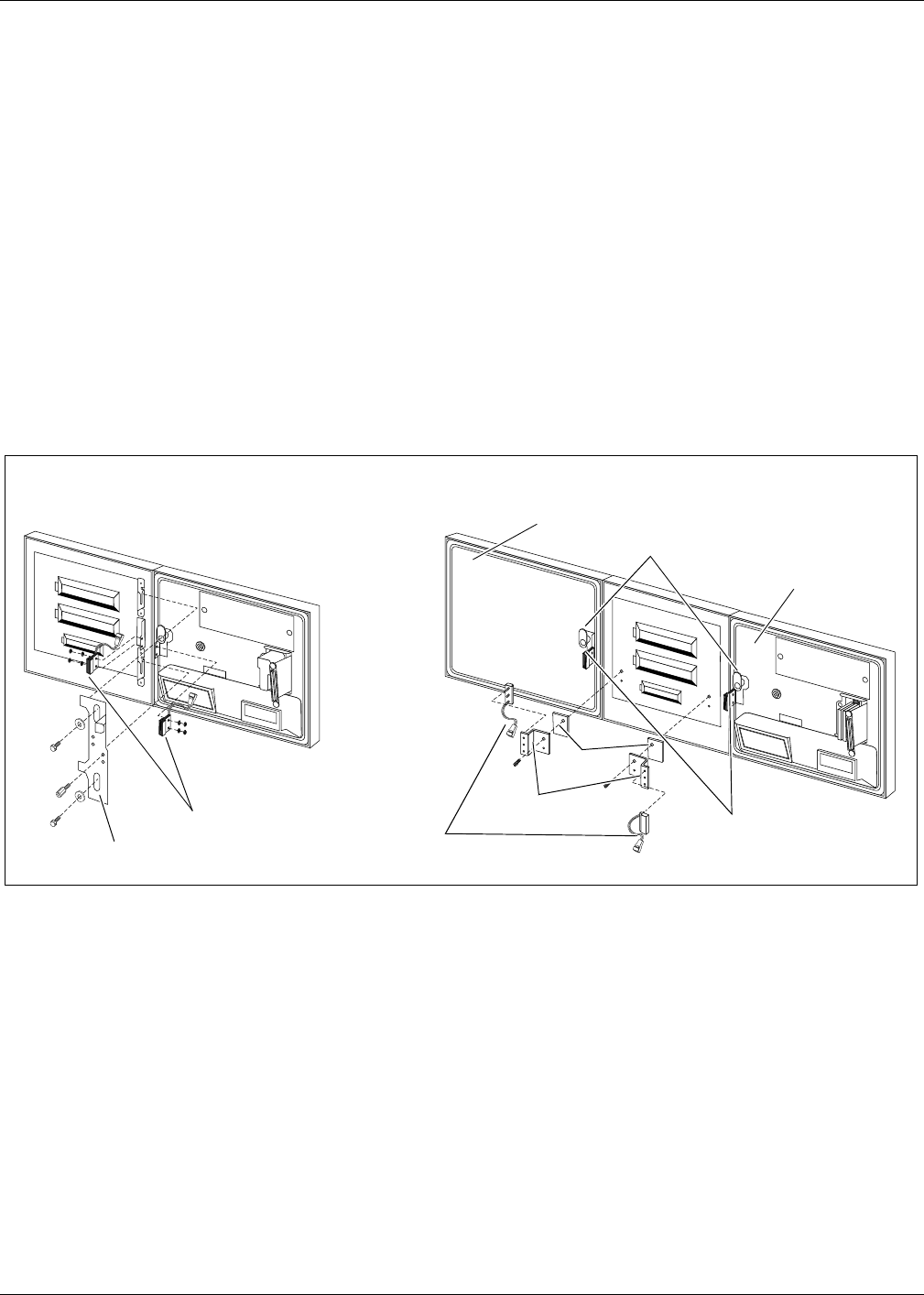
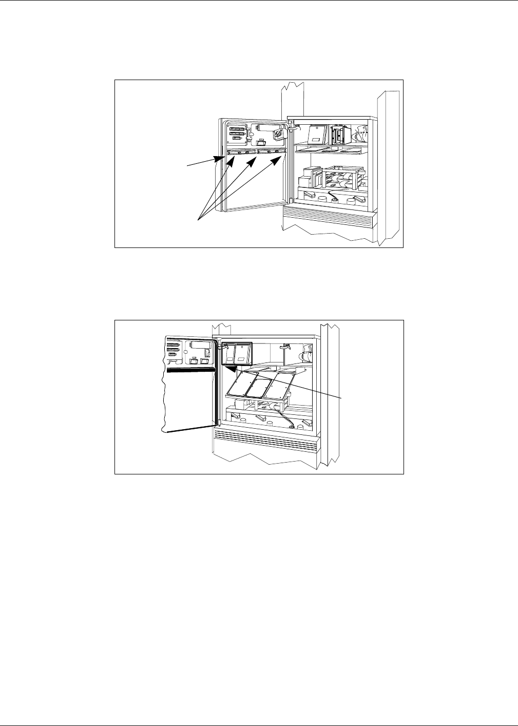
Reinstalling Door Alarm Switches
For units with cash acceptors, follow these steps to reinstall door alarm assemblies on TRIND
right option doors. Refer to diagram on this page for more information. Perform each step for
both ‘A’ and ‘B’ side right option doors. If unit does not have door alarm, go to ‘Installing
Right Option Door’ on page 28.
1Reinstall C-clips removed from old right side option doors.
2Install door alarm assembly to door alarm assembly bracket with screw previously removed.
3Attach door alarm assembly bracket to display board with screw previously removed.
Note: Replace the piece of fiberboard between door alarm bracket assembly and display
board.
4Be sure magnet does not touch door alarm door bracket. Slightly move door alarm door
bracket away, if necessary.
5Reinstall all new right options door TRIND hardware by reversing procedures in Step 1 of
“Modifying Right Options Door” on page 25.
Installing Right Options Door
Install new TRIND/TIRIS right options door (one per side for two-sided units), using pin(s)
removed and saved in Step 7 on page 23.
Left option door
Right option door
Door alarm assembly
Fiber
board
Door alarm
assembly bracket
C-clip
Door alarm door bracket
Door alarm assembly
Door alarm
assembly bracket
Back View of 36" Unit
Option Doors Back View of 48" Unit
Option Doors
MDE-4063 TRIND TIRIS Retrofit Kit C00011-010-XXXX Installation Manual• August 2001 Page 29
Installation Instructions For The Advantage Series Units
Preliminary
08-24-01
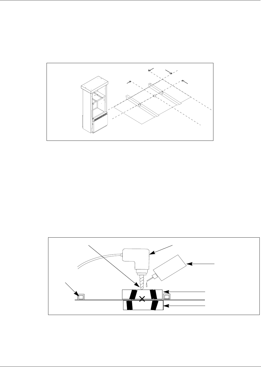
Installing Bulkhead Grommet
1Disconnect two cables and remove ground connector to ‘A’ side printer. Remove printer from
unit and save for reinstallation.
2While facing ‘A’ side of unit, measure 6" in toward center of cabinet top from outside edge of
top, and draw a line on top cover.
3Measure 10.5" in from left side of top, and draw a line. Intersection of both lines is pilot hole
location.
4In packaging materials, locate thick rubber packing that can be broken into flat sided pieces,
approximately six inches round, square or random.
5On one flat side of thick rubber piece, apply light coating of cutting oil.
6With oil coated surfaces in contact with metal surfaces, heavily tape one each foam piece to
top and bottom of main cabinet top, above and below drilling point marked.
Note: For foam piece taped to top, mark foam with marking pen or pencil to identify drilling
point under foam. Drilling point location accuracy of plus or minus 1/2" is acceptable.
.
7Cover shelf area under drilling position with plastic. Kit packaging materials may be used.
6"
10.5"
'B' Side
'A' Side
Locating
bulkhead
grommet hole
Cutting oil
Foam pieces taped to
cabinet above
and below drilling point
Pneumatic (air) drill
Gusset
on
cabinet
top, seen
from side
Drilling point marked

Installation Instructions For The Advantage Series Units
Page 30 MDE-4063 TRIND TIRIS Retrofit Kit C00011-010-XXXX Installation Manual• August 2001
Preliminary
08-24-01
8Follow these mandatory safety guidelines:
•Do not use electric drill. Use only pneumatic (air) drill set or controlled for low speed only
(300-500 rpm) or hand operated drill.
•Deposit a few drops of cutting oil at drilling point and on drill bit, to keep bit from
binding, to quench sparks and to bind drill shavings.
9Drill through foam pieces, going only as deep as required to penetrate top cover, beginning
with small diameter bit (approximately 1/8") and gradually increasing bit size until adequate
pilot hole is made.
Note: Hole 3/8" in diameter should be sufficient as pilot for knockout.
10 Remove both top and bottom foam pieces, being careful that all drilling residue and oil is
removed from cabinet area. Wipe off cabinet surface, top and bottom, with clean cloth or rag.
Note: Use file or deburring tool to remove burrs or edges that may cut hands.
11 Using hydraulic or manual knockout punch, make one inch (1") diameter hole.
12 Remove plastic covering hardware by folding inwards to retain any drilling residue, and
dispose of plastic.
13 Carefully check interior of main cabinet for trash or residue and clean as needed.
14 Position bulkhead seal grommet (Q13570-01) with O-ring beneath hole.
15 Secure grommet in place with locking nut from top of cabinet.
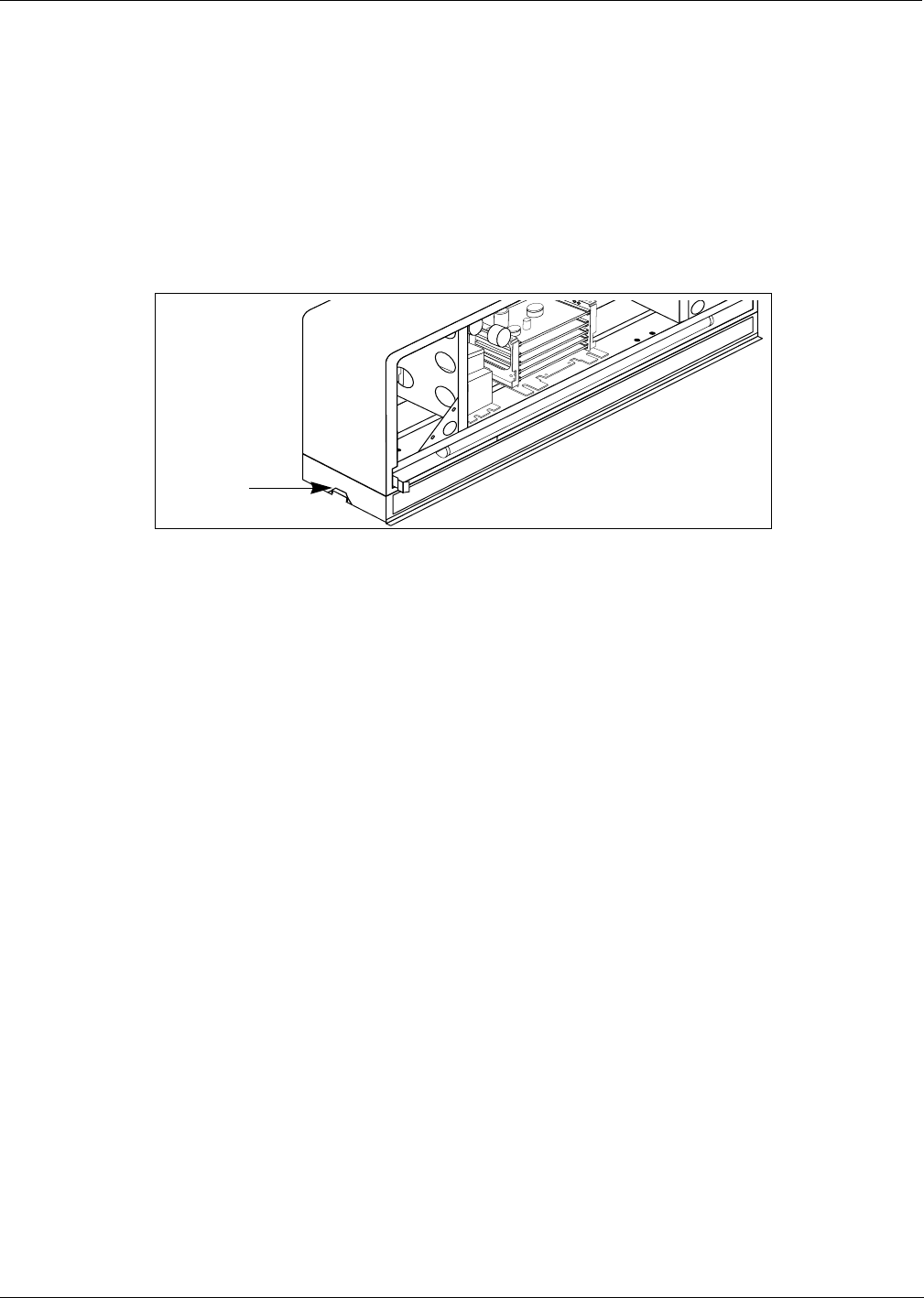
16 From ‘A’ side of unit, drop (lower) CRIND tray.
MDE-4063 TRIND TIRIS Retrofit Kit C00011-010-XXXX Installation Manual• August 2001 Page 31
Installation Instructions For The Advantage Series Units
Preliminary
08-24-01
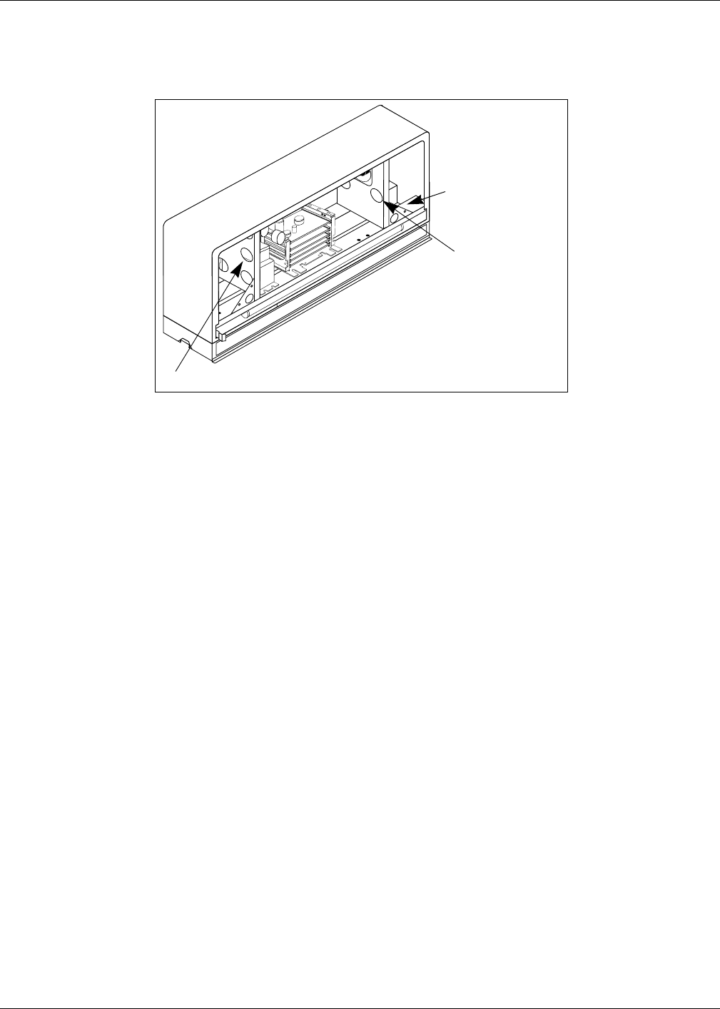
Installing Card Cage Assembly
Install card cage assembly from ‘B’ side of unit according to the following steps:
1Carefully pry out printer cable retainer from underside of printer shelf.
2Pull printer cable out of 2 3/4" round hole from bottom, and install piece of strip grommet
Q10315-06 around perimeter of hole.
3For all single-sided units, connect dummy load connector R20526-01 to JB on low frequency
transmitter PCB Q13579-01 in card cage. See “Card Cage Assembly T20606-G2” on page 62
for connection point.
4Install card cage assembly fuse side first on printer shelf and against center divider behind
right options door, as shown.
5Position card cage so that tab on upper left side of housing fits over latch cutout for main door
latch, securing card cage to divider.
6From ‘B’ side of unit, feed screw Q12083-13 and washer N16599-48 up through hole in shelf
into threaded hole in card cage bottom.
7Feed three prong female end of power supply cable R20580-G1 up through grommeted hole in
printer shelf to recessed receptacle on card cage assembly. Refer to “Card Cage Assembly
T20606-G2” on page 62 for connection points.
8Secure power cable R20580-G1 in cable retainer removed in Step 1, so that power cable and
printer cable are both secured, and reinstall cable retainer in grommeted hole.
9Feeding J182 ends of cables R20773-G2 for A and B sides up through grommeted hole and
connect P1 to J1 and P2 to J2 on T20662-G2 card cage harness.
10 Return printer to shelf and reconnect two printer cables and ground connector.
11 Reorient printer and secure to shelf.
Tab Card cage assembly
front side
Tab fits over cutout behind
door latch: see step 4
Card cage assembly location behind
right options door of 36" wide unit
Card cage assembly location behind
right options door of 48" wide unit
Tab
Installation Instructions For The Advantage Series Units
Page 32 MDE-4063 TRIND TIRIS Retrofit Kit C00011-010-XXXX Installation Manual• August 2001
Preliminary
08-24-01
Installing Transmitter Cables
Before proceeding be sure to be able to easily identify A and B side cable ends. Electric tape,
wire numbers or other suitable device may be used.
Note: Sharp bends in antenna cables will cause damage. All cable turns must be in loops and
gradual. Refer to “ASC TRIND Technology Update” on page 20.
1Feed P1A/B and /P3A/B ends of cable harness M00878A002 up through bulkhead grommet in
main cabinet.
2Be sure that there is sufficient length (24") of M00878A002 harness remaining in electrical
cabinet to reach connection points on card cage. Cables must be routed through underside of
card cage to connection points on ‘B’ side. See “Card Cage Assembly T20606-G2” on page 62
for connection points.
3Lay cable harness flat across top of main cabinet, through gusset opening to column as shown.
4Use electrical tape to secure cable harness flat to top of cabinet and in gusset opening. See
illustration above.
5Route cables from top of main cabinet up along inside of column, keeping cables flat and
parallel.
6Loop cable harness 3" down into space between column and main cabinet and back up again to
allow for reinstallation of inside sheathing.
Note: Turn in cables must be gradual, not sharp, to prevent damage to cables.
7Feed cables up through knockout openings in unit top cover.
PB
P2B
P2A
PA
P1B
P3B P3A
P1A
M00878A002 Cable Assembly
Cables fed through gusset
opening to column and up
inside of column.
Routing cables to
main cabinet
Cables
secured with
electrical
tape
MDE-4063 TRIND TIRIS Retrofit Kit C00011-010-XXXX Installation Manual• August 2001 Page 33
Installation Instructions For The Advantage Series Units
Preliminary
08-24-01
8Without removing upper piping housing sheathing, install piece of edge grommet Q10315-06
along edge of sheathing where cables pass in column. See exploded illustration below.
Note: Carefully check for any points along cable harness run where cables may come in
contact with sheet metal edges, and install edge grommet to prevent cable damage.
9Leave cable ends in upper housing.
10 Press cable harness flat and parallel to column and secure with electric tape as shown.
11 Install edge grommet Q10315-06 on bottom edge of inner sheathing and replace inner
sheathing, using screws saved during disassembly.
Edge grommet Q10315-06 to
protect cables from metal
edge of upper piping housing
sheathing
Installing edge grommet Exploded View:
Do Not Remove
Upper Piping
Housing
Sheathing From
Unit
Electrical tape
Sufficient cable
to make loop, not
sharp turn, back
up to top of main
cabinet. Sharp
bend will damage
cables
Strip grommet
Q10315-06 on
bottom edge of
inner
sheathing
Cables on column
shown without
main cabinet
cable ends in upper housing
Installation Instructions For The Advantage Series Units
Page 34 MDE-4063 TRIND TIRIS Retrofit Kit C00011-010-XXXX Installation Manual• August 2001
Preliminary
08-24-01
Replacing Main Cabinet Top Cover
1Use hacksaw to cut 3/8" slots in cabinet top cover to allow strip a minimum of 6" wide to be
folded back with pliers and hammered flat as shown, to allow cables to pass under top cover to
grommet.
Note: Remove top cover from work area to cut slot. Do not cut metal in proximity to
dispensers. Place top cover on cardboard while hammering to prevent damage to paint.
2Clean edges and burrs around cuts in cover with file or deburring tool.
3Thoroughly seal spaces around and between cables in main cabinet bulkhead grommet with
RTV sealant.
Note: Place some packaging plastic inside bulkhead grommet from top to prevent sealant from
running out bottom when applied.
Routing R20773-G2 Cables
Note: Retrofit kit comes with ten (10) adhesive-backed cable clamps (Q13558-04). Note the
following variations for routing cables to main cabinet:
Horse Shoe style CRIND Device
For these units, utilize opening in printer shelf bottom for routing.
6” strip
hammered flat
under top cover
cables
Slotting top cover
Horse Shoe style
CRIND device
Printer shelf
Horse shoe style module
Opening for cable
routing
MDE-4063 TRIND TIRIS Retrofit Kit C00011-010-XXXX Installation Manual• August 2001 Page 35
Installation Instructions For The Advantage Series Units
Preliminary
08-24-01
Pull Out CRIND Tray
For these units utilize round 2-3/4" hole in printer shelf bottom, used for printer cable. Use
cable clamps to secure cables to underside of printer shelf.
Cable Routing Along Option and Main Doors
When routing door cables to card cage, leave excess cable on door, routing cable around edges
of printed circuit board.
Note: It is critical that door cables do not get crimped or pulled when either options door or
main door are opened or closed. Be sure that door cables are secured such that they
cannot be caught in main door. when door is closed, and always close main door before
options door.
1Remove option door shield
2Connect J182 connectors on R20773-G2 cables to P182 on Light/Microreader PCB for each
side right options door.
3Loosely secure cables using tie wrap Q10178-01 and hole on indicator light printed circuit
board.
4Leaving sufficient cable to reach connection points on card cage, use clamps to secure cables
to underside of lighting frame. Be sure clamps are secured to non-removable part of frame, so
access is maintained for lighting service.
Printer shelf with
2-3/4" round hole
Pull out CRIND
electronics tray
Pull Out
CRIND Tray
Indicator light
PCB T20601
P182 connection
and cable route
Hole to secure cable
with tie wrap
Hole to secure cable with tie wrap
R20773-G2 cable
Installation Instructions For The Advantage Series Units
Page 36 MDE-4063 TRIND TIRIS Retrofit Kit C00011-010-XXXX Installation Manual• August 2001
Preliminary
08-24-01
5Ensure that option door opens and closes freely without stressing or crimping cables, use tie
wrap Q10178-01 to loosely secure cables to small fixed tab at end of light frame, forcing
cables between light frame and door gasket.
6Secure J1/J2 end of each R20773-G2 cable to existing cable clamp (for door cabling) just
inside main cabinet, allowing enough slack for main door to open and close freely without
pulling on or crimping cable. See illustrations below and on next page.
Attach clamps and
cables to underside
of panel light frame
Loosely secure
cables to tab on
light frame with
tie wrap
R20773-G2 Cable routing on
option door
Secure cable
to existing
door cable
clamp
MDE-4063 TRIND TIRIS Retrofit Kit C00011-010-XXXX Installation Manual• August 2001 Page 37
Installation Instructions For The Advantage Series Units
Preliminary
08-24-01
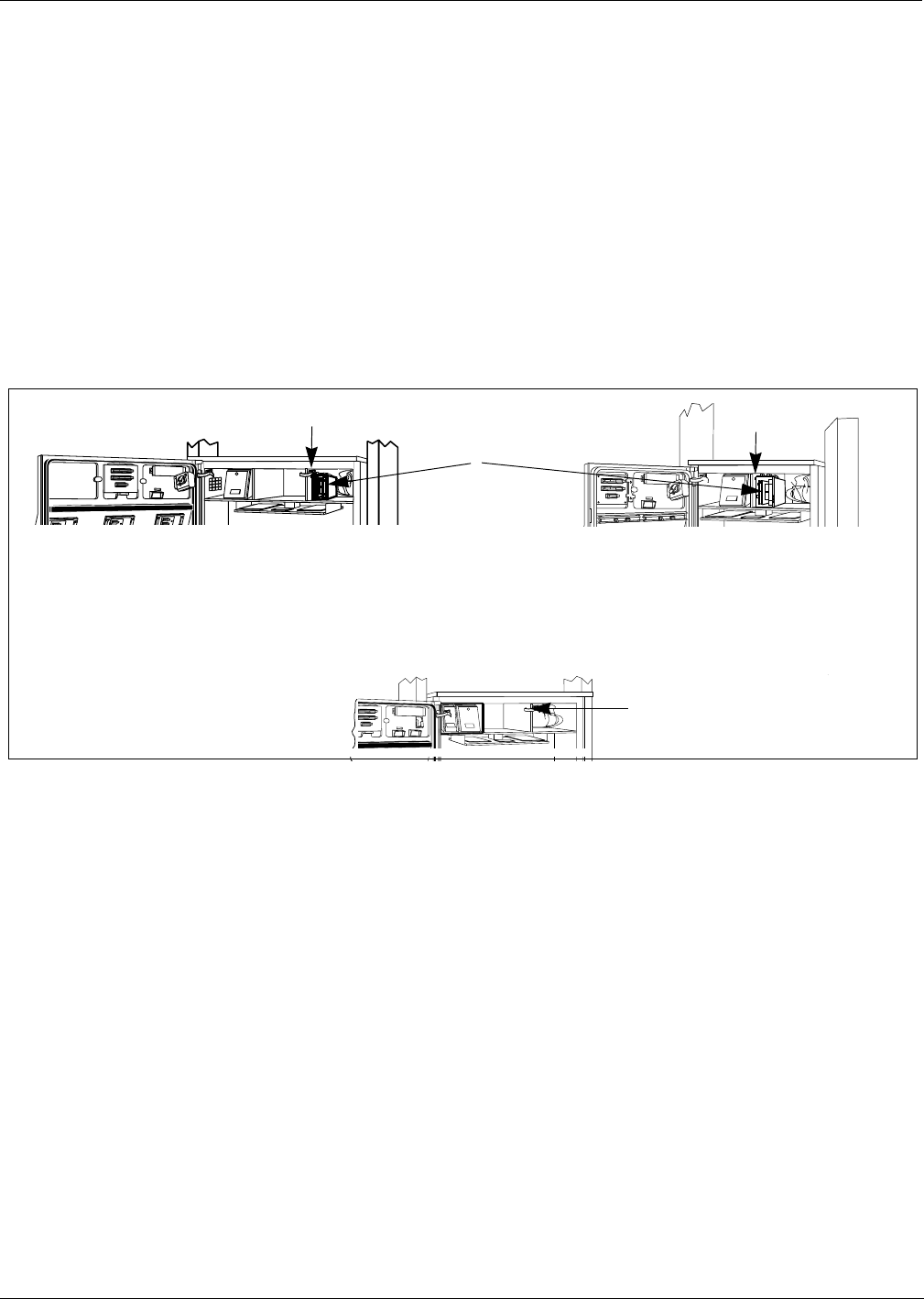
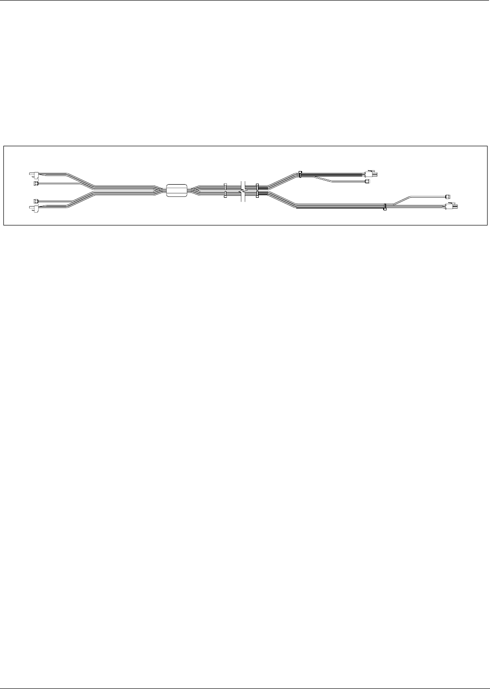
T20662-G2 Cable Routing In Main Cabinet
Card Cage cable harness T20662-G2 contains two cables with connectors P1 and P2. P1 for A
Side is shorter of the two. Each cable is designed to extended to the point where the main door
and electronics cabinet are hinged. Feed cables through 2-3/4" round hole in printer shelf.
Go to “Preparing Antenna Cable Connections” on page 49.
Stress or
crimping
point for
cables
Use clamps
to secure
cables to
underside of
shelf
A Side
Use clamps to
secure cables to
underside of
shelf
2-3/4"
round hole
for printer
cable
T20662-G2
cable routing
from card
cage under
printer shelf
B Side
B Side
A Side
Viewed from above
T20262-G2
cable fed
under shelf
through
grommeted
2 3/4’’ hole
door cable
clamp
R20773-G2 cable
P2/J2
card
cage
kit cable
clamps
P1/J1
cable clamps under shelf
R20773-G2 cable
kit cable clamps
J182/P182
J182/P182
Installation Instructions For MPD-3 Units
Page 38 MDE-4063 TRIND TIRIS Retrofit Kit C00011-010-XXXX Installation Manual• August 2001
Preliminary
08-24-01
Installation Instructions For MPD-3 Units
Before beginning read “Classifying Hazardous Locations” on page 19 and “ASC TRIND
Technology Update” on page 20.
The TRIND™ retrofit can only be done on MPD-3 units with CRIND™ printer on left.
Preparing For Installation
1From ‘A’ side, remove left column outside sheathing (or top section only for two piece
sheathing).
2Temporarily secure inner sheathing to frame using tape.
3Open main access door. Refer to MDE-2531 for instructions.
Outside sheathing -
left column
A side
MDE-4063 TRIND TIRIS Retrofit Kit C00011-010-XXXX Installation Manual• August 2001 Page 39
Installation Instructions For MPD-3 Units
Preliminary
08-24-01
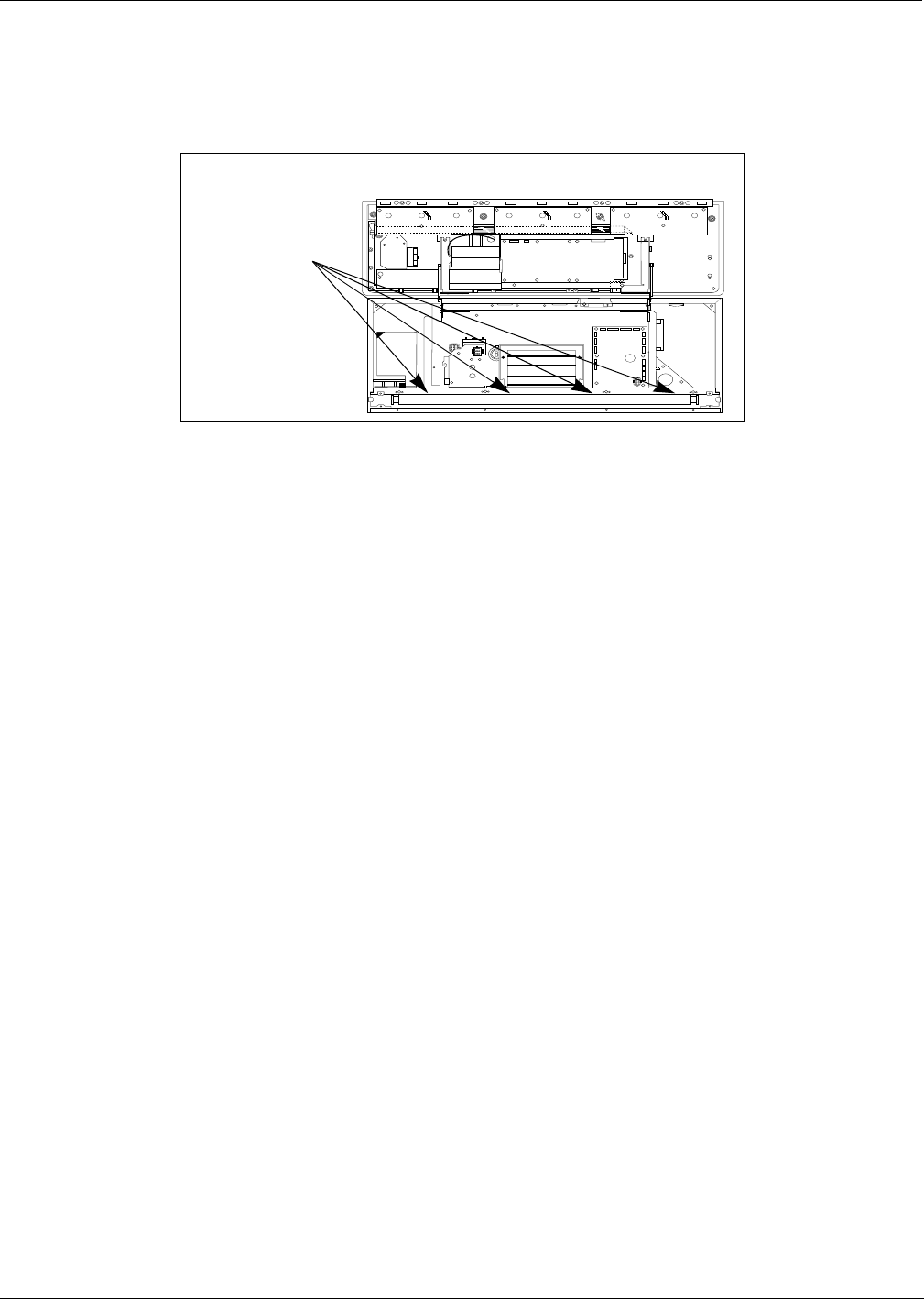
Removing Main Cabinet
1Locate four nuts on each side of main cabinet, ‘A’ and ‘B’, that secure cabinet to frame.
2Remove all eight nuts and washers, and save for reassembly.
3Disconnect barrel connectors to allow cabinet to be removed from unit.
Note: If barrel connectors are mounted to holding plate(s), remove plates and discard.
4Carefully lift cabinet up and off studs, and remove from fuel island.
5Remove inner sheathing on left column (viewed from ‘A’ side). Set sheathing and screws aside
for reassembly. See illustration below.
Note: For units with VaporVac®, VaporVac pan does not need to be removed. Sheathing can be
carefully pulled out from center until top bends clear of pan.
+
+
+
++
+
+
+
+
+
+
+
+
+
+
+
+
+
+
+
+
+++
+
+
++
++
+
+
++
+
+
+
Four nuts each side, ‘A’
and ‘B’, on mounting
studs behind lip
Removing main cabinet
Installation Instructions For MPD-3 Units
Page 40 MDE-4063 TRIND TIRIS Retrofit Kit C00011-010-XXXX Installation Manual• August 2001
Preliminary
08-24-01
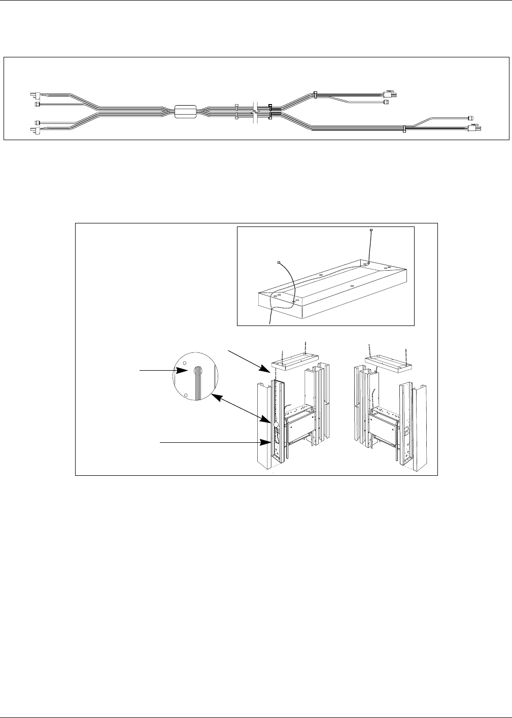
Installing Transmitter Cables
Before proceeding be sure you can easily identify A and B side cable ends. Electric tape, wire
numbers or other suitable device may be used as needed.
Note: Sharp bends in antenna cables will cause damage. All cable turns must be in loops and
gradual. Refer to “ASC TRIND Technology Update” on page 20.
1Feed cable ends PA/B and P2A/B (see illustration above) down from upper piping housing
into left column seen from ‘A’ side. Leave a minimum of 12'' of cable in upper housing.
2Feed cables down between piping brackets and inside column.
3There are several holes in column above or below main cabinet level, approximately 7/16" in
diameter. Locate hole that provides access for using knockout and is most closely aligned with
bottom of cabinet, and open hole to 7/8" diameter or larger.
Note: Various units have different holes and configurations. Any hole on column, square,
rectangular or round, of sufficient size or made so with knockout can be used for cables.
4Use rounded file or deburring tool to round edges of hole. Cover edges of hole with electric
tape.
5Loop cables below hole and back up through hole and out of column.
M00878A002 Cable Assembly
cables connections to card cage cable connections for upper housing
PB
P2B
P2A
PA
P1B
P3B P3A
P1A
Cable harness
Harness looped
in column
Routing M00878A002 cable
harness to main cabinet
Harness fed
up through
hole
enlarged
using
knockout
M00878 cable assembly splitting
inside upper housing to exit
through two knockouts
MDE-4063 TRIND TIRIS Retrofit Kit C00011-010-XXXX Installation Manual• August 2001 Page 41
Installation Instructions For MPD-3 Units
Preliminary
08-24-01
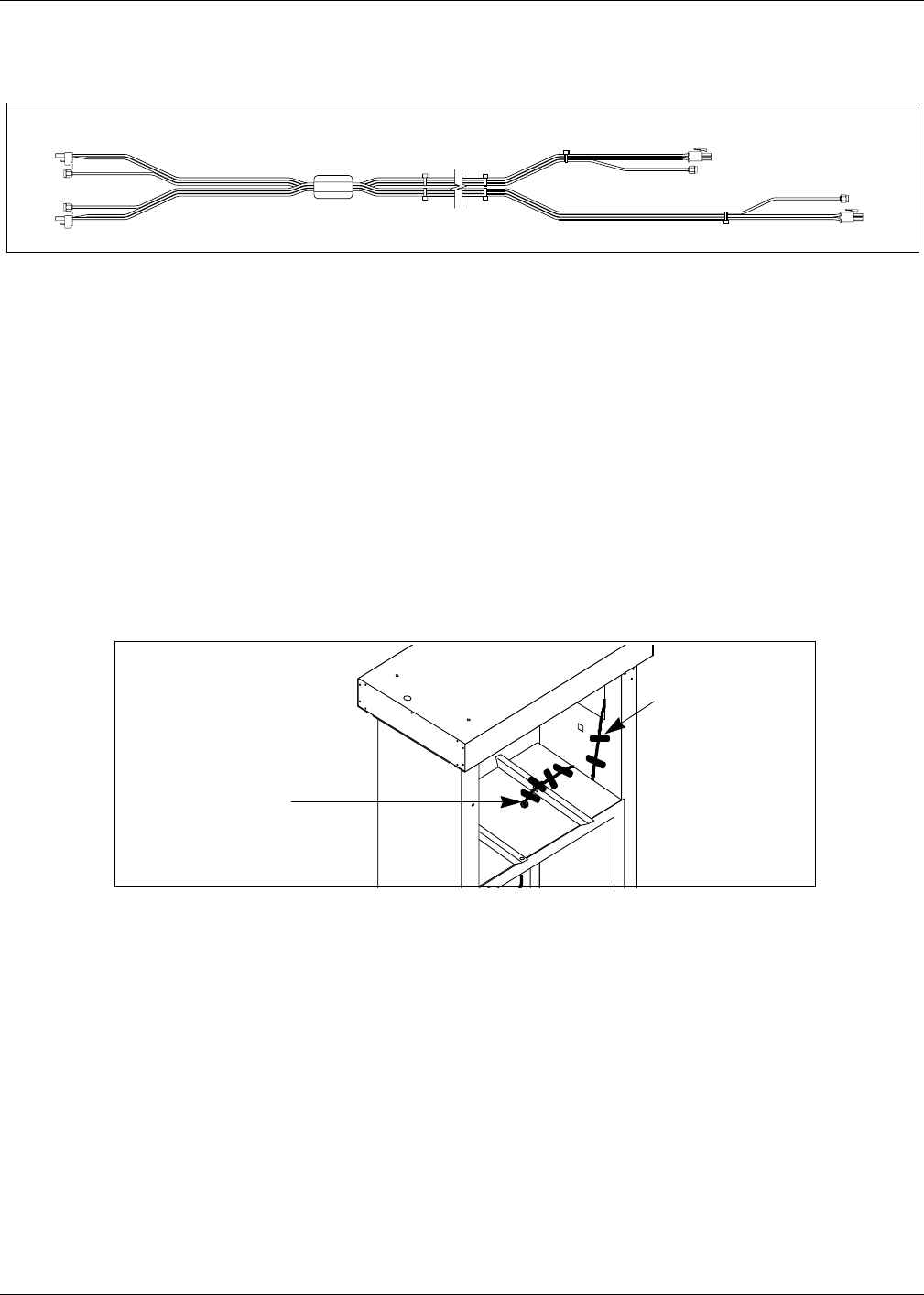
6Feed cable ends into vapor barrier, dressing and securing cables in place with electrical tape.
7Away from island, use snips or shears to cut slits 1-1/2" apart in bottom center of inside
sheathing at 45 degree angles. See illustration below.
8Fold pieces forward on cabinet side of sheathing. Use hammer to flatten folded pieces as
shown.
9Reposition inner sheathing and tape in place, being sure that cables pass through opening at
bottom.
10 Replace outside sheathing, and remove tape from inner sheathing.
11 Dress and secure cables on cabinet top with electrical tape.
Notching inner sheathing
Step 7:
Cut two slits 3/8"
deep at 45 degree
angle approximately
1 1/2" apart in
bottom center of
sheathing
Step 8: Use pliers to fold pieces in direction of cabinet
and away from column. Use hammer to flatten
Finished inner
sheathing - side
facing main cabinet
Installation Instructions For MPD-3 Units
Page 42 MDE-4063 TRIND TIRIS Retrofit Kit C00011-010-XXXX Installation Manual• August 2001
Preliminary
08-24-01
Removing Faceplate
MPD-3 units have two types of faceplates; slide-in (PMI bezel) and bolt-on (Mack bezel).
Follow directions for the type of faceplate and bezel that applies.
For units with slide-in faceplates on PMI bezels, do the following:
1 Release right side faceplate using keyswitch.
2Open manager keypad door and remove single screw.
3Gently force faceplate up, and slide tip of knife or flat blade screwdriver under bottom edge of
faceplate.
4Pry bottom of faceplate away from unit, until faceplate can be removed from unit.
5Dispose of faceplate.
For units with bolt-on faceplates on Mack bezels, do the following:
1Open bezel door and lift until door is latched open.
2Disconnect cable between manager keypad and logic board on bezel door, and discard cable.
3Locate six sets of nuts and washers on studs securing faceplate to bezel door, and remove
hardware.
Note: This may require removing mounting hardware from price per unit (PPU) and CRIND
logic boards to gain access.
4Remove 6 sets of nuts and washers from faceplate studs and remove faceplate. Dispose of
hardware and faceplate.
5With putty knife, remove keypad door gasket and any adhesive residue.
Screw
Removing faceplate
Stud locations behind faceplate
Stud locations behind faceplate
Faceplate stud
locations on
Mack bezels
MDE-4063 TRIND TIRIS Retrofit Kit C00011-010-XXXX Installation Manual• August 2001 Page 43
Installation Instructions For MPD-3 Units
Preliminary
08-24-01
Routing Cables into Main Cabinet
1Open bezel doors on main cabinet.
2Locate indent on rear of door behind 3/4" diameter unopened access point.
3Use 3/4" drill bit to open hole in plastic door from rear of door.
Note: If electric drill is used work must be 20’ from fuel island.
4Use deburring tool or file to round edges of hole.
5On left side of main cabinet (viewed from ‘A’ side), in center bottom of wrapper, use snips to
cut two 3/8" slits at 45 degree angle.
Note: Slots and folds duplicate those done on inner sheathing. See illustration on page 41.
6Fold pieces out from cabinet and press flat against wrapper from outside.
7Carefully return cabinet to unit, and lower cabinet on to studs.
8Feed cables up into cabinet under slot made in wrapper.
9Secure cabinet in place with nuts and washers removed with cabinet.
10 Heavily seal around cable entry slot with RTV sealant from inside cabinet.
11 Reconnect barrel connectors.
Center of left side
wrapper, slotted for
cable feed
Reinstalling main
cabinet
Installation Instructions For MPD-3 Units
Page 44 MDE-4063 TRIND TIRIS Retrofit Kit C00011-010-XXXX Installation Manual• August 2001
Preliminary
08-24-01
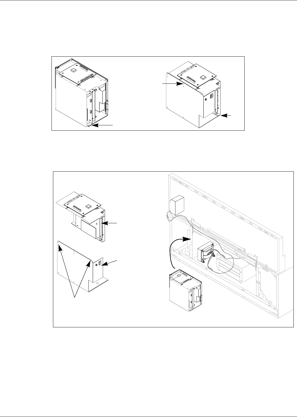
Installing Card Cage Assembly
Install card cage assembly from ‘A’ side of unit, according to the following steps:
1Begin to separate card cage assembly into two pieces by removing one screw on top and two
nuts at bottom, one each front and rear.
2Disconnect cables joining two sides of card cage.
3From ‘A’ side, place bottom section of card cage fuse side first on to left shelf.
4Reassemble card cage using nuts removed in Step 1 and two (2) tie wraps in place of screw
and reconnect cables.
5For all single-sided units, connect dummy load connector R20526-01 to JB on transmitter
PCB. See “Card Cage Assembly T20606-G2” on page 62 for connection point.
Screw
Nut
Nut
Card cage
assembly
+
+
+
+
Installing disassembled
card cage
Card cage installation location from ‘A’ side
Bottom section of
card cage, fuse side
Top section of
card cage
Tie wraps (2) at each corner
to reassemble card cage
rather than screw

MDE-4063 TRIND TIRIS Retrofit Kit C00011-010-XXXX Installation Manual• August 2001 Page 45
Installation Instructions For MPD-3 Units
Preliminary
08-24-01
6For units with Screened Image Display (SIDs) only, do the following:
Note: If these directions are not followed printed circuit boards will be damaged.
•From ‘B’ side of unit, install screw up through hole under card cage. Align screw with
mounting hole on card cage, but do not fasten.
•Tilt card cage away from screw, and secure screw to shelf by installing two nuts under
card cage.
•Let card cage rest on nuts with screw protruding up through hole in card cage.
Note: This will result in card cage tilting down toward the ‘A’ side.
7For all units, from ‘A’ side of unit, fasten card cage to shelf using 6-32 x 3/8" screw (Q12083-
13) supplied with kit.
Installation Instructions For MPD-3 Units
Page 46 MDE-4063 TRIND TIRIS Retrofit Kit C00011-010-XXXX Installation Manual• August 2001
Preliminary
08-24-01
Installing TRIND Faceplate Assembly.
Perform the following steps for each side of unit.
For installing TRIND slide-in faceplates on PMI bezels, do the following:
1Remove new TRIND faceplate assembly from box. For ‘B’ side faceplates only, feed faceplate
cables back into faceplate housing through round hole in shield to shorten cable leads.
Note: ‘B’ side cables have a shorter run to card cage than ‘A’ side.
2Peel adhesive backing off round gasket N23881-01. Install gasket adhesive side first to sheet
metal shield on back of faceplate to form seal around hole for cables on faceplate assembly.
3Peel paper backing off adhesive strip on rectangular locking plate N23873-G1 and install plate
along top lip of manager keypad recess.This plate provides a bearing surface for lock cam on
new TRIND faceplate.
4Feed ends of cables R20773-G2 through 3/4 inch hole on bezel door drilled in Step 3 of
“Routing Cables into Main Cabinet” on page 43. Pull slack cable through hole.
5Follow these directions to install new TRIND faceplate:
•Feed top edge of faceplate in to groove on top of door.
•Gently push bottom of faceplate in until faceplate drops into bottom groove.
Note: Faceplate may be tight fit. If needed, with faceplate forced up into top groove, firmly hit
faceplate along bottom edge with palm of hand until faceplate is in bottom groove.
•Secure in place with keylock.
6Refer to MDE-2620, Graphics Panel Application for instructions on installing graphics.
For installing TRIND™ bolt-on (stud type) faceplates, do the following:
1Remove new TRIND faceplate assembly from box. For ‘B’ side faceplates only, feed faceplate
cables R20773-G2 back into faceplate housing through round hole in shield to shorten cable
leads.
Note: ‘B’ side cables have a shorter run to card cage than ‘A’ side.
2Remove existing manager keypad from bezel door, and use putty knife to remove keypad
gasket and adhesive residue from door.
3Replace the door gasket removed in step 2 with adhesive backed gasket Q11659-01.
Locking plate N23873-G1
with adhesive backing
Installing
locking
plate
MDE-4063 TRIND TIRIS Retrofit Kit C00011-010-XXXX Installation Manual• August 2001 Page 47
Installation Instructions For MPD-3 Units
Preliminary
08-24-01
4Replace existing keypad and keypad cable with T17549-G1 keypad and long cable R18163-
G1, but do not install keypad on bezel door.
Note: At user’s discretion, new keypad can be placed behind brand panel lighting or in the
well behind the printer door, on either side of printer, provided cable is run and secured
properly and safe access is maintained.
5Remove yellow tape on back of bezel door covering round hole.
6Peel adhesive backing off round gasket N23881-01. Install gasket adhesive side first to seal
around hole on back of bezel door.
7Feed ends of cables R20773-G2 through 3/4" hole on door and pull slack cable through hole.
8Install 6 split spacers K87404-01 on the faceplate side of the bezel door, in the mounting holes
for the faceplate. See illustration on this page.
9Install faceplate assembly T17534-XX securing in place from back side of bezel door using in
this order:
•6 adhesive backed gaskets, Q11659-01.
Note: Do not remove paper backing on adhesive side, and install paper side to bezel door.
•6 flat washers, N16599-01
•6 self-locking nuts, Q10218-04
10 Refer to MDE-2620, Graphics Panel Application for instructions on installing graphics.
11 Peel paper backing off adhesive strip on rectangular locking plate N23873-G1 and install plate
along top lip of manager keypad recess.This plate provides a bearing surface for lock cam on
new TRIND faceplate.
TRIND faceplate
BezelFaceplate
stud
Split spacer Gasket, adhesive
backed with paper left
on and facing bezel
Washer
Nut
Faceplate mounting hardware
Locking plate N23873-G1
with adhesive backing
Installing
locking
plate
Installation Instructions For MPD-3 Units
Page 48 MDE-4063 TRIND TIRIS Retrofit Kit C00011-010-XXXX Installation Manual• August 2001
Preliminary
08-24-01
Routing Cables in Main Cabinet
Kit comes with ten cable clamps (Q13558-04).
Install strip grommet Q10277-02 in 1-1/2" hole for power cable R20850-01.
Note: Route cables on ‘B’’ side to card cage so that all cables are between card cage and
shelf where possible, or door will not close without potential damage to cables or
hardware.
Routing cables in
main cabinet
Existing snap-in 1 1/2" bushings- use for routing
Bundle cables
between shelf wall
and card cage,
using clamp
‘B’ side
Install Q10277-02
strip grommet for
power cable
R20580-G1
MDE-4063 TRIND TIRIS Retrofit Kit C00011-010-XXXX Installation Manual• August 2001 Page 49
Preparing Antenna Cable Connections
Preliminary
08-24-01
Preparing Antenna Cable Connections
For all units, gain access to upper housing from underside, by removing upper housing bottom
sheathing or VaporVac belly pan, as required. Refer to MDE-2531 Service Manual for
instructions. Save all parts and hardware for reassembly. For
For additional information refer to “Cable Block Diagram R20762” on page 60 and “Cabinet
Cable Connections” on page 61.
Do the following:
1Locate previously installed P1A/B and P3A/B ends (4 total) of cables on cable harness
M00878A002 in upper housing.
2Be sure that all connectors can be identified for A and B sides, respectively.
Upper Housing Connections
Do the following to connect M00878A002 cable harness assembly to antenna:
1For A Side, inside upper housing:
•Connect P1A on harness to J1 low frequency antenna cable.
•Connect P3A on harness to J2 high frequency antenna cable.
2For B Side, inside upper housing:
•Connect P1B on harness to J1 low frequency antenna cable.
•Connect P3B on harness to J2 high frequency antenna cable.
3Use tie wraps supplied with kit to secure cables to frame in upper housing, away from
maintenance access areas for piping and valves.
M00878A002 Cable Assembly
PB
P2B
P2A
PA
P1B
P3B P3A
P1A
Preparing Antenna Cable Connections
Page 50 MDE-4063 TRIND TIRIS Retrofit Kit C00011-010-XXXX Installation Manual• August 2001
Preliminary
08-24-01
Assembling Antenna Mounting Brackets
Use saw horse, work bench or even packaging boxes as platform to assemble antenna related
parts on a flat surface. Use packaging materials under parts to protect against dirt or scratches.
Assemble antenna and universal mounting brackets at ground level according to the following
steps.
Note: If power tools are used for assembly, work must be done at least 20’ from fuel island.
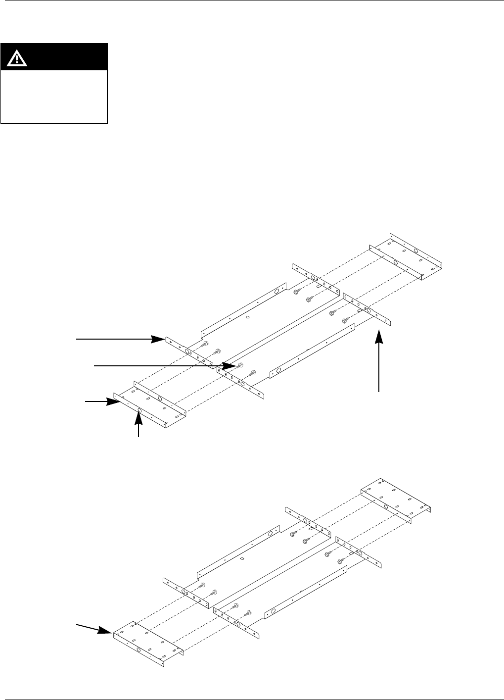
1For assembly detail for 48" or 36" wide units, with or without light box, see Figures 6 (48") on
page 50 or Figure 8 on page 51 for (36").
Note: For single-sided units, antenna bracket T20211-03 does not have antenna mounting
arms; it has straight lip that goes to unit side without antenna.
If power tools are used
for assembly work must
be done at least 20" from
fuel island
CAUTION
Figure 8: Assembling universal and antenna brackets for The Advantage Series 48" (wide) frame units
48" wide unit without logo display cabinet
48" wide unit with logo display cabinet
Universal bracket
(T20212-01)
Antenna bracket
(T20211-03)
Self-threading screws
(K85736-45)
Invert universal
brackets as shown
to provide platform
for logo display
cabinet.
Holes (2 per bracket)
for grommets N15941-38
Note: for single-sided units
antenna bracket T20211-03 does
not have antenna mounting arms
MDE-4063 TRIND TIRIS Retrofit Kit C00011-010-XXXX Installation Manual• August 2001 Page 51
Preparing Antenna Cable Connections
Preliminary
08-24-01
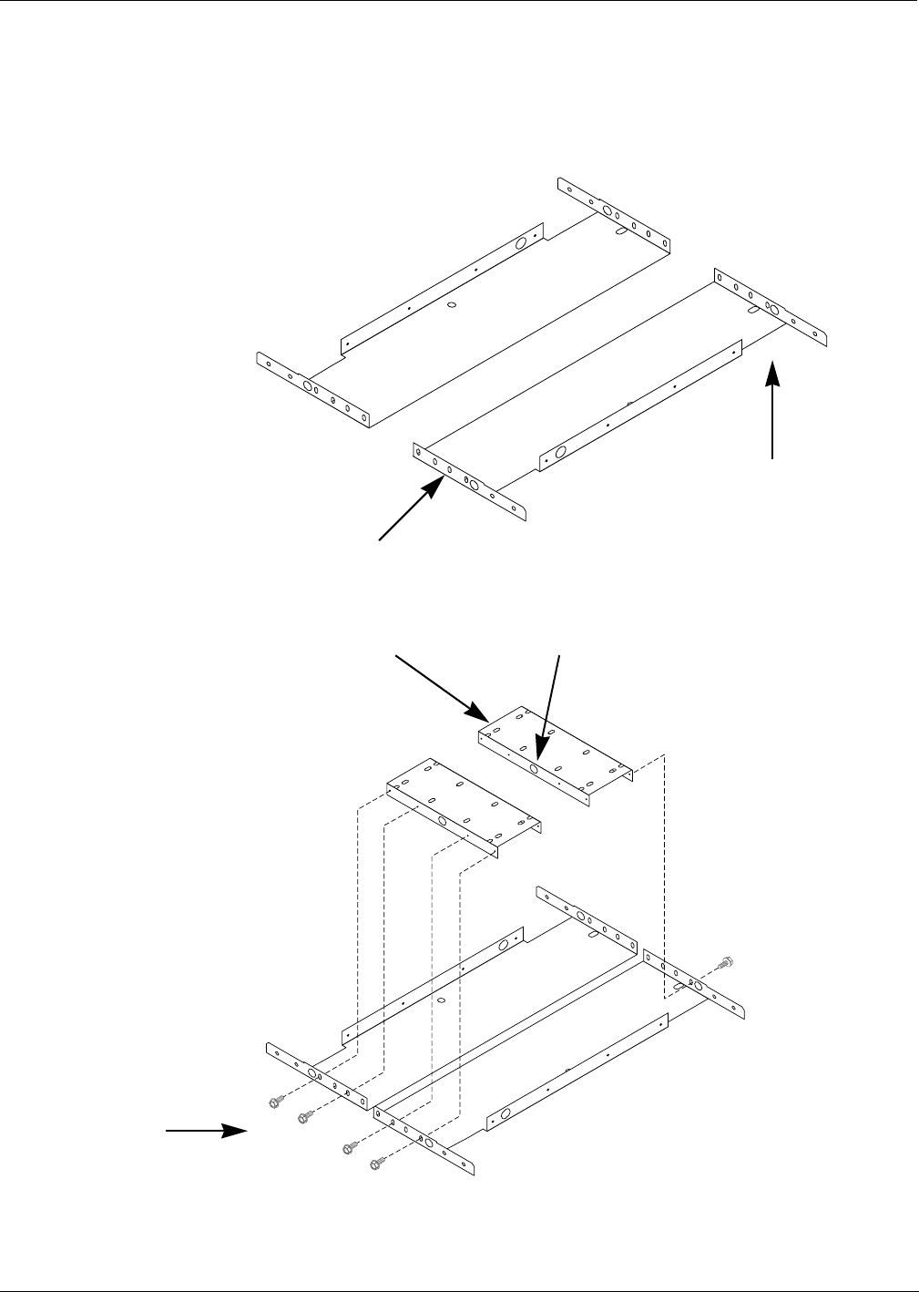
Figure 9: Assembling universal and antenna brackets for The Advantage Series 36" (narrow) frame units
36" wide unit without logo display cabinet
36" wide unit with logo display cabinet
Use antenna brackets
without universal brackets
Invert universal
brackets
so flat side is up, to
provide
platform for logo
display cabinet.
Antenna bracket
(T20211-03)
Self-threading screws
(K85736-45)
Universal bracket
(T20212-01)
Holes (2 per bracket)
for grommets N15941-38
Note: for single-sided units
antenna bracket T20211-03
does not have antenna
mounting arms
Preparing Antenna Cable Connections
Page 52 MDE-4063 TRIND TIRIS Retrofit Kit C00011-010-XXXX Installation Manual• August 2001
Preliminary
08-24-01
2 For all installations requiring both antenna and universal brackets, fasten universal brackets to
antenna brackets using self-threading screws (K85736-45) from antenna bracket side.
3Install two round grommets (N15941-38) in two holes on only one universal bracket. See
Figure 12 on page 55.
4Lift complete bracket assembly and place on top of unit, aligning mounting holes with four
tapped holes (3/8-16) on top of unit and keeping grommeted universal bracket to grommeted
side of top cover.
Note: Use RTV sealant supplied with kit to seal both around base of all mounting holes and
non-mounting holes where hardware must be reinstalled. Where holes are under or go
through bracket assembly, apply sealant under assembly, between it and top cover for
water seal.
5If unit does not have logo display cabinet, secure bracket assembly to unit using four bolts and
washers removed with hoisting brackets and saved for reassembly in Step 1 of “Preparing For
Installation” on page 22.
6If unit does have logo display cabinet, loosely (hand tight) thread four pieces of threaded rod
N23880-01 provided in ASC TRIND™ tool kit into four tapped holes to keep parts from
slipping while logo display cabinet is re-installed.
Note: Threaded rods will keep antenna bracket assembly aligned properly as logo display
cabinet is positioned.
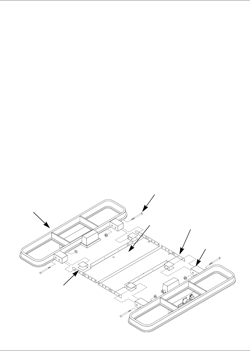
7Position arms of antenna assembly T20231-G1 between matching arms on antenna brackets.
See Figure 8.
8Install two 4" bolts (K01914-70) and nuts (Q11890-08) on each two bolt antenna mount. See
Figure 10.
K01914-70 bolt, 1/4" x 4" - one
of two for each mount shown
Overhead antenna
assembly T20231-G1
Figure 10: Fastening overhead antenna
assembly to bracket assembly
Antenna arm
support on
bracket
R20620-01
Antenna bracket
T20211-01
Antenna
mounting arm
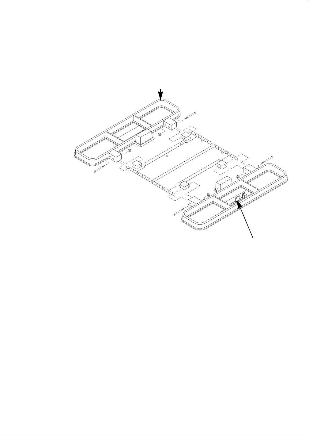
MDE-4063 TRIND TIRIS Retrofit Kit C00011-010-XXXX Installation Manual• August 2001 Page 53
Preparing Antenna Cable Connections
Preliminary
08-24-01
Mounting High Frequency Antenna
Mount high frequency antenna to plastic antenna housing from bottom according to the
following steps.
1Locate two pre-drilled holes in bottom of plastic antenna housing, and align high frequency
antenna mounting bracket to holes, with cable fitting facing towards unit.
2Secure in place with two screws provided with high frequency antenna.
3Remove antenna connection box cover and save cover and screws for reassembly.
Figure11:
Installing high frequency antenna
Plastic antenna
housing
High frequency
antenna
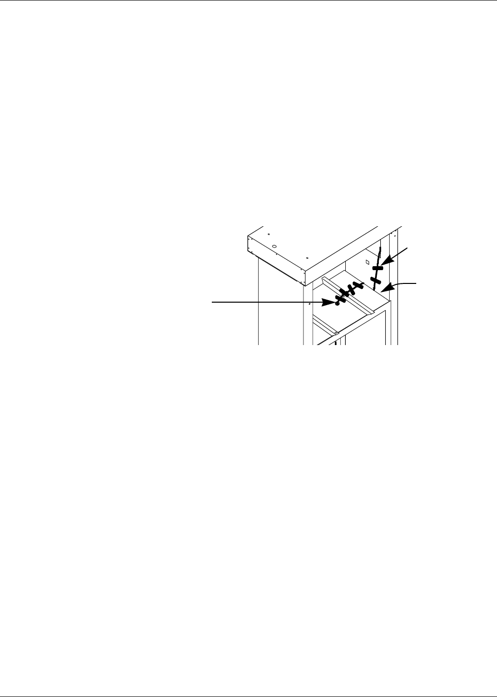
Preparing Antenna Cable Connections
Page 54 MDE-4063 TRIND TIRIS Retrofit Kit C00011-010-XXXX Installation Manual• August 2001
Preliminary
08-24-01
Installing Transmitter Cables
Before proceeding be sure to mark both ends of one of two R20509-G2 cables and one of two
Q13578-01 cables to be identified as ‘A’ side. Electric tape, wire numbers or other suitable
device may be used.
Note: Sharp bends in antenna cables will cause damage. All cable turns must be in loops and
gradual. Refer to “ASC TRIND Technology Update” on page 20.
1Feed two pin connector end of two R20509-G2 cables and black ends of two Q13578-01
cables up through bulkhead grommet in main cabinet.
2Be sure that there is sufficient length (24") of all four cables to reach connection points on card
cage. Cables must be routed through underside of card cage to connection points on ‘B’ side.
See “Card Cage Assembly T20606-G2” on page 62 for connection points.
3Lay cables flat across top of main cabinet, through gusset opening to column as shown in
Figure 12.
4Locate points on R20509-G2 cables (39" from PA/B connector) where cables shield has been
stripped for a space of between 1" and 2".
Note: There are two such points on each R20509-G2 cable, one at 21" and one at 39" from
PA/B connector. Disregard the stripped point closest (21") to PA/B.
5Position stripped section of R20509-G2 cable(s) so it is approximately one inch clear of the top
of main cabinet and main cabinet top cover when cover is replaced later.
6Use tie wrap or electrical tape to loosely bind cables together at gusset opening.
7Use electrical tape to secure cables flat to top of cabinet and in gusset opening. See Figure 12.
8Route cables from top of main cabinet up along inside of column, keeping cables flat and
parallel. See Figure 15 on page 55.
9Loop cables 3" down into space between column and main cabinet and back up again to allow
for reinstallation of inside sheathing. Be sure that stripped section of R20509-G2 cable(s) will
be in the air between the main cabinet and column sheathing, and not under cabinet top cover
or behind inner sheathing when replaced. See Figure 12.
Note: Turn in cables must be gradual, not sharp, to prevent damage to cables.
10 Feed cables up through grommet in unit top cover and through grommets in universal bracket
being sure that there is sufficient cable length to reach connection points in antenna connection
box and on high frequency antenna assembly. See Figure 14 on page 55.
Cables fed through gusset
opening to column and up
inside of column.
Figure 12:
Routing cables to
main cabinet
Cables
secured with
electrical
tape
Stripped section
of R20509-G2
cable(s) in loop
between main
cabinet and
column
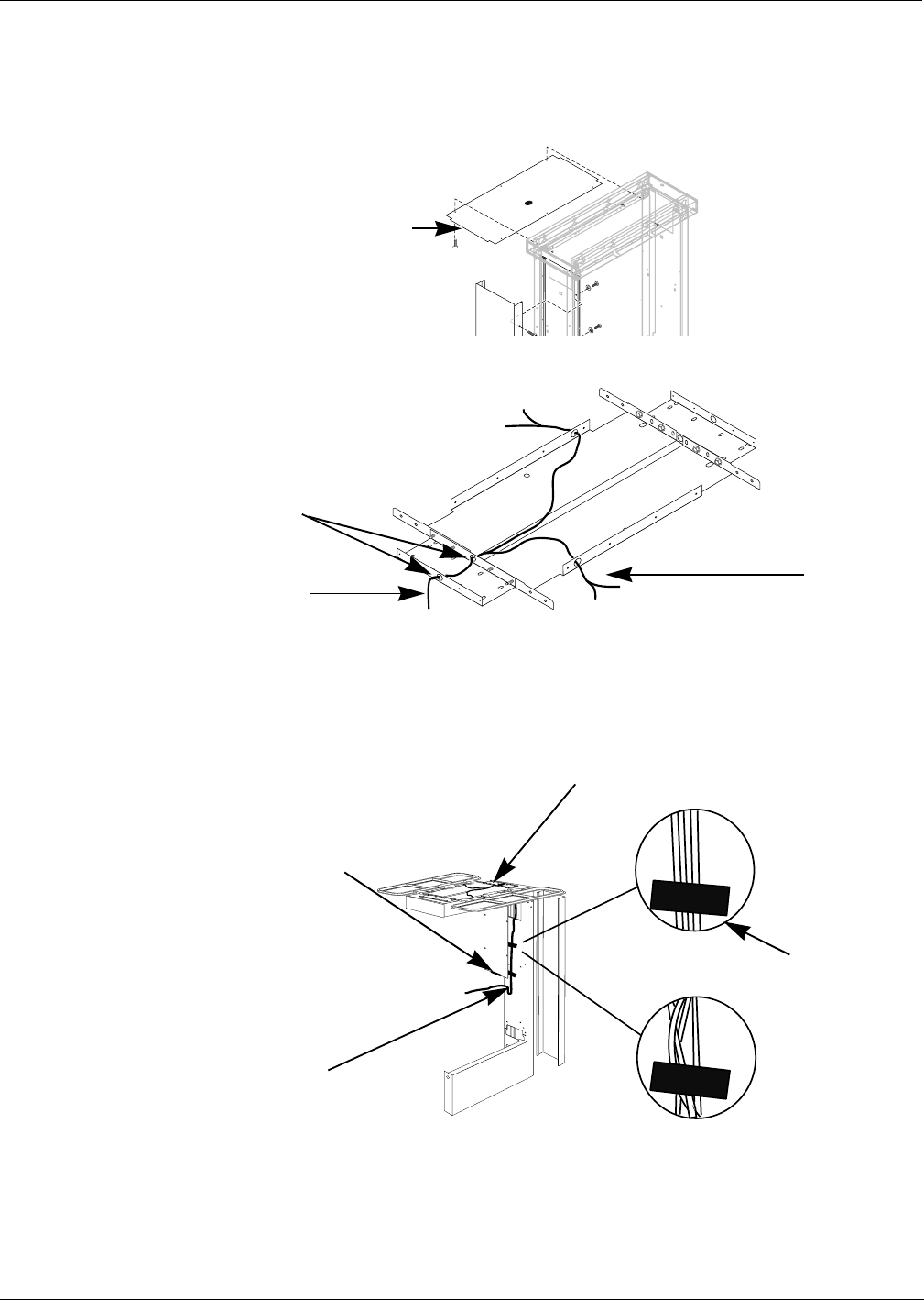
MDE-4063 TRIND TIRIS Retrofit Kit C00011-010-XXXX Installation Manual• August 2001 Page 55
Preparing Antenna Cable Connections
Preliminary
08-24-01
11 Without removing top sheathing, install piece of edge grommet Q10315-06) along edge of top
sheathing where cables pass in column. See exploded view in Figure 13.
Note: Carefully check for any points where cables are run where cables may come in contact
with sheet metal edges, and install edge grommet to prevent cable damage.
12 Be sure that cables marked for ‘A’ side go to that side, and other pair to ‘B’ side.
13 Lay cables flat and parallel to column and secure with electric tape as shown in Figure 15.
14 Install edge grommet Q10315-06 on bottom edge of inner sheathing (see Figure 15), and
replace inner sheathing, using screws saved during disassembly.
Note: Be sure that section of R20509-G2 cable with stripped shield is in the air between main
cabinet and inner sheathing, not behind sheathing or on top of main cabinet.
Edge grommet Q10315-06 to
protect cables from metal
edge of top sheathing
Figure 13:
Installing edge grommet Exploded View:
Do Not Remove
Top Sheathing
From Unit
Round grommets installed
on universal brackets
Two each R20509-G2
and Q13578-01 cables,
one each A and B side
Figure 14:
Transmitter cable
installation
One each
R20509-G2 and
Q13578-01 cable
per side
RIGHT
WRONG
Four cables
laid flat and
taped to column
Four cables
twisted on
top of each
other
Sufficient cable
to make loop, not
sharp turn, back
up to top of main
cabinet. Sharp
bend will damage
cables
Cables (4) fed through grommet to inside of column
Electrical tape
Strip grommet
Q10315-06 on
bottom edge of
inner
sheathing
Figure 15:
Cables on column
shown without
main cabinet
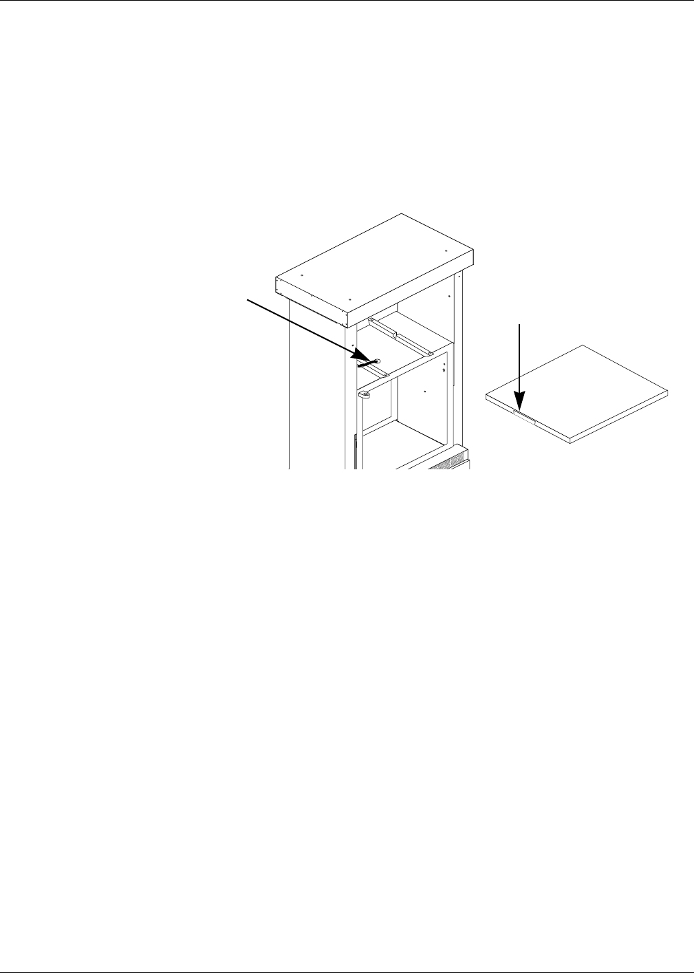
Preparing Antenna Cable Connections
Page 56 MDE-4063 TRIND TIRIS Retrofit Kit C00011-010-XXXX Installation Manual• August 2001
Preliminary
08-24-01
15 Use hacksaw to cut 3/8 inch slots in cabinet top cover to allow strip a minimum of 6" wide to
be folded back with pliers and hammered flat as shown in Figure 16, to allow cables to pass
under top cover to grommet.
Note: Remove top cover from work area to cut slot. Do not cut metal in proximity to
dispensers. Place top cover on cardboard while hammering to prevent damage to paint.
16 Clean edges and burrs around cuts in cover with file or deburring tool.
17 Thoroughly seal spaces around and between cables in main cabinet bulkhead grommet with
RTV sealant supplied with kit.
Note: Place some packaging plastic inside bulkhead grommet from top to prevent sealant
from running out bottom when applied.
18 For units with top cover end plates, replace end plate using nine screws removed and saved
with plate.
6” strip
hammered flat
under top cover
Two R20509-G2
and two
Q13578-01 cables
Figure 16:
Slotting top cover
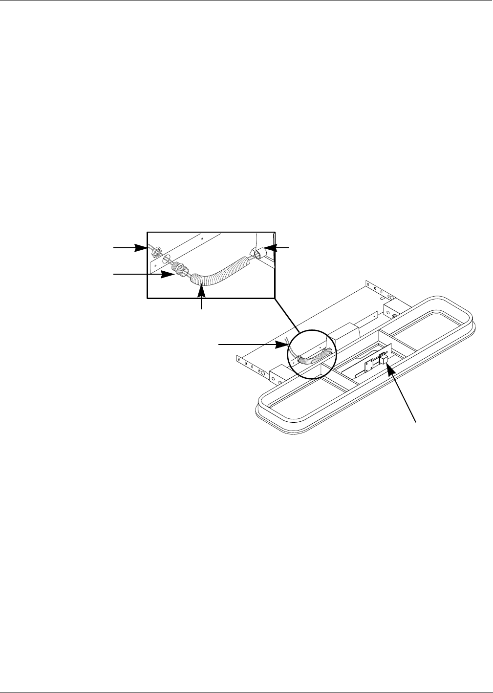
MDE-4063 TRIND TIRIS Retrofit Kit C00011-010-XXXX Installation Manual• August 2001 Page 57
Preparing Antenna Cable Connections
Preliminary
08-24-01
Installing Cables to Overhead Antennas
Cables should be separated into pairs for ‘A’ and ‘B’ side as instructed in ‘Installing
Transmitter Cables’ on page 32.
1Pull ‘A’ or ‘B’ side cables, one each R20509-G2 and Q13578-01, back through hole on
antenna bracket T20211-01 onto top of unit.
2Thread one end of plastic conduit Q13592-02 onto large threaded end of connector Q13591-01
until plastic conduit bottoms out. See Figure 17.
3 Discarding ferrule, feed pair of cables through female thread locking nut of Q13591-01
connector from non-threading side, and through hole on antenna bracket. Push other end of
plastic conduit over female thread port on connection box.
4Feed cables through Q13591-01 connector and plastic conduit into antenna connection box.
Note: Feed sufficient length of Q13578-01 cable to exit antenna connection box and reach
connector J1 on high frequency antenna.
5Push small male thread side of connector through hole in antenna bracket, and secure
connector with connector nut from other side of bracket (ferrule not needed).
Note: Be sure that flats of hex connector Q13591-01 are straight up and down on sides, or top
cover will not fit over at installation.
6If using brass connector Q13591-01, cover exposed brass with black vinyl electric tape.
7In antenna assembly connection box, connect P1 on cable R20509-G2 to J1 on low frequency
antenna board.
8Allow co-ax cable Q13578-01 to exit antenna connection box through box cover opening, and
connect P1 on co-ax cable to J1 on high frequency antenna using co-axial cable tool Q13628-
01 found in the ASC TRIND tool kit. Do not overtighten co-axial cable.
Note: Do not replace connection box cover at this time.
Figure 17: Antenna assembly and antenna cables seen from above
Plastic conduit
(Q13592-02)
One each Q13578-01
and R20509-G2 cable
‘A’ or ‘B’ side
Connector (Q13591-01)
locking nut, female thread
Connector (Q13591-01),
male thread, both ends
Female thread port on antenna
assembly connection box
High frequency antenna: J1
connection on far side - not shown
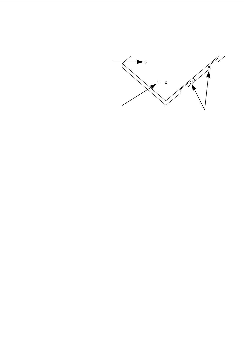
Preparing Antenna Cable Connections
Page 58 MDE-4063 TRIND TIRIS Retrofit Kit C00011-010-XXXX Installation Manual• August 2001
Preliminary
08-24-01
Installing Top Cover For units with logo display cabinet
1Remove four 3/4 inch knockouts from top cover T20213-01 for wide frames or T20215-01 for
narrow frames.
2Remove 1-1/4 inch knockout from one side of top cover for logo display wiring and use RTV
sealant to seal around underside of unused knockout.
3Reinstall locking nut first and then washer removed from lighting conduit in Step 3 of
“Removing Mobil Logo Display Cabinet” on page 21.
4Use straight edge set across bracket assembly to set nut and washer to be flush with top cover
underside when top cover is installed over bracket assembly.
Note: Installing contractor must provide as needed any additional fittings to provide
connection to logo display box in accordance with NFPA 70, The National Electric
Code.
5Place top cover on threaded rods N23880-01 holding antenna bracket assembly, being careful
not to bend top cover at weak points.
6 With top cover resting on threaded rods, feed logo display wires up through 1-1/4 inch
knockout.
7Lower top cover over threaded rods until it rests on antenna bracket assembly and wires and
rods protrude out from top cover.
8Secure top cover to mounting bracket assembly using four black sheet metal screws (K85736-
45) through two slots on each long side of top cover.
For units without logo display cabinet
1Use RTV sealant to seal around underside of unused knockouts.
2Carefully place top cover over antenna and bracket assembly.
3Secure top cover to mounting bracket assembly with four black sheet metal screws (K85736-
45) through two slots on each long side of top cover.
Four 3/4” knockouts
for mounting logo
display cabinet (two
shown)
Figure 18:
Installing top cover
Slots for screws
1-1/4” knockout
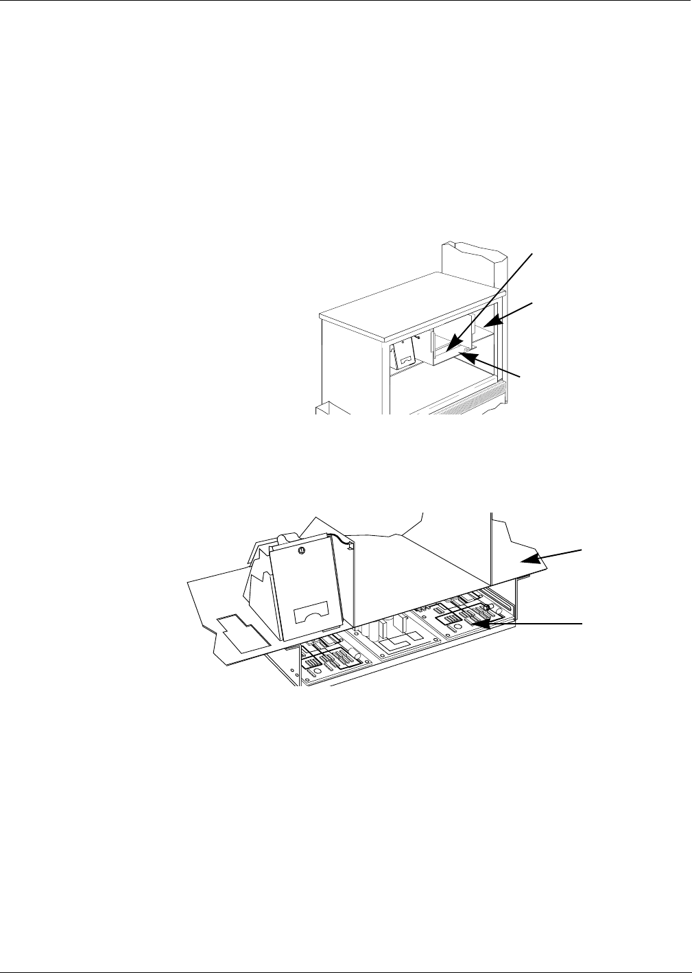
MDE-4063 TRIND TIRIS Retrofit Kit C00011-010-XXXX Installation Manual• August 2001 Page 59
Preparing Antenna Cable Connections
Preliminary
08-24-01
Routing Cables
Retrofit kit comes with twenty (20) cable clamps, four large (Q13558-06) and sixteen small
(Q13558-08). Number required for proper installation varies with units. Large clamps are for
use with power cable R20580-G1.
Note these variations for routing cable to card cage:
Horse Shoe style CRIND™
For these units, utilize opening in printer shelf bottom for routing.
Pull Out CRIND Tray
For these units utilize round 2-3/4 inch hole in printer shelf bottom, used for printer cable. Use
cable clamps to secure cables to underside of printer shelf.
Figure 19:
Horse Shoe style
CRIND Printer shelf
Horse shoe style module
Opening for cable routing
Printer shelf with
2-3/4" round hole
Pull out CRIND
electronics tray
Figure 20:
Pull Out
CRIND Tray
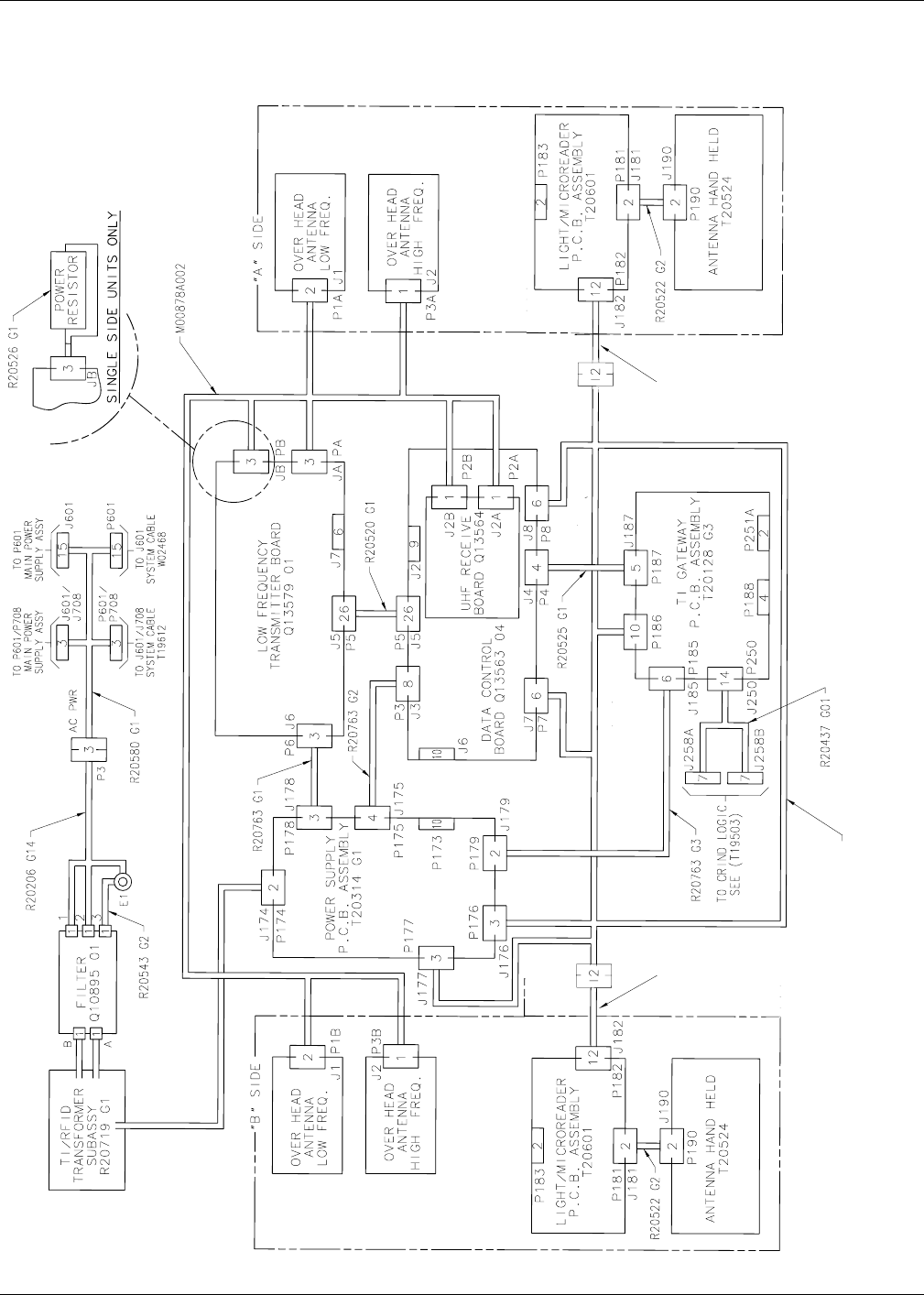
Preparing Antenna Cable Connections
Page 60 MDE-4063 TRIND TIRIS Retrofit Kit C00011-010-XXXX Installation Manual• August 2001
Preliminary
08-24-01
Cable Block Diagram R20762
T20662-G2
R20773-G2 R20773-G2
J1/J2
P2 P2
J1/J2

MDE-4063 TRIND TIRIS Retrofit Kit C00011-010-XXXX Installation Manual• August 2001 Page 61
Preparing Antenna Cable Connections
Preliminary
08-24-01
Cabinet Cable Connections
For illustration of card cage assembly, see “Card Cage Assembly T20606-G2” on page 62.
Note: For all single-sided units, install dummy load connector R20526-01 on JB on
transmitter PCB and skip all ‘B’ side connections. If power is applied to card cage
without antenna cables or dummy load connected the transmitter board will be
damaged.
Cable harness T20662-G2 is shipped with card cage connections made. Make the following
connections to the cable harness connectors:
Card Cage Connections:
Note: For illustration refer to “Card Cage Assembly T20606-G2” on page 62.
Side Connector On Installed Cable to Connector on Card Cage Harness
A J1 A Side R20773-G2 P1
B J2 B Side R20773-G2 P2
Notes: Cable R20773-G2 comes already installed in MPD-3 faceplate assembly.
Side Connector On Installed Cable to Connector on...
A PA M00878A001 JA on Card Cage
P2A J2A on Card Cage
B PB JB on Card Cage
P2B J2B on Card Cage
A&B J250 R20437-G01 P250 on Card Cage
A J258A P258A on CRIND Logic Board A Side
B J258B P258B on CRIND Logic Board B Side
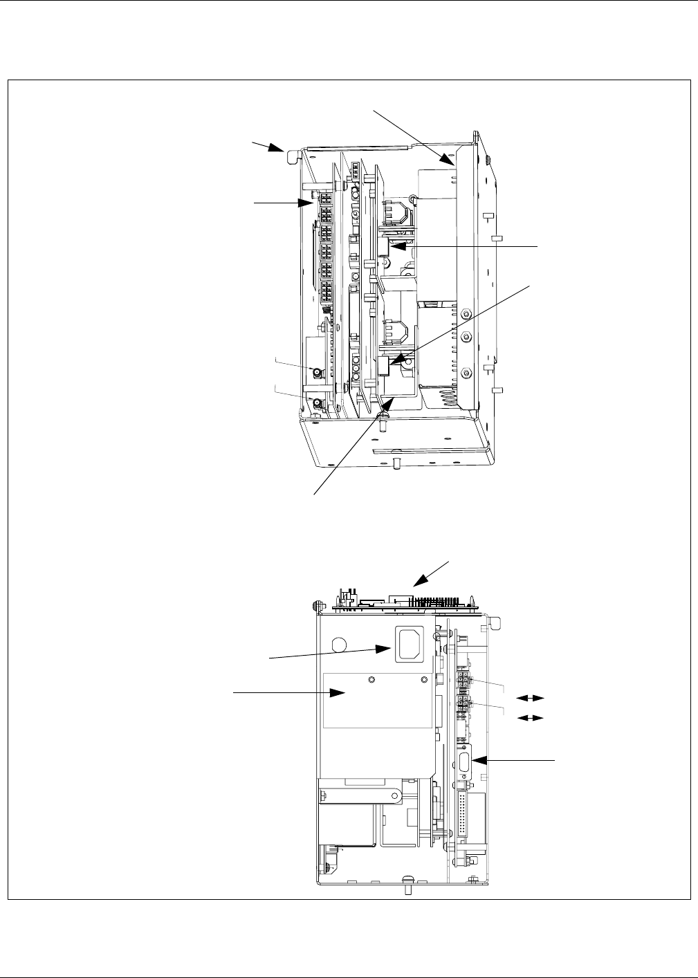
Preparing Antenna Cable Connections
Page 62 MDE-4063 TRIND TIRIS Retrofit Kit C00011-010-XXXX Installation Manual• August 2001
Preliminary
08-24-01
Card Cage Assembly T20606-G2
B
A
A
B
B
A
Transmitter (low freq) PCB
assembly Q13579-01
Data control
board
Q13563-04
Power supply (Regulator) PCB
T20314-G1
JB for ‘B’ side or
R20526-G1 dummy
load connector
JA for ‘A’ side
P250 on TIRIS Gateway PCB T20128-G3
J2A
J2B
Recessed male three
prong power receptacle
UL® label J8 for ‘B’ side
J7 for ‘A’ side
RS232 port
Back Side
Front Side
Tab for
securing to
shelf divider
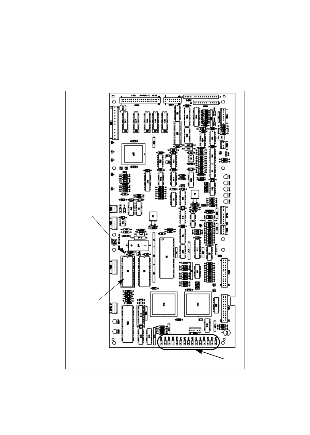
MDE-4063 TRIND TIRIS Retrofit Kit C00011-010-XXXX Installation Manual• August 2001 Page 63
CRIND® BIOS TRIND™ TIRIS Upgrade
Preliminary
08-24-01
CRIND® BIOS TRIND™ TIRIS Upgrade
Units must have current Z-180 CRIND logic board.
Install the CRIND Bios TRIND software K93744-01, one per logic board, on the T17764-XX
CRIND logic board(s) according to the following steps.
Note: A properly grounded electrostatic discharge wrist strap must be worn during this
procedure.
U7
Chip
orientation
notch
T17764-XX
CRIND
logic board
(-G3 shown)
JP1-16
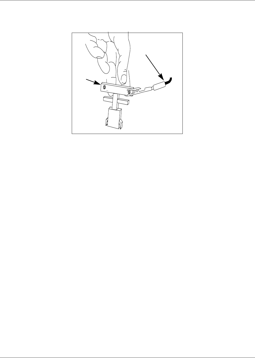
CRIND® BIOS TRIND™ TIRIS Upgrade
Page 64 MDE-4063 TRIND TIRIS Retrofit Kit C00011-010-XXXX Installation Manual• August 2001
Preliminary
08-24-01
1Locate and remove existing BIOS at U7 on CRIND logic board T17764-XX using a grounded
chip removal tool.
2Install TRIND BIOS K93744-01 (one per logic board) at position U7, orienting notch on chip
with indication mark on board as shown.
3Install jump jack on JP-16 for each side of unit.
Note: Jumper on JP-16 informs the CRIND device that a TRIND system is present.
4Restore CRIND tray to operating position.
Chip
removal
tool
Grounding strap
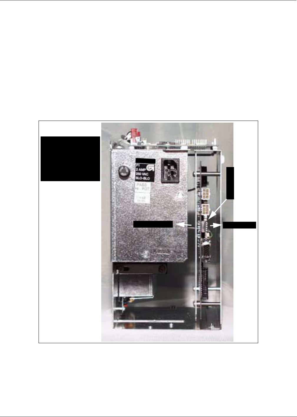
MDE-4063 TRIND TIRIS Retrofit Kit C00011-010-XXXX Installation Manual• August 2001 Page 65
Dispenser Set-Up
Preliminary
08-24-01
Dispenser Set-Up
Addressing Dispenser
Each dispenser on the G-SITE controller must be addressed differently; no two dispensers may
have the same address. Address is at discretion of the installer. Follow these steps:
1From A side of unit, locate dip switches on power supply board (PCB) T20314-G1 in card
cage.
2Using switches 2, 3, 4 and 5 address each dispenser according to the following table:
Note: Switch one in down position is stand-alone mode selected, used for service only.
Setting Baud Rate
For major oil company (MOC) TRIND installations there is no requirement to set or change
baud rate.
Switch Numbers = Value
1 = Stand-alone Mode
2 = 1
3 = 2
4 = 4
5 = 8 1
2
3
4
5
Dip switch down Dip switch up
T20606-G2
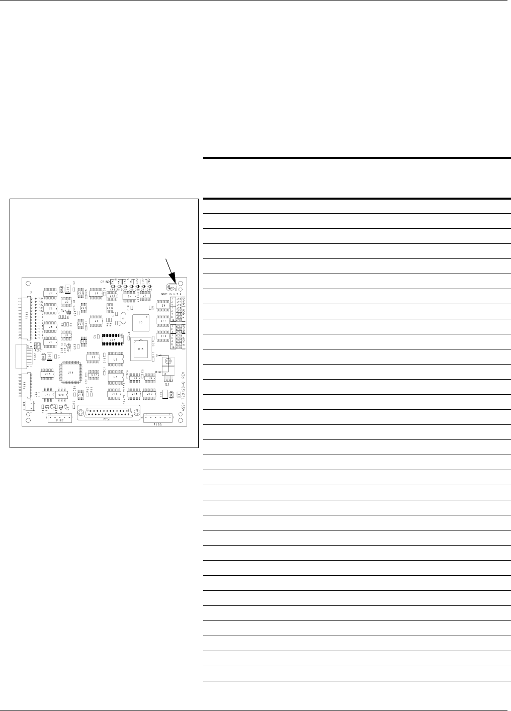
Dispenser Set-Up
Page 66 MDE-4063 TRIND TIRIS Retrofit Kit C00011-010-XXXX Installation Manual• August 2001
Preliminary
08-24-01
Addressing Gateway Board
Address for TRIND device must match address on CRIND® logic board. Follow these steps:
1Access unit’s CRIND logic board. Refer to MDE-2562 CRIND Service Manual.
2Locate jump jacks on A and B side CRIND logic boards T17764-XX.
3Note position of jump jacks and set jump jacks on Gateway board T20128-G3 to match
address on CRIND logic boards for both A and B sides.
MOC and Generic CRIND Addresses
Address On CRIND Logic Board T17764-XX JP8 JP7 JP6 JP5 JP4
= Address on Gateway Board T20128 ‘A’ Side JP1 JP2 JP4 JP8 JP16
= Address on Gateway Board T20128 ‘B’ Side JP1 JP2 JP4 JP8 JP16
1 IN OUT OUT OUT OUT
2 OUT IN OUT OUT OUT
3 ININOUTOUTOUT
4 OUT OUT IN OUT OUT
5 IN OUT IN OUT OUT
6 OUT IN IN OUT OUT
7 INININOUTOUT
8 OUT OUT OUT IN OUT
9 INOUTOUTINOUT
10 OUT IN OUT IN OUT
11 IN IN OUT IN OUT
12 OUT OUT IN IN OUT
13 INOUTININOUT
14 OUTINININOUT
15 IN IN IN IN OUT
16 OUT OUT OUT OUT IN
17 IN OUT OUT OUT IN
18 OUT IN OUT OUT IN
19 IN IN OUT OUT IN
20 OUT OUT IN OUT IN
21 IN OUT IN OUT IN
22 OUTININOUTIN
23 IN IN IN OUT IN
24 OUT OUT OUT IN IN
25 IN OUT OUT IN IN
26 OUT IN OUT IN IN
27 IN IN OUT IN IN
28 OUT OUT IN IN IN
29 INOUTINININ
30 OUTININININ
31 IN IN IN IN IN
32 OUT OUT OUT OUT OUT
Jump jack locations on Gateway Board
Accessible at upper left
hand corner of front of
card cage
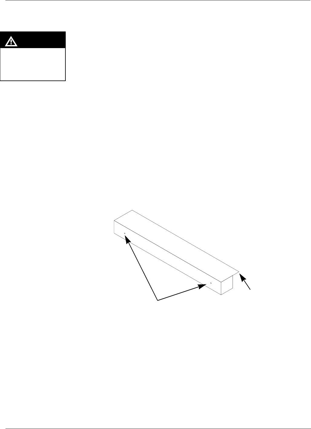
MDE-4063 TRIND TIRIS Retrofit Kit C00011-010-XXXX Installation Manual• August 2001 Page 67
Dispenser Set-Up
Preliminary
08-24-01
Installing Cladding Cap
Cladding caps R20554-01 (quantity of 2) are used to fill the gap between the side cladding and
logo display cabinet resulting from raising cabinet during the TRIND™ retrofit.
Perform the following steps to install each cladding cap.
1Replace outside sheathing with side cladding still attached, using only as many screws as
necessary to hold in place temporarily.
2Fit cladding cap R20554-01 over top of side cladding with flat piece extended on to top of logo
display cabinet. Cladding cap will extend below top edge of side cladding.
3Using center punch and hammer, mark two mounting holes (per unit side) on side cladding
through two existing holes in cladding cap.
4Remove outside sheathing and attached side cladding from unit, and take to a non-hazardous
location away from the fuel island.
5Drill holes at the points marked by the center punch for self-threading screws K85736-45.
6Re-install the outside sheathing with side cladding attached using all screws removed during
disassembly.
7Attach cladding cap to side cladding using K85736-45 self threading black screws.
8Proceed to “CRIND® BIOS TRIND™ TIRIS Upgrade” on page 63.
CAUTION
If power tools are used for
assembly work must be
done at least 20" from fuel
island
Figure 20: Installing cladding cap
Pre-drilled holes for mounting
cladding cap to top of outside
sheathing with K85736-45
screws
Flat extension sits on
top of logo display
cabinet
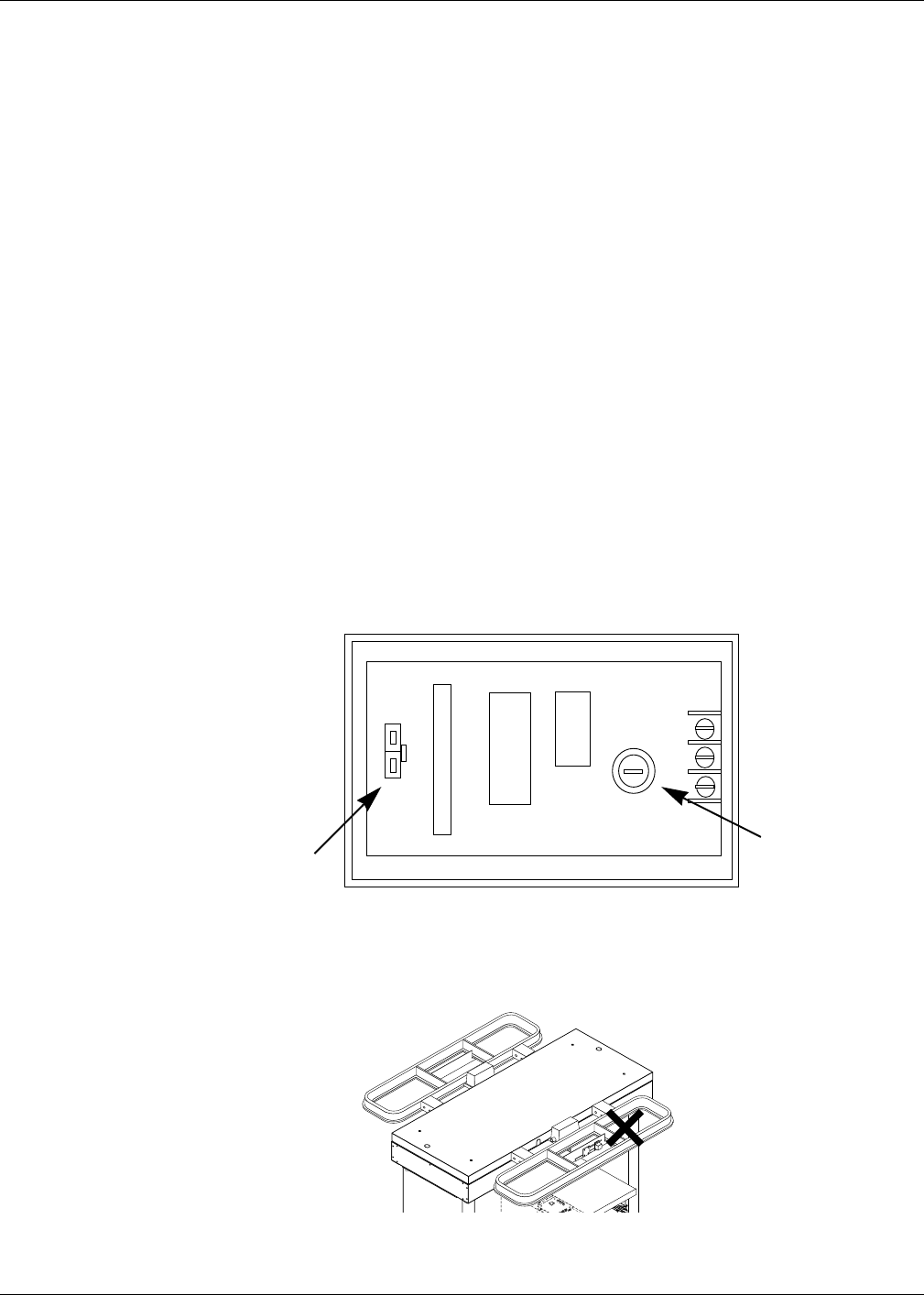
Dispenser Set-Up
Page 68 MDE-4063 TRIND TIRIS Retrofit Kit C00011-010-XXXX Installation Manual• August 2001
Preliminary
08-24-01
Preparation for Tuning Antennas
Antenna tuning requires use of field strength sensor Q13626-01 supplied with ASC tool kit.
1For units without G-Site™ put unit in ‘Stand Alone’ mode by disconnecting J4 on the DCB
board and placing jumper on light microreader board at JP3.
Note: JP3 and J4 can never both be in or both out. One and only one must always be in, the
other out.
2Restore power to unit(s) and cold start the CRIND. Refer to MDE-2562, CRIND Service
Manual for detailed instructions.
Note: Be sure transmitter cables are connected before restoring power.
3Once the CRIND display indicates unit is downloading, remove the Cold Start jump jack.
Tuning Antennas
1Locate tuning pot on printed circuit board in over-head antenna connection box. Pot has slot
for tuning tool. See Figure 20.
2Tuning pot in ‘A’ side over head antenna connection box should be turned out 5 to 6 turns.
Note: Use tuning tool Q13631-01 from the ASC TRIND tool kit to make pot adjustments.
Refer to MDE-3640 ASC TRIND Tool Kit for instructions.
3Place field strength sensor in position shown on ‘A’ side plastic antenna housing, to right of
connection box and on top of plastic antenna housing. See Figure 22.
Figure 21:
Tuning pot location
in overhead
antenna connection
box
Tuning pot - use
tuning tool to
adjust
J1
Figure 22:
Position field
strength sensor
Q13626-01
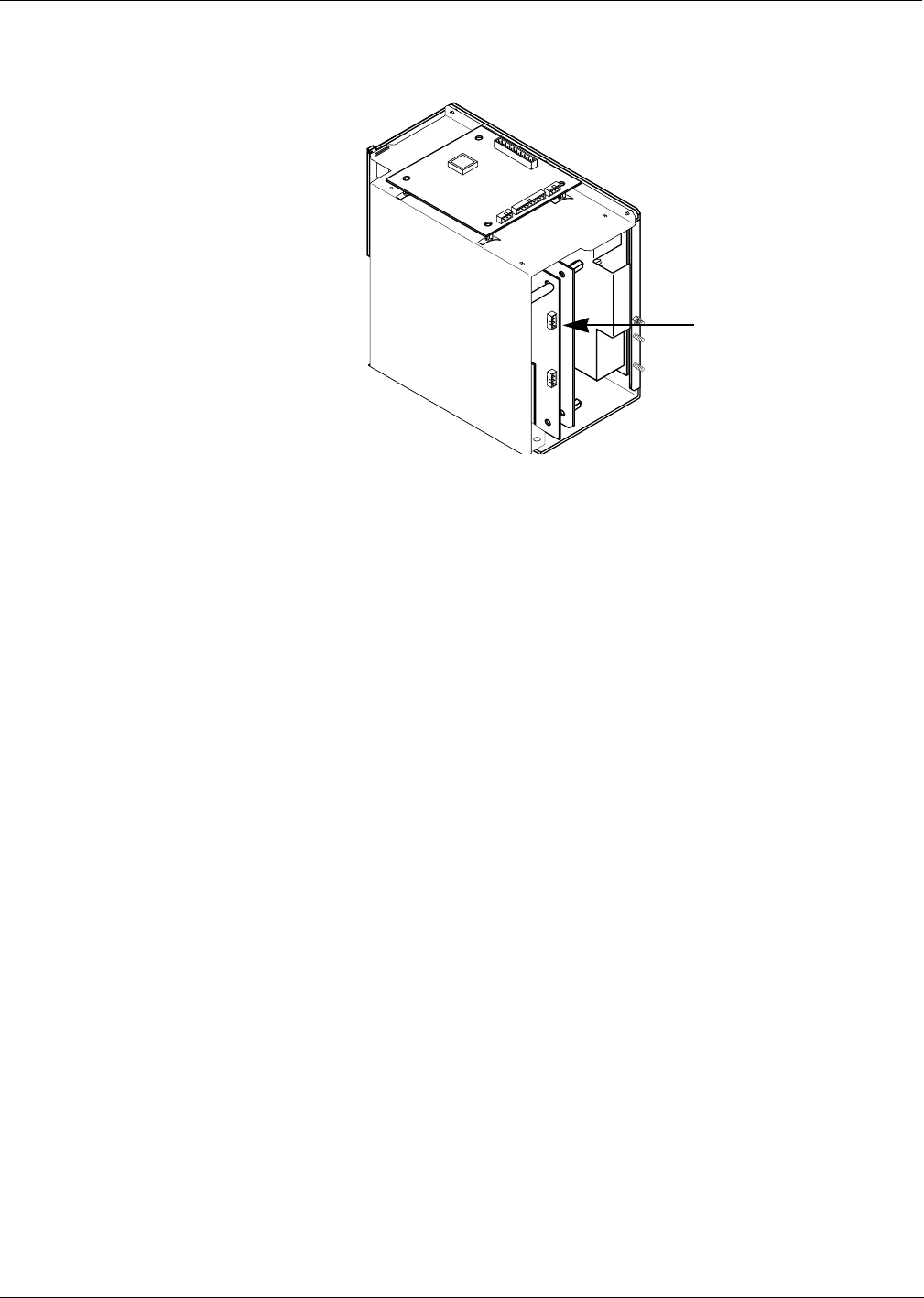
MDE-4063 TRIND TIRIS Retrofit Kit C00011-010-XXXX Installation Manual• August 2001 Page 69
Dispenser Set-Up
Preliminary
08-24-01
4On card cage, move three position ‘tune’ toggle switch from center position to ‘A’. See Figure
23.
5Connect leads on multi-meter set to DC voltage to field strength sensor.
6By fine adjustments to tuning pot, set to highest DC voltage reading.
Note: Voltage will peak at a point, and then decrease with turns in either direction. Set at
peak.
7On antenna connection box top cover, cut cover gasket over groove cut in cover.
8Reinstall cover with screws supplied allowing antenna cable Q13578-01 to pass out of box
through groove.
9Repeat Steps 1 through 8 for ‘B’ side and then return tune toggle switch to center position.
‘Tune’ toggle switch location
Figure 23:
Tune toggle
switch

Dispenser Set-Up
Page 70 MDE-4063 TRIND TIRIS Retrofit Kit C00011-010-XXXX Installation Manual• August 2001
Preliminary
08-24-01
Testing TRIND
Perform the following procedures to test the TRIND.
1Place the unit in the stand alone mode or ensure that the unit is operating with a G-SITE.
2From ‘A’ side of unit touch hand held test tag (Q13630-02 from the ACS TRIND tool kit) to
TRIND target graphic. Door or faceplate TRIND indicator will light.
Note: If indicator fails to light check whether light on other side is on; if so it indicates a
crossing of ‘A’ and ‘B’ side cables. Check connections.
3From ‘A’ side of unit hold car mount test tag (Q13630-01 from the ASC TRIND tool kit) in
front of unit, at a distance of approximately 6 feet from overhead antenna. Door or faceplate
TRIND indicator will light.
4Repeat Steps 1 through 3 for ‘B’ side.
Alternative Testing Using Laptop
1Connect laptop to RS232 port on DCB.
2Go to:
•Windows program
•Accessories
•Terminal
•Settings
•Communications
3Set for:
•9600 baud
•8 bit
•No parity
•Comm 1
4Then go to:
•Help screen
•Antenna scan
•Choose 1, 2, 3 and 4
Note: This will test both antennas
5From ‘A’ side of unit touch hand held test tag (Q13630-02 from the ACS TRIND tool kit) to
front of TRIND target graphic. Door or faceplate TRIND indicator will light.
6From ‘A’ side of unit hold car mount test tag (Q13630-01 from the ASC TRIND tool kit) in
front of unit, at a distance of approximately 6 feet from overhead antenna. Door or faceplate
TRIND indicator will light.
7Repeat Steps 5 and 6 for ‘B’ side.

MDE-4063 TRIND TIRIS Retrofit Kit C00011-010-XXXX Installation Manual• August 2001 Page 71
Dispenser Set-Up
Preliminary
08-24-01
Re-installing Logo Display Cabinet
Note: Logo display cabinet weighs approximately 75 lbs. Two people are required to perform
steps 1 through 3.
1Carefully lift and place logo display cabinet on top of unit so that it rests on the four threaded
rods N23880-01.
2With logo display cabinet carefully held in place, feed lighting wires on top cover up into
cabinet.
3With wires fed into cabinet, carefully lower cabinet over threaded rods and conduit nipple until
cabinet rests securely on top cover, taking care that wires are not crushed by cabinet.
4Remove two threaded rods from opposite corners.
5Secure logo display cabinet to unit top using two of four Q12617-04 bolts, 3" long, and lock
washers, flat washers and soft aluminum washers removed in Step 5 of ‘Removing Mobil
Logo Display Cabinet’ on page 22, through two mounting holes without threaded rods.
6With logo display secured, remove remaining two threaded rods and replace with remaining
two Q12617-04 bolts, soft aluminum washers, flat washers and lock washers. Keep threaded
rods for other installations.
Note: Return threaded rods N23880-01 to the ASC TRIND tool kit to be used for future
installations.
7Install washer first and then locking nut on to conduit nipple extending into logo display
cabinet, and tighten.
Note: Install contractor supplied fittings (washers, locking nuts, conduit connectors, etc.) as
needed on conduit nipple to provide electrical connection to logo display box in
accordance with NFPA 70, The National Electric Code. Washers and locking rings
must firmly secure metal to metal surfaces of top cover and logo display cabinet at
conduit.
8From inside of logo display cabinet seal four unused slots (1/2 inch x 5/8 inch) with RTV.
(Slots were for cladding to display cabinet fasteners.)
9Reconnect wires disconnected in Step 2 of ‘Removing Mobil Logo Display Cabinet’ on
page 21.
10 Reinstall logo display faceplates, re-using the six screws per side removed in Step 1 of
‘Removing Mobil Logo Display Cabinet’ on page 21.
Q12616-04 bolt (3")
Lock washer
Flat washer
Soft aluminum washer
Figure 24: Logo display cabinet hardware

Dispenser Set-Up
© 2001 Marconi Commerce Systems Inc.
7300 West Friendly Avenue • Post Office Box 22087
Greensboro, North Carolina 27420
Phone (336) 547-5000 • http://www.marconicommerce.com • Printed in the U.S.A.
MDE-4063 TRIND TIRIS Retrofit Kit C00011-010-XXXX Installation Manual• August 2001
Preliminary
08-24-01
Completing Installation
After all testing has been completed, do the following:
1Shut off all power to the unit.
2Replace or refasten all components and hardware, including:
•Replace all sheathing and/or pans removed.
3Close all secure all doors.
4Clean up work site, removing all materials to be discarded and all tools.
5Reapply power and Cold Start the unit.
CRIND® is a registered trademark of Marconi Commerce Systems.
Exxon® is a registered tradmark of the Exxon Corporation.
Mobil® is a registered trademark of the Mobil Oil Company.
MPD®-3 Multi-product Dispenser is a registered trademark of Marconi Commerce Systems.
TRIND® is a registered trademark of Marconi Commerce Systems
UL® is a registered trademark of Underwriters’ Laboratories.