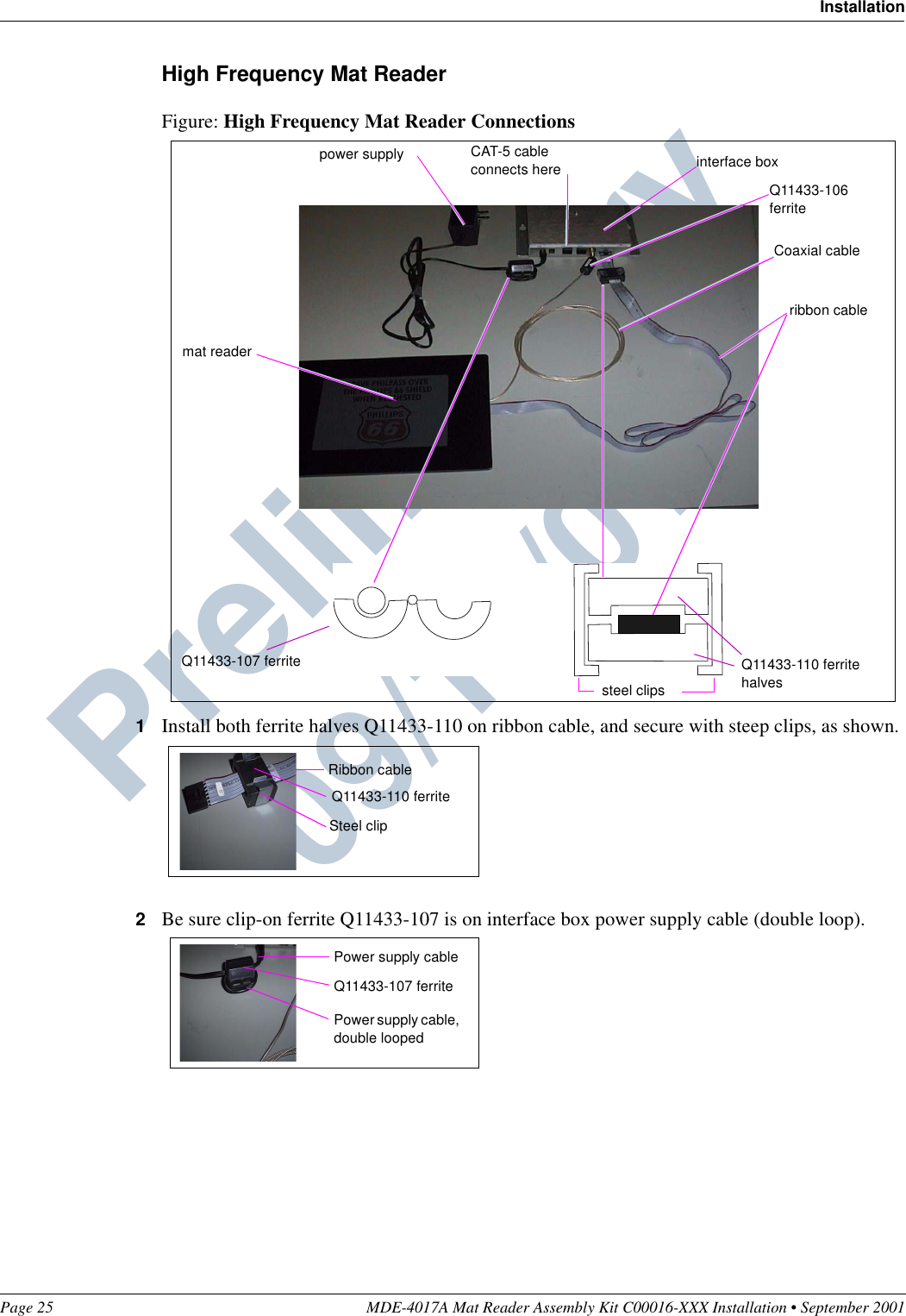
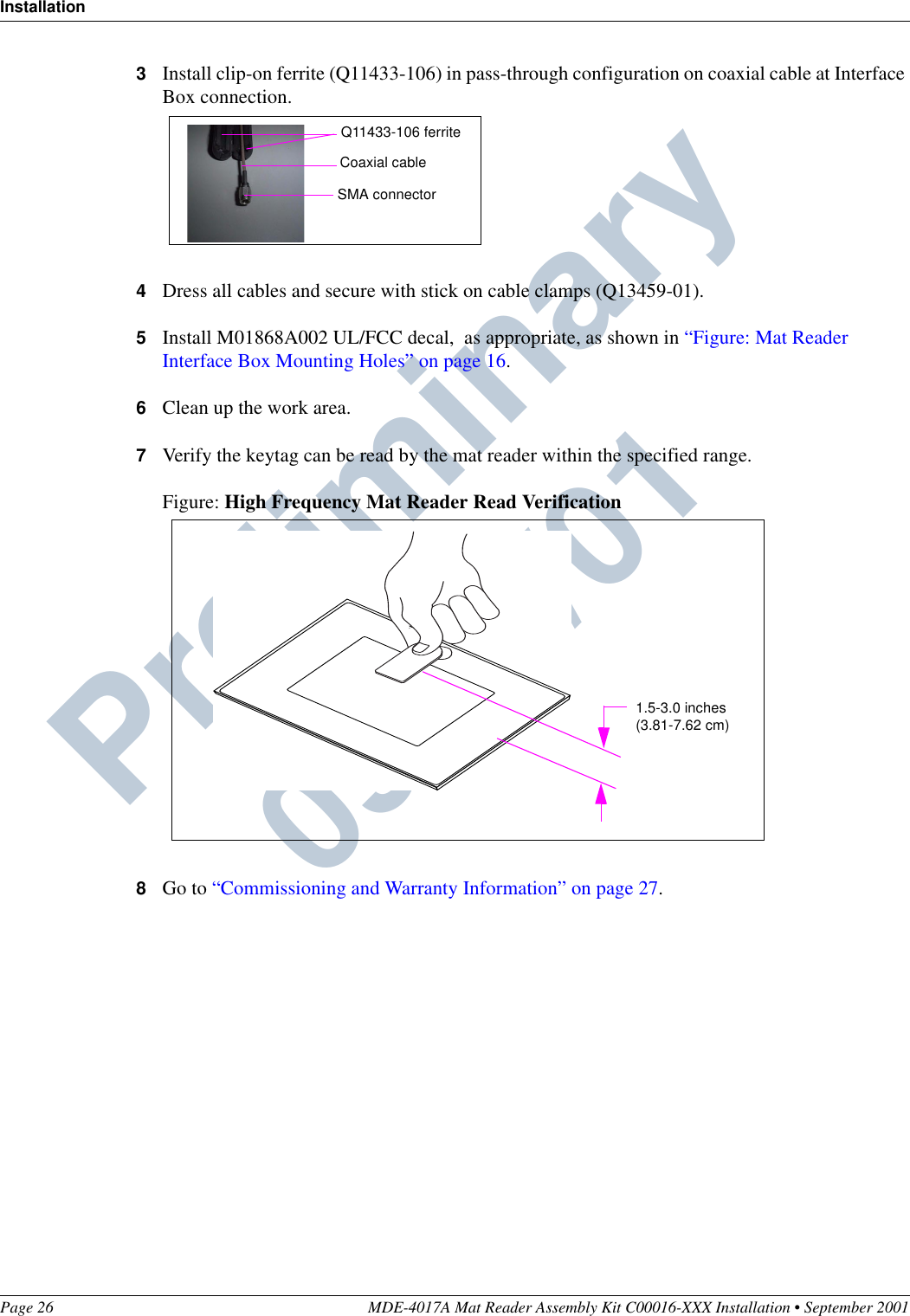
Gilbarco MRIR12 MAT Reader Assembly User Manual Mat Reader Assembly Kit C00016 XXX Installation

Gilbarco Inc. MAT Reader Assembly Mat Reader Assembly Kit C00016 XXX Installation

Manual

MDE-4017A Mat Reader Assembly Kit C00016-XXX Installation • September 2001 Page 1Preliminary  09/13/01IntroductionPurpose of this ManualThis manual provides instruction for installing Mat Reader Assembly Kit C00016-XXX.The Mat Reader allows customers to automatically authorize sales using a hand-held transponder tag.Important NoticeThis equipment has been tested and found to comply with the limits for a Class A digital device pursuant to Part 15 of the Federal Communications Commission (FCC) Rules. These limits are designed to provide reasonable protection against harmful interference when the equipment is operated in a commercial environment. This equipment generates, uses and can radiate radio frequency energy, and if not installed and used in accordance with the instruction manual, may cause harmful interference to radio communications. Operation of this equipment in a residential area is likely to cause harmful interference in which case the user will be required to correct the interference at his own expense. Changes or modifications not expressly approved by the manufacturer could void the user’s authority to operate this equipment.The long term characteristics or the possible physiological effects of radio frequency electromagnetic fields have not been investigated by Underwriters’ Laboratories, Inc. (UL®).Required ReadingBefore installing the equipment, the installer must read, understand, and follow:•this manual•NFPA 70, The National Electric Code•applicable federal, state and local codes and regulationsFailure to do so may adversely effect the safe use and operation of the equipment.MDE-4017AMat Reader Assembly Kit C00016-XXXInstallationSeptember 2001
Important Safety InformationPage 2 MDE-4017A Mat Reader Assembly Kit C00016-XXX Installation • September 2001Preliminary  09/13/01Important Safety InformationThis section introduces the hazards and safety precautions associated with installing, inspecting, maintaining or servicing this product. Before performing any task on this product, read this safety information and the applicable sections in this manual, where additional hazards and safety precautions for your task will be found. Electrical shock could occur and cause death or serious injury if these safe service procedures are not followed.Preliminary PrecautionsRead, understand and follow this manual and any other labels or related materials supplied with this equipment.Follow the RegulationsThere is applicable information in: NFPA 70: National Electrical Code (NEC); OSHA regulations; and federal, state, and local codes which must be followed. Failure to install, maintain or service this equipment in accordance with these codes, regulations and standards may lead to legal citations with penalties or affect the safe use and operation of the equipment.
Page 3 MDE-4017A Mat Reader Assembly Kit C00016-XXX Installation • September 2001Important Safety InformationPreliminary  09/13/01Safety Symbols and Warning WordsAlert Symbol This safety alert symbol is used in this manual and on warning labels to alert you to a precaution which must be followed to prevent potential personal safety hazards. Obey safety directives that follow this symbol to avoid possible injury or death.Signal WordsThese signal words used in this manual and on warning labels tell you the seriousness of particular safety hazards. The precautions that follow must be followed to prevent death, injury or damage to the equipment.Proper Grounding is RequiredProper grounding is required for safe operation. See installation manual and applicable NEC, NFPA and local electrical codes for requirements.Avoid Pinched WiresPinched or cut wires (cables) may damage components. Exposed wires could create sparks and electrical shorts when applying power.Other Useful Safety InformationReplacement PartsUse only genuine Marconi replacement parts. Using parts other than genuine Marconi replacement parts could create a safety hazard, violate national, state and local regulations or void warranty.This signal word designates a hazard or unsafe practice which may result in minor injury.This signal word is used to alert you to a hazard or unsafe practice which will result in death or serious injury.This alerts you to a hazard or unsafe practice that could result in death or serious injury.CAUTIONWhen used by itself, CAUTION designates a hazard or unsafe practice which may result in property or equipment damage.CAUTIONDANGERWARNING
Reference InformationPage 4 MDE-4017A Mat Reader Assembly Kit C00016-XXX Installation • September 2001Preliminary  09/13/01Reference InformationRelated DocumentsInstaller must obtain, read and understand all site preparation documentation provided by the point of sale company authorizing the installation before attempting to install this equipment.In addition, the installer must be familiar with the information in the following documents:Required ToolsThe following equipment is needed to install all Mat Reader kits:•drill motor and bits•needle nose pliers•screwdriver, Phillips® head•Zircon® stud/bracket finderCoaxial Cable and SMA Connector Handling RequirementsCoaxial antenna cables are more flexible and have a smaller diameter than more familiar coaxial cable, such as that used for cable television. However, all coaxial cables share this characteristic: turns or bends in coaxial cables must be gradual loops, no sharper than a 1-inch radius or 2-inch diameter (2.54 centimeter radius or 5 centimeter diameter).An SMA connector is a type of connector that uses a threaded mount and connects one optical fiber. Due to its small size, use care when connecting the coaxial cable to as to not damage the SMA connector on the Interface Box or the coaxial cable.Document Number Title GOLDSM LibraryMDE-3110 PC-Based G-SITE® System Installation Manual G-SITEMDE-3111 PC-Based G-SITE System Start-Up and Service Manual • G-SITE•Service ManualMDE-3620 Gilbarco® POS Console Site Preparation Manual Site PrepMDE-3982 Advanced Console Application KS000-XXXPC G-SITEToo severe a turn or bend in the cable will break the center (solid) fiber. This can result in an intermittent signal. It may also result in what appears to be proper performance at installation that is followed by premature failure and field service.In addition, a damaged cable will cause a situation where the transmitter printed circuit board (PCB) is powered without load, and damage the printed circuit board. CAUTION
Page 5 MDE-4017A Mat Reader Assembly Kit C00016-XXX Installation • September 2001Parts ListsPreliminary  09/13/01Parts ListsC00016-006 Kit - Low FrequencyC00016-006 Kits contain the following parts:C00016-008 Kit - High FrequencyC00016-008 Kits contain the following parts:Description Part Number Quantitybox, interface assembly M01814A001 1tape, neoprene foam M01870B001 2channel, plastic filler M01871B001 1cable, mat reader drive M01872A001 1ferrite half Q11433-110 2ferrite, snap-on Q11433-107 1tape, acrylic foam K85492-72 1power supply M01878B001 1jack, jump Q11011-01 1cable, data, CAT-5 Q13482-06 1clamp, cable, stick on, small Q13459-01 3decal, UL/FCC M01868A001 1document, installation MDE-4017 1screw, thread forming, 8-32x3/8”K85736-06 2Description Part Number Quantitybox, interface assembly M01814A002 1tape, neoprene foam M01870B002 1channel, plastic filler M01871B002 1cable, mat reader drive M01872A001 1transient suppressor, magnetically coupled Q11433-110 2ferrite, snap-on Q11433-106 1ferrite, snap-on Q11433-107 1tape, acrylic foam K85492-72 1power supply M01878B001 1jack, jump Q11011-01 10cable, data, CAT-5 Q13482-06 1clamp, cable, stick on, small Q13459-01 3decal, UL/FCC M01868A002 1document, installation MDE-4017 1screw, thread forming, 8-32x3/8”K85736-06 2
Parts ListsPage 6 MDE-4017A Mat Reader Assembly Kit C00016-XXX Installation • September 2001Preliminary  09/13/01Mat ReaderThe following component is also required in addition to the C00016-XXX kit.Description Part Number Quantitymat reader MR01002GXXX 1Note: XXX is the graphic-specific identifier.
Page 7 MDE-4017A Mat Reader Assembly Kit C00016-XXX Installation • September 2001Interconnect/Block DiagramsPreliminary  09/13/01Interconnect/Block DiagramsMat Reader Interconnect/Block Diagram M01873In Mat Reader AssemblyMR01002GXXXIn Interface Box  AssemblyM01814A001115VACDC+12VDC
Interconnect/Block DiagramsPage 8 MDE-4017A Mat Reader Assembly Kit C00016-XXX Installation • September 2001Preliminary  09/13/01Mat Reader Interconnect/Block Diagram M02110NOTE: FOR DAISYCHAINING, FOLLOWINSTRUCTIONS IN THE “ADDRESSINGLOGIC BOARD - ONLY FOR DAISYCHAINING”SECTION OF MDE-4017.
Page 9 MDE-4017A Mat Reader Assembly Kit C00016-XXX Installation • September 2001InstallationPreliminary  09/13/01InstallationNote: All installation work is to be accomplished between the hours specified by the point of sale company authorizing the installation.Install the Mat Reader assembly according to the following instructions.Collect and arrange for safety and convenience all tools and equipment.Positioning the Mat ReaderMarconi recommends the following concerning the placement of a Mat Reader on the counter top relative the following devices:•any cathode ray tube (CRT), such as the point-of-sale (POS) monitor•any device with a card reader, such as a personal identification number (PIN) pad•the Mat Reader Interface Box•countertop materialIn Relation to a CRTIn general, a Mat Reader should be positioned as far away as is conveniently possible from any CRT device to avoid interference from the CRT and to ensure optimum performance of the Mat Reader. The interference from a CRT can vary greatly from unit to unit and model to model. Also, the presence of nearby masses of metal can affect the influence of a CRT. There is no universal minimum separation that guarantees trouble-free operation. If the distance between the Mat Reader and CRT cannot be increased, changing the relative orientation of these items may yield better operation of the Mat Reader. However, increasing the distance will always give the most dramatic improvement in Mat Reader performance.In Relation to a Card ReaderIn general, any device with a card reader should be positioned as far as is conveniently possible from a Mat Reader. Since card readers are unshielded, loosely filtered devices, they are potential victims of any magnetic interference. The Mat Reader generates a magnetic field as part of its normal operation that can be such a source of magnetic interference to a card reader.If a known, good card reader begins to display poor read performance after the addition of a Mat Reader to the POS system, significant improvements to card reader performance may be realized by simply increasing its separation from the Mat Reader by as little as a few inches. As a general rule, placing a card reader beside a Mat Reader has far less effect on the card reader than actually using the card reader while it is physically on, or held over, the Mat Reader. A counter top configuration where the card reader could be used in this manner should be avoided.
InstallationPage 10 MDE-4017A Mat Reader Assembly Kit C00016-XXX Installation • September 2001Preliminary  09/13/01In Relation to the Interface BoxFor optimum Mat Reader performance, the Interface Box should be positioned as close to the Mat Reader as is conveniently possible. If necessary, the CAT-5 cable, Q13482-06, may be swapped out for a longer version in order to properly place the Interface Box and still reach the POS connection. The dash number, such as -06, indicates 6 feet (1.8 meters) long.In Relation to the Countertop MaterialIf the countertop material is stainless steel, Formica® covered steel, or some other metallic material, less than desired performance will be experienced. In the preferred setup, the countertop should be Corian®, plastic, wood, or some other non-metallic and/or non-ferrous material.
Page 11 MDE-4017A Mat Reader Assembly Kit C00016-XXX Installation • September 2001InstallationPreliminary  09/13/01Setting Baud Rate1Remove Mat Reader Interface Box cover to access the logic board.Figure: M01814A001 Mat Reader Interface Box CoverFigure: M01814A002 Mat Reader Interface Box Covercover screwcoverlogic boardcover screwcoverlogic board
InstallationPage 12 MDE-4017A Mat Reader Assembly Kit C00016-XXX Installation • September 2001Preliminary  09/13/012Locate jump jacks on logic board for Mat Reader.Figure: Jump Jacks for Baud Rate Setting - M01803A001Figure: Jump Jacks for Baud Rate Setting - M01803A002
Page 13 MDE-4017A Mat Reader Assembly Kit C00016-XXX Installation • September 2001InstallationPreliminary  09/13/013Set the jump jacks as follows (see the appropriate figure: “Figure: Jump Jacks for Baud Rate Setting - M01803A001” on page 12 or “Figure: Jump Jacks for Baud Rate Setting - M01803A002” on page 12).4If not daisychaining Mat Reader Interface Boxes, reinstall cover.Note: Daisychaining is connecting the output from one Interface Box to the input of another.Mat Reader Baud RatesBaud Rate (Note) BAUD 1 BAUD 2 BAUD 44800 OUT OUT OUT2400 IN OUT OUT1200 OUT IN OUT300 IN IN OUT38400 OUT OUT IN19200 IN OUT IN9600 OUT IN IN4800 IN IN INNote: 4800 is the default value and the Mat Reader value.Electrostatic Discharge DamageWorking on electronics without connecting to a ground or dischargingstatic can damage electronic parts. Use a wrist strap.  CAUTION
InstallationPage 14 MDE-4017A Mat Reader Assembly Kit C00016-XXX Installation • September 2001Preliminary  09/13/01Addressing Logic Board - Only for DaisychainingAddress for Mat Reader must match address on previously installed Mat Reader. Follow these steps:1Access logic board for Mat Reader being installed.2Locate jump jacks on previously installed Mat Reader logic board M01803A001 or M01803A002 as appropriate.Figure: M01803A001 Jump Jacks for Address SettingFigure: M01803A002 Jump Jacks for Address Setting
Page 15 MDE-4017A Mat Reader Assembly Kit C00016-XXX Installation • September 2001InstallationPreliminary  09/13/013Note position of jump jacks on previously installed Mat Reader logic board, and set jump jacks on board for Mat Reader being installed to match address on logic board.4Reinstall cover.Mat Reader AddressesAddress on Logic Board M01803A001/M01803A002 ADDR 1 ADDR 2 ADDR 4 ADDR 8 ADDR 160 OUT OUT OUT OUT OUT1 IN OUT OUT OUT OUT2 OUT IN OUT OUT OUT3 ININOUTOUTOUT4 OUT OUT IN OUT OUT5 IN OUT IN OUT OUT6 OUT IN IN OUT OUT7 INININOUTOUT8 OUT OUT OUT IN OUT9 IN OUT OUT IN OUT10 OUT IN OUT IN OUT11 IN IN OUT IN OUT12 OUT OUT IN IN OUT13 IN OUT IN IN OUT14 OUTINININOUT15 IN IN IN IN OUT16 OUT OUT OUT OUT IN17 IN OUT OUT OUT IN18 OUT IN OUT OUT IN19 IN IN OUT OUT IN20 OUT OUT IN OUT IN21 IN OUT IN OUT IN22 OUTININOUTIN23 IN IN IN OUT IN24 OUT OUT OUT IN IN25 IN OUT OUT IN IN26 OUT IN OUT IN IN27 IN IN OUT IN IN28 OUT OUT IN IN IN29 IN OUT IN IN IN30 OUTININININ31 IN IN IN IN INElectrostatic Discharge DamageWorking on electronics without connecting to a ground or dischargingstatic can damage electronic parts. Use a wrist strap.  CAUTION
InstallationPage 16 MDE-4017A Mat Reader Assembly Kit C00016-XXX Installation • September 2001Preliminary  09/13/01Mounting Mat Reader Interface Box1Determine the location for the installation of indoor equipment. The Interface Box may be mounted under the counter top (upside down) or vertically on one of the supporting walls of the counter top.Note: Refer to site prep document provided by point of sale company and keep in mind overall 5-foot (1.5 meter) length of cable to connect Mat Reader Interface Box to Mat Reader. Also refer to “In Relation to the Interface Box” on page 10.2Use a Zircon stud/bracket finder to ensure no electrical conduits or pipes are located inside of wall where the Mat Reader Interface Box is to be mounted. Also, ensure the Mat Reader Interface Box is to be located where studs or wall (concrete/brick/drywall) mollys can be used for mounting.3Mark and drill holes. Insert wall mollys if required.4Use 8-32 thread-forming screws provided or other appropriate contractor-supplied mounting hardware to secure the Mat Reader Interface Box to the wall or under counter top.Note: 3/8-inch deep pilot holes (approximately 1/8-inch diameter) will be required if the screws provided are used.Figure: Mat Reader Interface Box Mounting HolesDo not use the Mat Reader Interface Box as a drill guide. It may be used as a template to mark the holes to be drilled.CAUTIONmounting holes
Page 17 MDE-4017A Mat Reader Assembly Kit C00016-XXX Installation • September 2001InstallationPreliminary  09/13/01Connecting Data Cables to Mat Reader Interface BoxRun both power and data cables to port end of Mat Reader Interface Box (see “Figure: Mat Reader Interface Box Mounting Holes” on page 16) as follows:1Connect the P3 end of the ribbon cable (M01872A001) to the interface port (P3).2Connect the J1 end of the CAT-5 cable (Q13482-06) to the J1IN port.Note: The other end of the CAT-5 cable will be connected to the POS controller in the instructions for “Connecting Data Cables from the Mat Reader Interface Box” on page 18.3If daisychaining Interface Boxes, connect a CAT-5 cable from the J1IN port on the other Interface Box to the J2OUT port on this Interface Box.4If the Interface Box has an antenna connection, connect one end of the coaxial cable to the antenna connection (“Figure: Connecting to Mat Reader Interface Box M01803A002” on page 17). See “Coaxial Cable and SMA Connector Handling Requirements” on page 4.Figure: Connecting to Mat Reader Interface Box M01803A001Figure: Connecting to Mat Reader Interface Box M01803A002Connect power supply here.Connect J1 end of CAT-5 cable here.If daisychaining, connect CAT-5 from J1IN on other interface box here.Connect P3 end of ribbon cable here.Connect power supply here. Connect J1 end of CAT-5 cable here.If daisychaining, connect CAT-5 from J1IN on other interface box here.Connect P3 end of ribbon cable here.Connect SMA connector on coaxial cable to antenna connection.
InstallationPage 18 MDE-4017A Mat Reader Assembly Kit C00016-XXX Installation • September 2001Preliminary  09/13/01Connecting Data Cables from the Mat Reader Interface BoxLow Frequency Mat Reader1Position Mat Reader face down.Figure: Bottom Side of Mat Reader - Low Frequency2Select side for ribbon cable (M01872A001) connection based on counter top configuration requirements.Note: The Mat Reader is designed to be placed on a counter top beside or adjacent to a cash register or point-of-sale (POS) terminal. If properly positioned, the Mat Reader ribbon cable will “disappear” underneath the existing POS equipment. The ribbon cable will penetrate the counter top via the same hole used by the POS power and data cables. Double-sided tape (not provided) may be used to secure the Mat Reader and/or the ribbon cable in position on the counter top.3Install strip of acrylic foam tape (K85492-72) in base of channel on side selected for ribbon cable.4Peel second release liner, exposing adhesive.5Carefully connect the P1/P2 end of the ribbon cable (M01872A001) to the back side of the Mat Reader.Note: The cable can be plugged in from either side; the orientation does not matter. Be sure the cable will be flat and not twisted once the Mat Reader is face up.bottom side of Mat Reader7-pin cable connectorchannel for ribbon cable neoprene foam tapeacrylic foam taperibbon cable7-pin Mat Reader connectors (only one used)plastic channel filler
Page 19 MDE-4017A Mat Reader Assembly Kit C00016-XXX Installation • September 2001InstallationPreliminary  09/13/01Figure: Connecting to Mat Reader - Low Frequency6Peel release liner and install neoprene foam tape (M01870B001) over ribbon cable and sides of channel. Foam tape should fit snugly into cutout of surrounding foam tape backer.7On unused cable channel, install plastic filler channel (M01871B001).8Install remaining neoprene foam tape (M01870B001) over filler channel. Foam tape should fit snugly into cutout of surrounding foam tape backer.9Gently turn the Mat Reader to the face-up position.Figure: Mat Reader - Face Up10 Connect the loose end of the CAT-5 cable to the POS system.Note: For a G-SITE system, the exact G-SITE system port depends on the G-SITE system configuration. Refer to MDE-3110 PC-Based G-SITE System Installation Manual.7-pin cable connectorchannel for ribbon cable neoprene foam tapeacrylic foam taperibbon cableplastic channel fillerunused channel neoprene foam tapecarefully connect these
InstallationPage 20 MDE-4017A Mat Reader Assembly Kit C00016-XXX Installation • September 2001Preliminary  09/13/01High Frequency Mat Reader1Position Mat Reader face down.Figure: Bottom Side of Mat Reader - High Frequency2Select side for ribbon cable (M01872A001) connection based on counter top configuration requirements.Note: The Mat Reader is designed to be placed on a counter top beside or adjacent to a cash register or point-of-sale (POS) terminal. If properly positioned, the Mat Reader ribbon cable will “disappear” underneath the existing POS equipment. The ribbon cable will penetrate the counter top via the same hole used by the POS power and data cables. Double-sided tape (not provided) may be used to secure the Mat Reader and/or the ribbon cable in position on the counter top.3Install strip of acrylic foam tape (K85492-72) in base of channel on side selected for ribbon cable.4Peel second release liner, exposing adhesive.5Carefully connect the P1/P2 end of the ribbon cable (M01872A001) to the back side of the Mat Reader.Note: The cable can be plugged in from either side; the orientation does not matter. Be sure the cable will be flat and not twisted once the Mat Reader is face up.6Carefully connect the coaxial cable to the antenna connection on the Interface Box (M01803A002). Route the coaxial cable in the channel on the same side as the ribbon cable.bottom side of Mat Reader7-pin cable connectorchannel for ribbon cable neoprene foam tapeacrylic foam taperibbon cable 7-pin Mat Reader connectors (only one used)plastic channel fillercoaxial cable
Page 21 MDE-4017A Mat Reader Assembly Kit C00016-XXX Installation • September 2001InstallationPreliminary  09/13/01Figure: Connecting to Mat Reader - High Frequency7On unused cable channel, install plastic filler channel (M01871B002).8Install neoprene foam tape (M01870B002) over filler channel, ribbon cable, and coaxial cable. Foam tape should fit snugly into cutout of surrounding foam tape backer.9Gently turn the Mat Reader to the face-up position.Figure: Mat Reader - Face Up10 Connect the loose end of the CAT-5 cable to the POS system.Note: For a G-SITE system, the exact G-SITE system port depends on the G-SITE system configuration. Refer to MDE-3110 PC-Based G-SITE System Installation Manual.7-pin cable connectorchannel for ribbon cableacrylic foam taperibbon cableplastic channel fillerunused channel neoprene foam tapecarefully connect thesecoaxial cable
InstallationPage 22 MDE-4017A Mat Reader Assembly Kit C00016-XXX Installation • September 2001Preliminary  09/13/01Connecting Power SupplyConnect the power supply (M01878B001) provided with kit as shown.1Plug the wall-mounted transformer into the AC power outlet.Note: If the POS is a G-SITE system, this AC power outlet must be on the same circuit as the G-SITE system.2Connect the plug end of the power supply cable to the JDC1 port on the Mat Reader Interface Box (see “Figure: Connecting to Mat Reader Interface Box M01803A001” on page 17 or “Figure: Connecting to Mat Reader Interface Box M01803A002” on page 17).3Double loop the JDC1 end of the power supply cable through the ferrite bead (Q11433-107) with the bead in the open position, then snap the bead shut.Figure: Power Supply (M01878B001)Figure: Power Supply (M01878B001) Cable with Ferritewall-mounted transformerplugs into JDC1 portplugs into AC power outletQ11433-107 ferritePower supply cable, double loopedPower supply cable
Page 23 MDE-4017A Mat Reader Assembly Kit C00016-XXX Installation • September 2001InstallationPreliminary  09/13/01Completing the InstallationLow Frequency Mat ReaderFigure: Low Frequency Mat Reader Connections1Install both ferrite halves Q11433-110 on ribbon cable, and secure with steep clips, as shown.2Be sure clip-on ferrite Q11433-107 is on interface box power supply cable (double loop).3Dress all cables and secure with stick on cable clamps (Q13459-01).CAT-5 cable connects herepower supplyinterface boxMat ReaderQ11433-107 ferrite Q11433-110 ferrite halvessteel clipsribbon cableRibbon cableQ11433-110 ferriteSteel clipQ11433-107 ferritePower supply cable, double loopedPower supply cable
InstallationPage 24 MDE-4017A Mat Reader Assembly Kit C00016-XXX Installation • September 2001Preliminary  09/13/014Install M01868A001 UL/FCC decal,  as appropriate, as shown in “Figure: Mat Reader Interface Box Mounting Holes” on page 16.5Clean up the work area.6Verify the keytag can be read by the mat reader within the specified range.Figure: Low Frequency Mat Reader Read Verification7Go to “Commissioning and Warranty Information” on page 27.2.0-4.0 inches(5-10 cm)
Page 25 MDE-4017A Mat Reader Assembly Kit C00016-XXX Installation • September 2001InstallationPreliminary  09/13/01High Frequency Mat ReaderFigure: High Frequency Mat Reader Connections1Install both ferrite halves Q11433-110 on ribbon cable, and secure with steep clips, as shown.2Be sure clip-on ferrite Q11433-107 is on interface box power supply cable (double loop).CAT-5 cable connects herepower supply interface boxQ11433-107 ferrite Q11433-110 ferrite halvessteel clipsribbon cableCoaxial cableQ11433-106 ferritemat readerRibbon cableQ11433-110 ferriteSteel clipQ11433-107 ferritePower supply cable, double loopedPower supply cable
InstallationPage 26 MDE-4017A Mat Reader Assembly Kit C00016-XXX Installation • September 2001Preliminary  09/13/013Install clip-on ferrite (Q11433-106) in pass-through configuration on coaxial cable at Interface Box connection.4Dress all cables and secure with stick on cable clamps (Q13459-01).5Install M01868A002 UL/FCC decal,  as appropriate, as shown in “Figure: Mat Reader Interface Box Mounting Holes” on page 16.6Clean up the work area.7Verify the keytag can be read by the mat reader within the specified range.Figure: High Frequency Mat Reader Read Verification8Go to “Commissioning and Warranty Information” on page 27.Q11433-106 ferriteCoaxial cableSMA connector1.5-3.0 inches(3.81-7.62 cm)
Page 27 MDE-4017A Mat Reader Assembly Kit C00016-XXX Installation • September 2001Commissioning and Warranty InformationPreliminary  09/13/01Commissioning and Warranty InformationUpon completion and testing the Mat Reader system, the installing contractor must call the Marconi Commerce Systems Call Center at 1-888-800-7498 to register the installation and activate the warranty. Note the installed unit’s full Model Number (C00016-XXX) and serial number before making this call.•All Mat Readers have a one-year parts only warranty.Note: Parts are to be returned through and obtained from the local Marconi distributor.•Labor warranty, if any, is unit and customer specific.Marconi Commerse Systems strongly recommends using only Marconi trained ASCs (Authorized Service Contractors) to perform service on the units. Use of non-authorized service personnel to repair or service these units may void warranty. Call your local distributor for service.
Commissioning and Warranty Information© 2001 Marconi Commerce Systems Inc. 7300  West Friendly Avenue • Post Office Box 22087Greensboro, North Carolina 27420 Phone (336) 547-5000 •  http://www.marconicommerce.com • Printed in the U.S.A.MDE-4017A Mat Reader Assembly Kit C00016-XXX Installation • September 2001 Preliminary  09/13/01G-SITE® and Gilbarco® are regsitered trademarks of Marconi Commerce Systems Inc. GOLDSM is a service mark of Marconi CommerceSystems Inc.Corian® is a registered trademark of E.I. Du Pont De Nemours and Company. Formica® is a registered trademark of Formica Corporation.Phillips® is a registered trademark of Phillips Screw Company. UL® is a registered trademark of Underwriters’ Laboratories, Inc. Zircon®is a registered trademark of Zircon International Inc.

Navigation menu