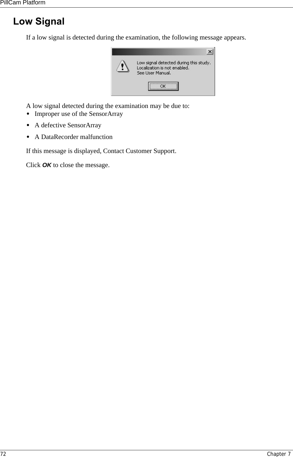
Given Imaging GIVENRECORDER Data Recorder with a connected Sensor Array User Manual RAPID 7 Setup
Given Imaging Limited Data Recorder with a connected Sensor Array RAPID 7 Setup
UserManual.wiki
>
Given Imaging
>
GIVENRECORDER User Manual
manual
Navigation menu
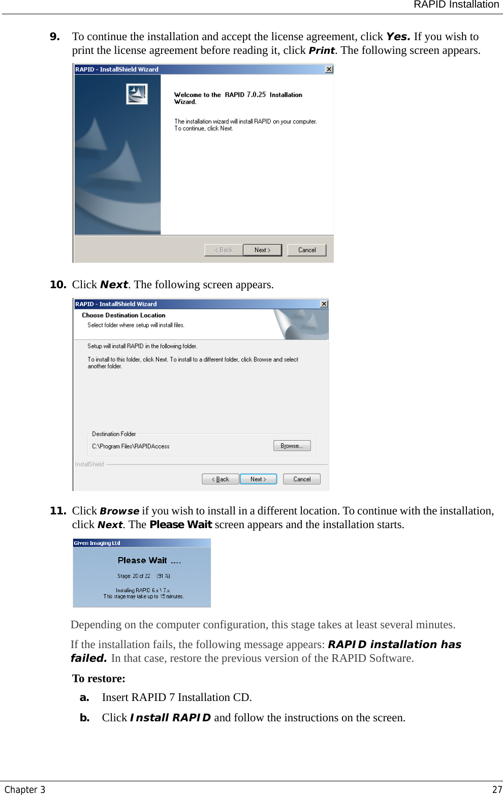
Upload a User Manual
Namespaces
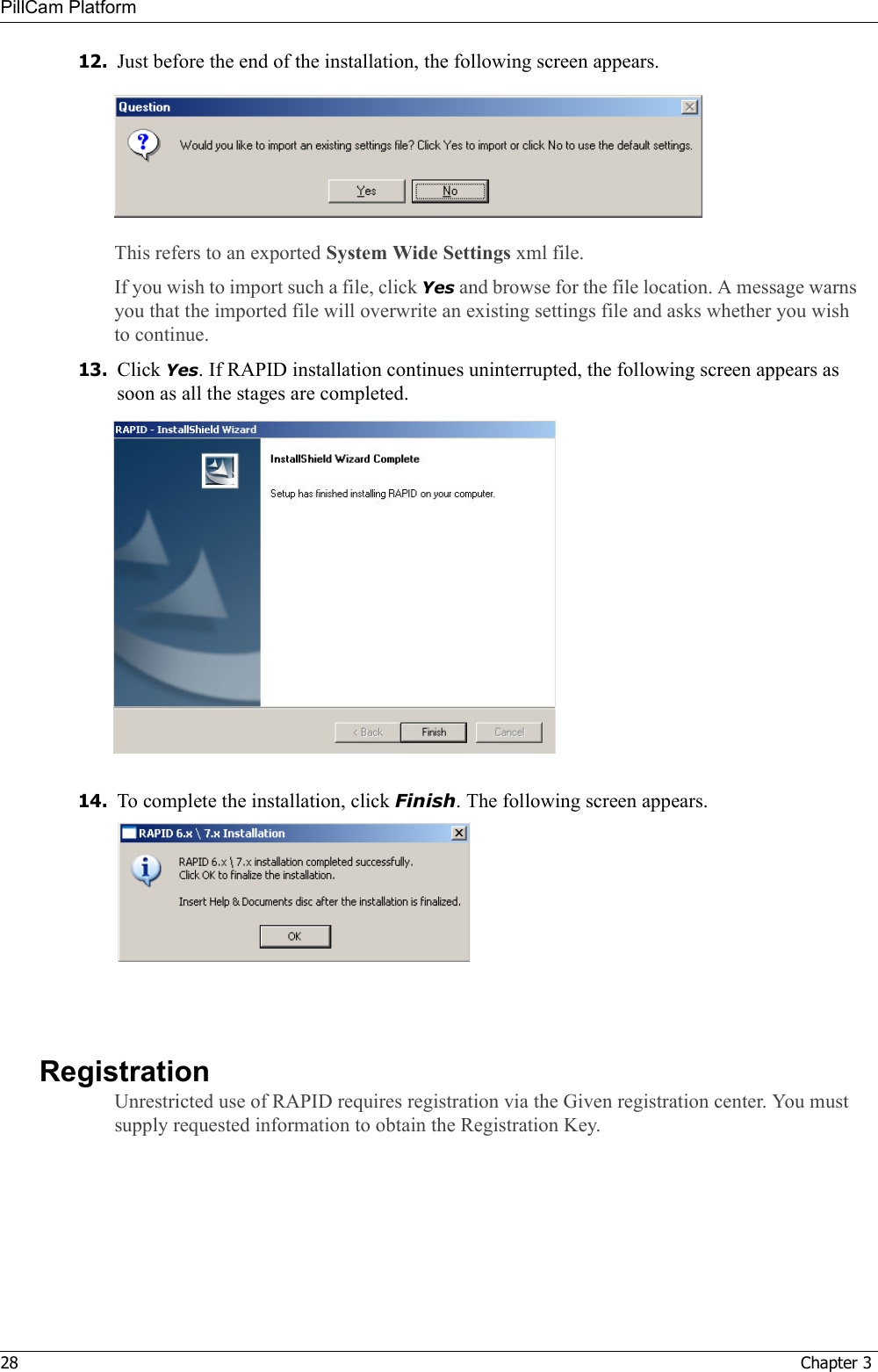
Wiki Guide
HTML
PDF
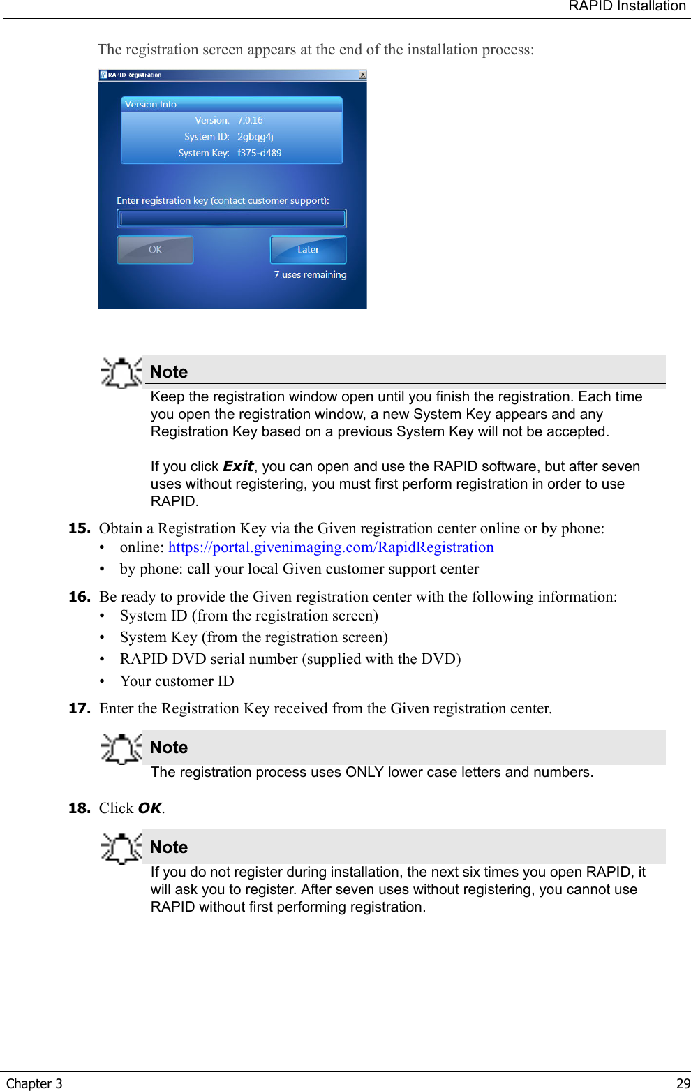
Info
Views
User Manual
Discussion / Help
Navigation

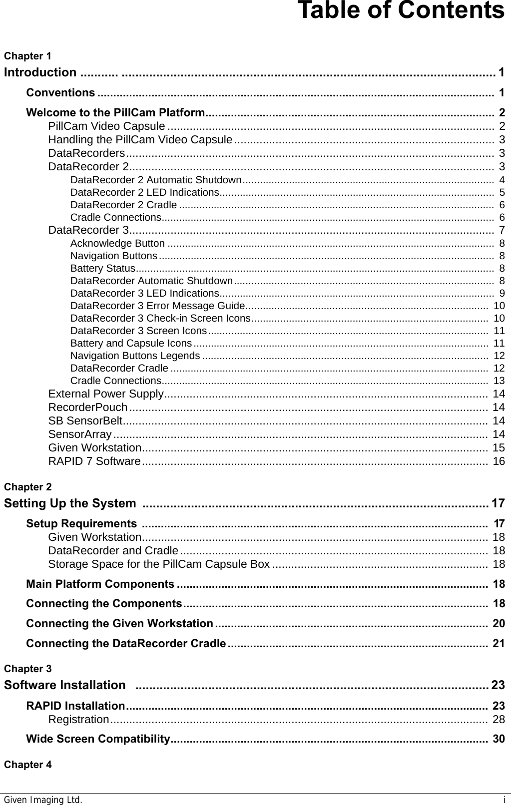


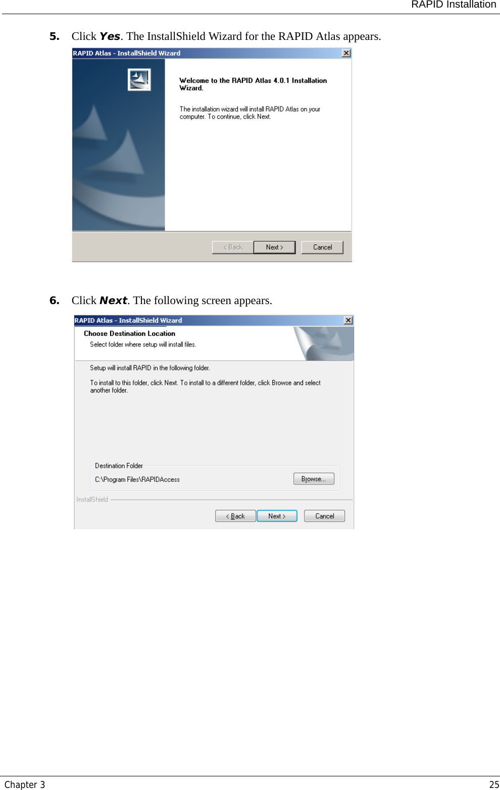
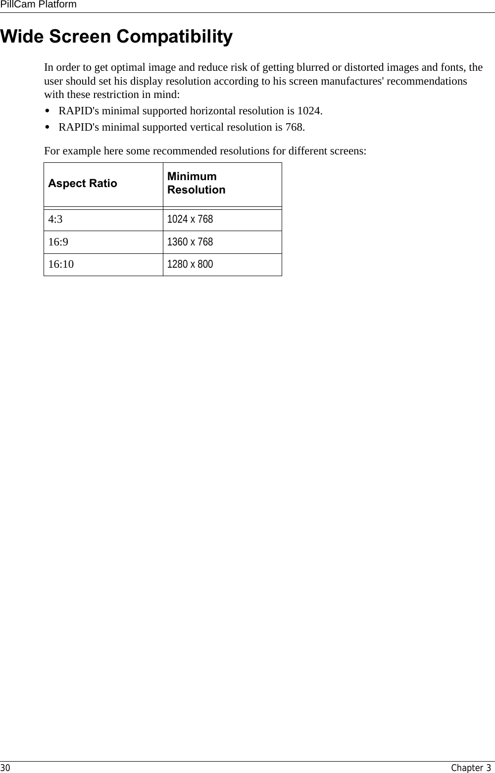
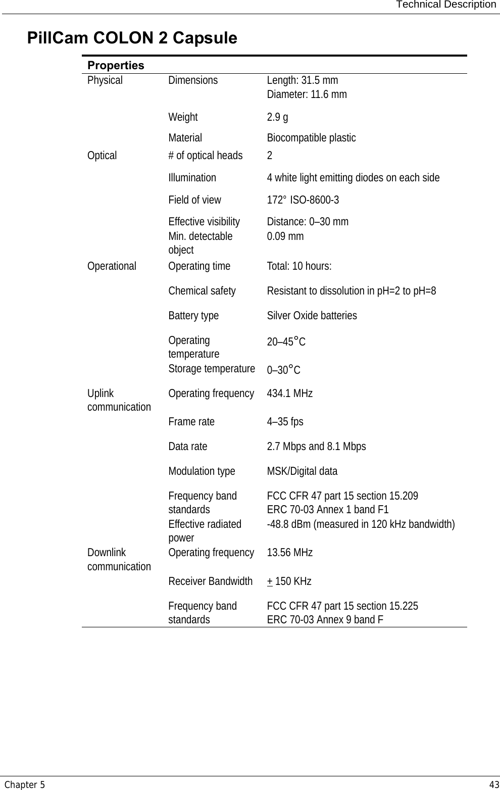
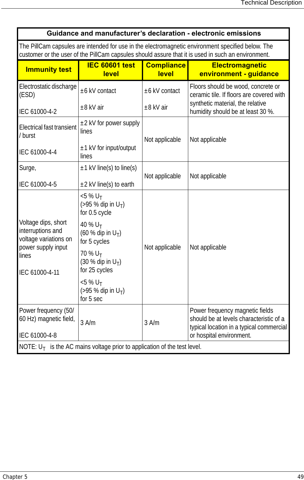
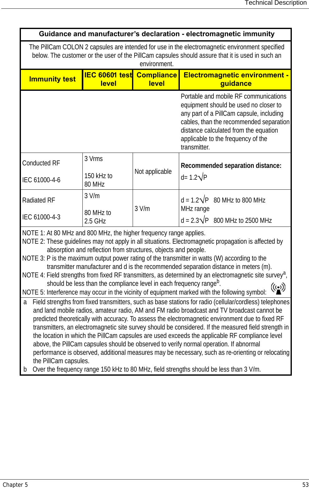
![PillCam Platform46 Chapter 5Cradle DataRecorder 2DataRecorder 3 PropertiesWeight 890 gSize (without battery inserter 14[D] x 165[W] x 97[H]mmColor blackMains power connections 1x male power cable plugpower mains range 100 to 240VPropertiesPhysical Software Proprietary firmwareRecording capacity Up to 15 hours @ LCD OFFWeight 500 g., including battery pack.Operational Power 3.5–4.2 VDC, 0.15–0.5 A Battery type Internal, Li-Ion, 3.8 V typical, 8800 mAHOperating temp. 0–40°CStorage temp. 0–55°CShielding No belt shieldingClassification • internally powered (complies with requirements for Class I equipment while connected to supply mains through charger)• Type BF applied part• Ordinary equipmentReceiver (Rx) Operating frequency 434.1 MHzBandwidth of the receiving section in this band 10 MHzTransmitter Operating frequency 13.56 MHzFrequency band ISMModulation type Linear ChirpType of modulated signal Digital dataFrequency of modulating signal 20.25 dBmEffective radiated power -27.4 dBm](https://usermanual.wiki/Given-Imaging/GIVENRECORDER/User-Guide-1393045-Page-52.png)
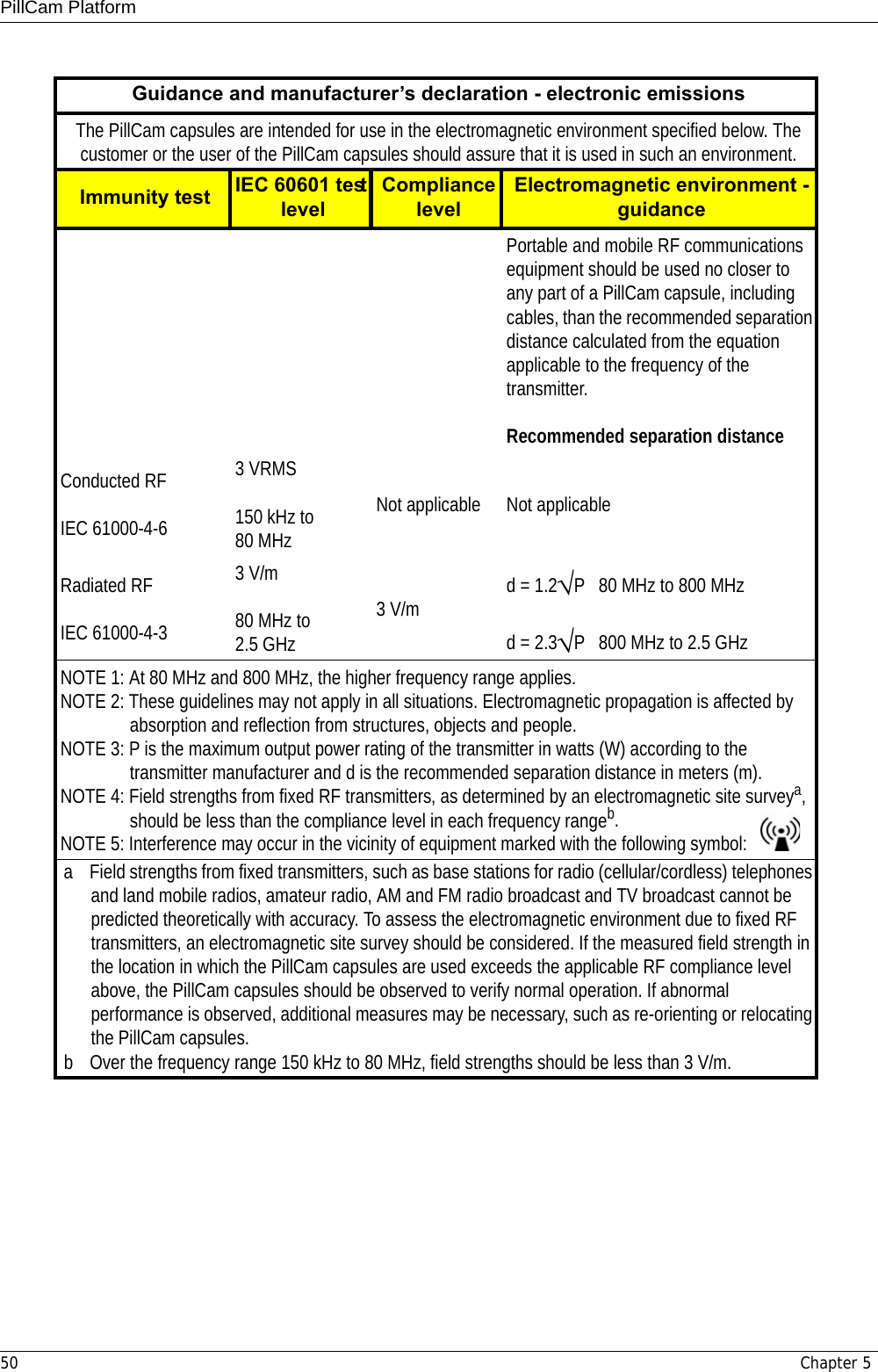
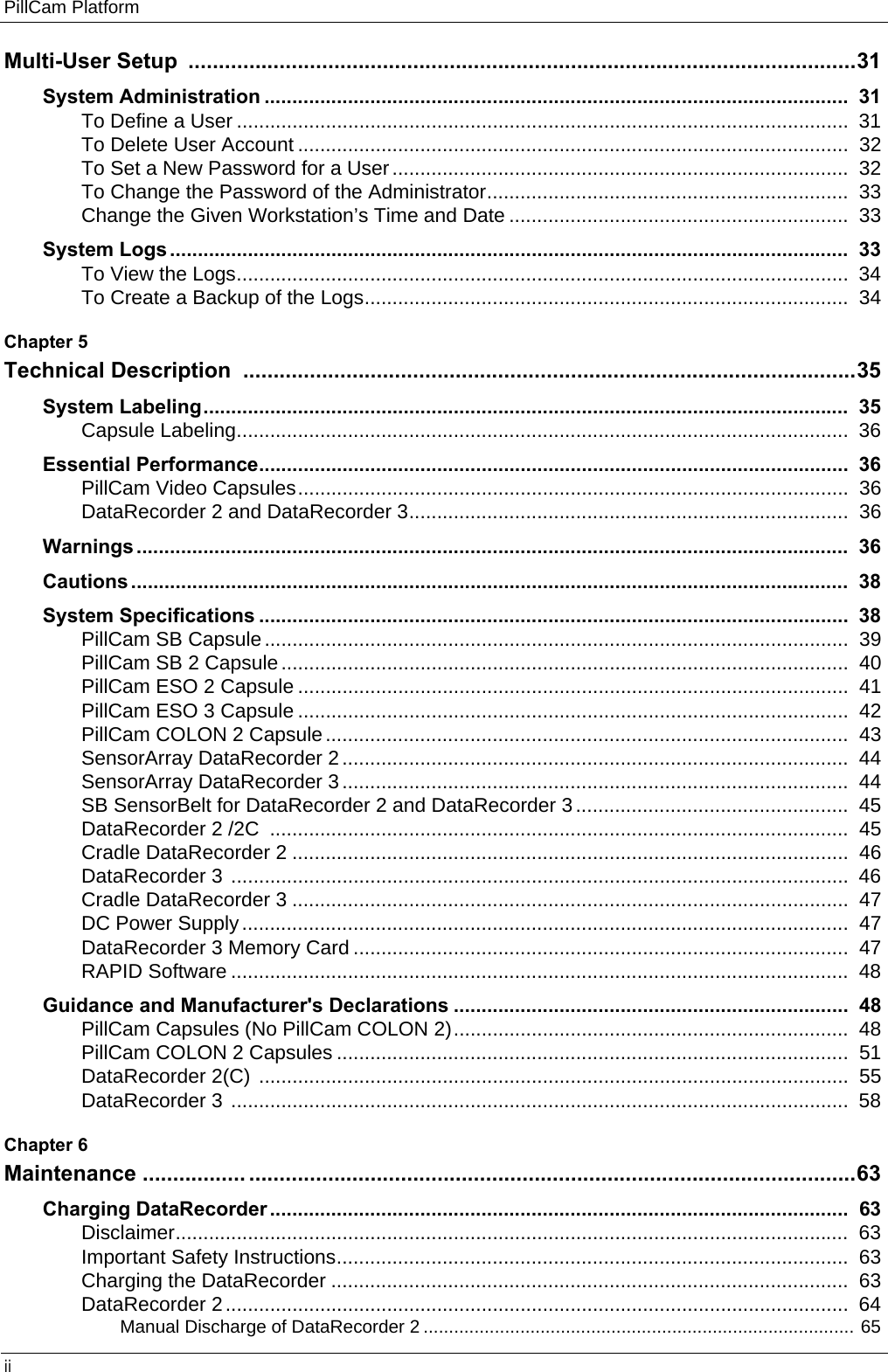
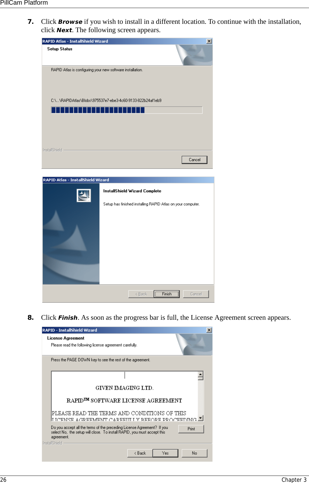
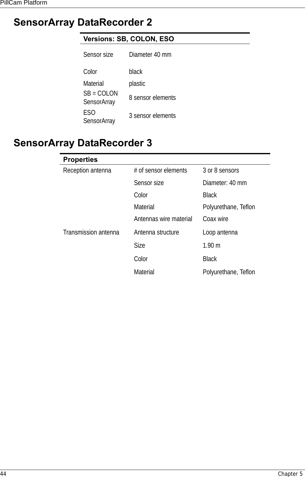
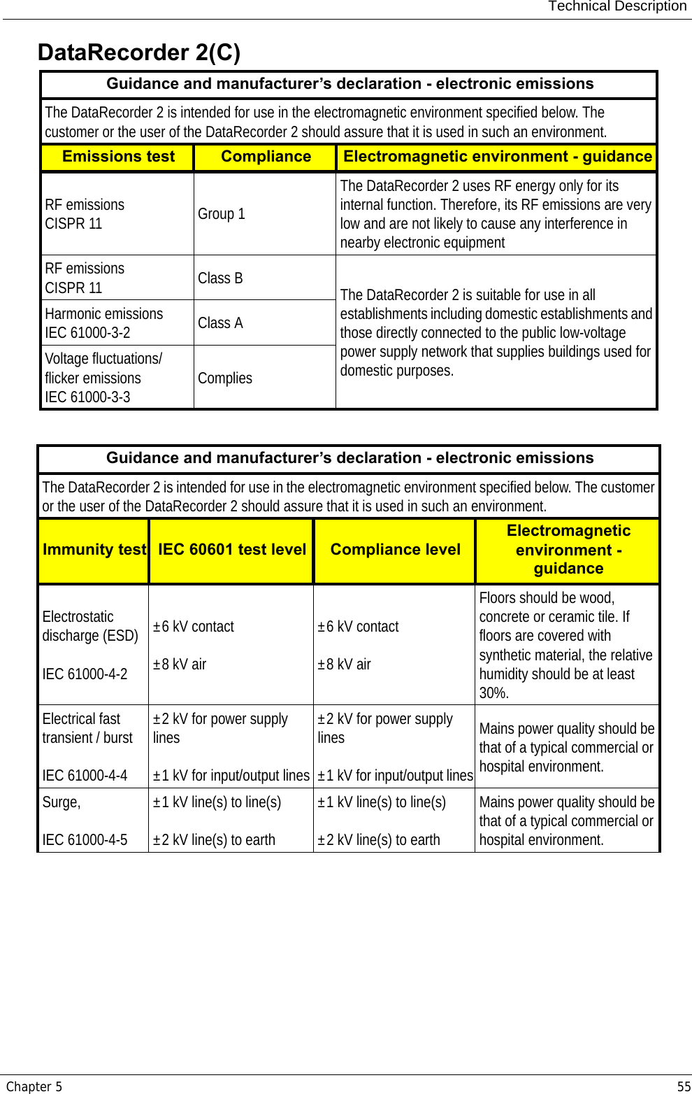
![Technical DescriptionChapter 5 51PillCam COLON 2 Capsules Recommended separation distances between portable and mobile RF communications equipment and the PillCam capsulesThe PillCam capsules are intended for use in an electromagnetic environment in which radiated RF disturbances are controlled. The customer or the user of the PillCam capsules can help prevent electromagnetic interference by maintaining a minimum distance between portable and mobile RF communications equipment (transmitters) and the PillCam capsules as recommended below, according to the maximum output power of the communications equipment.Rated maximum output power of transmitter [W]Separation distance according to frequency of transmitter [m]150 kHz to 80 MHzd = 1.2 P80 MHz to 800 MHzd = 1.2 P800 MHz to 2,5 GHzd = 2.3 P0.01 Not applicable 0.12 0.230.1 Not applicable 0.38 0.731 Not applicable 1.2 2.310 Not applicable 3.8 7.3100 Not applicable 12 23For transmitters rated at a maximum output power not listed above, the recommended separation distance d in meters (m) can be determined using the equation applicable to the frequency of the transmitter, where P is the maximum output power rating of the transmitter in watts (W) according to the transmitter manufacturer.NOTE 1: At 80 MHz and 800 MHz, the separation distance for the higher frequency range applies.NOTE 2: These guidelines may not apply in all situations. Electromagnetic propagation is affected by absorption and reflection from structures, objects and people.Guidance and manufacturer’s declaration - electromagnetic emissionsThe PillCam COLON 2 capsules are intended for use in the electromagnetic environment specified below. The customer or the user of the PillCam COLON 2 capsules capsule should assure that it is used in such an environment.Emissions test Compliance Electromagnetic environment - guidanceRF emissionsCISPR 11 Group 1The PillCam COLON 2 capsules use RF energy only for its internal function. Therefore, its RF emissions are very low and are not likely to cause any interference in nearby electronic equipmentRF emissionsCISPR 11 Class B The PillCam capsules are suitable for use in all establishments including domestic establishments and those directly connected to the public low-voltage power supply network that supplies buildings used for domestic purposes.Harmonic emissionsIEC 61000-3-2 Not applicableVoltage fluctuations/flicker emissionsIEC 61000-3-3 Not applicable](https://usermanual.wiki/Given-Imaging/GIVENRECORDER/User-Guide-1393045-Page-57.png)
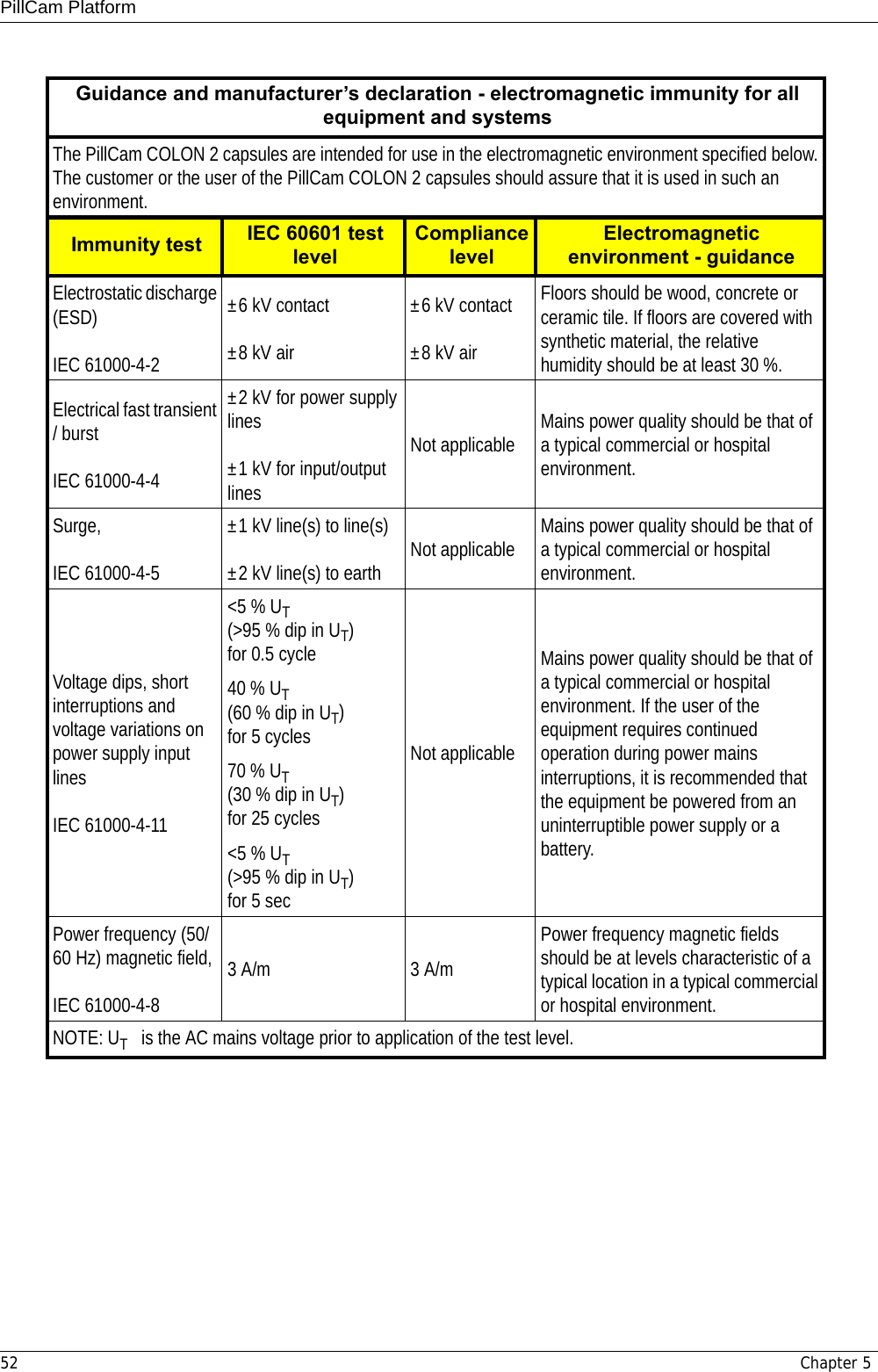
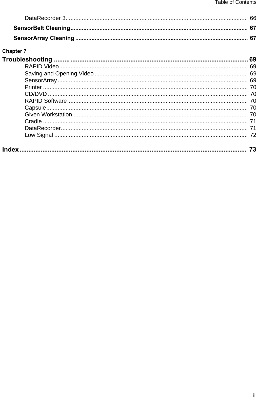
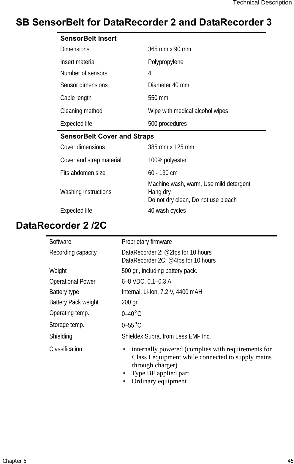
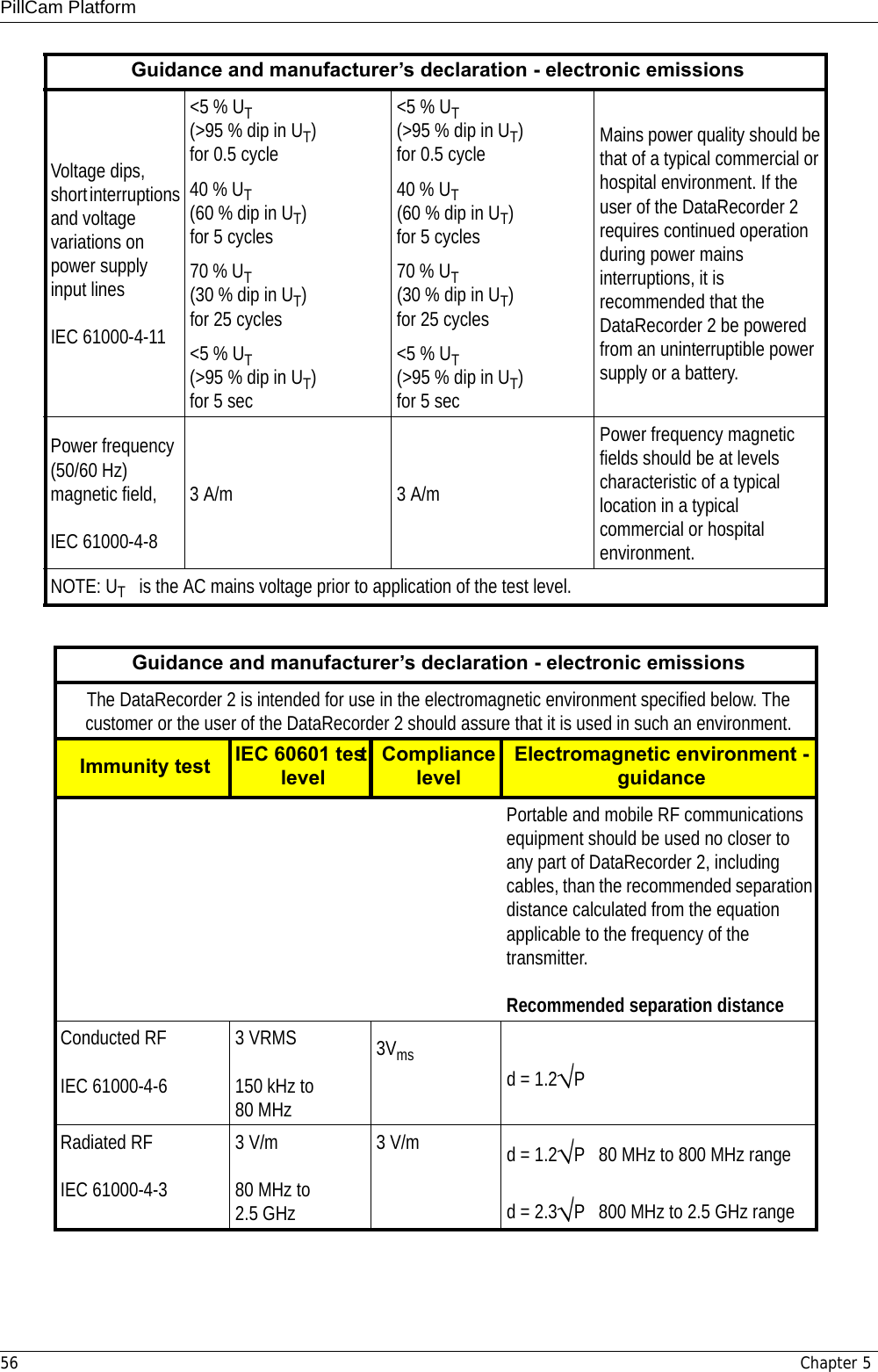
![PillCam Platform54 Chapter 5Recommended separation distances between portable and mobile RF communications equipment and the PillCam COLON 2 capsulesThe PillCam COLON 2 capsules are intended for use in an electromagnetic environment in which radiated RF disturbances are controlled. The customer or the user of the PillCam COLON 2 capsules can help prevent electromagnetic interference by maintaining a minimum distance between portable and mobile RF communications equipment (transmitters) and the PillCam COLON 2 capsules as recommended below, according to the maximum output power of the communications equipment.Rated maximum output power of transmitter [W]Separation distance according to frequency of transmitter [m]150 kHz to 80 MHzd = 1.2 P80 MHz to 800 MHzd = 1.2 P800 MHz to 2,5 GHzd = 2.3 P0.01 0.12 0.12 0.230.1 0.38 0.38 0.7311.2 1.2 2.310 3.8 3.8 7.3100121223For transmitters rated at a maximum output power not listed above, the recommended separation distance d in meters (m) can be determined using the equation applicable to the frequency of the transmitter, where P is the maximum output power rating of the transmitter in watts (W) according to the transmitter manufacturer.NOTE 1: At 80 MHz and 800 MHz, the separation distance for the higher frequency range applies.NOTE 2: These guidelines may not apply in all situations. Electromagnetic propagation is affected by absorption and reflection from structures, objects and people.](https://usermanual.wiki/Given-Imaging/GIVENRECORDER/User-Guide-1393045-Page-60.png)
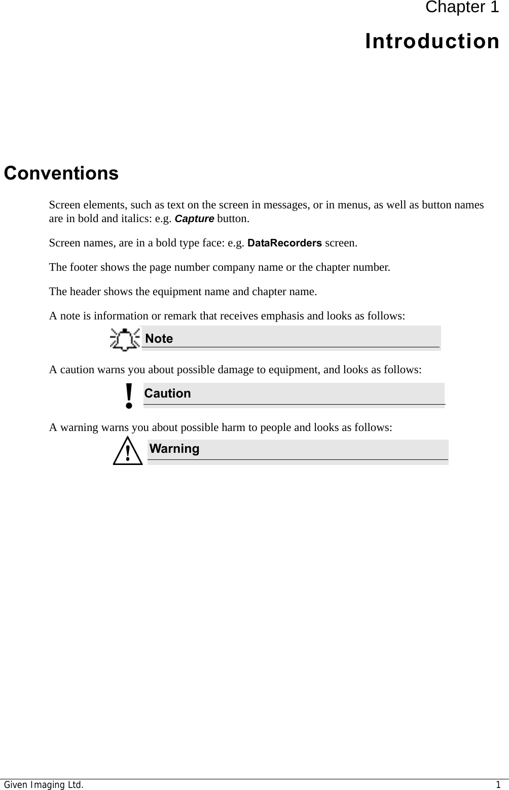
![Technical DescriptionChapter 5 57NOTE 1: At 80 MHz and 800 MHz, the higher frequency range applies.NOTE 2: These guidelines may not apply in all situations. Electromagnetic propagation is affected by absorption and reflection from structures, objects and people.NOTE 3: P is the maximum output power rating of the transmitter in watts (W) according to the transmitter manufacturer and d is the recommended separation distance in meters (m). NOTE 4: Field strengths from fixed RF transmitters, as determined by an electromagnetic site surveya, should be less than the compliance level in each frequency rangeb.NOTE 5: Interference may occur in the vicinity of equipment marked with the following symbol: a Field strengths from fixed transmitters, such as base stations for radio (cellular/cordless) telephones and land mobile radios, amateur radio, AM and FM radio broadcast and TV broadcast cannot be predicted theoretically with accuracy. To assess the electromagnetic environment due to fixed RF transmitters, an electromagnetic site survey should be considered. If the measured field strength in the location in which the DataRecorder 2 is used exceeds the applicable RF compliance level above, the DataRecorder 2 should be observed to verify normal operation. If abnormal performance is observed, additional measures may be necessary, such as re-orienting or relocating the DataRecorder 2.b Over the frequency range 150 kHz to 80 MHz, field strengths should be less than 3 V/m.Recommended separation distances between portable and mobile RF communications equipment and the PillCam ESO capsuleThe DataRecorder 2 is intended for use in an electromagnetic environment in which radiated RF disturbances are controlled. The customer or the user of the DataRecorder 2 can help prevent electromagnetic interference by maintaining a minimum distance between portable and mobile RF communications equipment (transmitters) and the DataRecorder 2 as recommended below, according to the maximum output power of the communications equipment.Rated maximum output power of transmitter [W]Separation distance according to frequency of transmitter [m]150 kHz to 80 MHzd = 1.2 P80 MHz to 800 MHzd = 1.2 P800 MHz to 2,5 GHzd = 2.3 P0.01 Not applicable 0.12 0.230.1 Not applicable 0.38 0.731 Not applicable 1.2 2.310 Not applicable 3.8 7.3100 Not applicable 12 23For transmitters rated at a maximum output power not listed above, the recommended separation distance d in meters (m) can be determined using the equation applicable to the frequency of the transmitter, where P is the maximum output power rating of the transmitter in watts (W) according to the transmitter manufacturer.NOTE 1: At 80 MHz and 800 MHz, the separation distance for the higher frequency range applies.NOTE 2: These guidelines may not apply in all situations. Electromagnetic propagation is affected by absorption and reflection from structures, objects and people.Guidance and manufacturer’s declaration - electronic emissions](https://usermanual.wiki/Given-Imaging/GIVENRECORDER/User-Guide-1393045-Page-63.png)
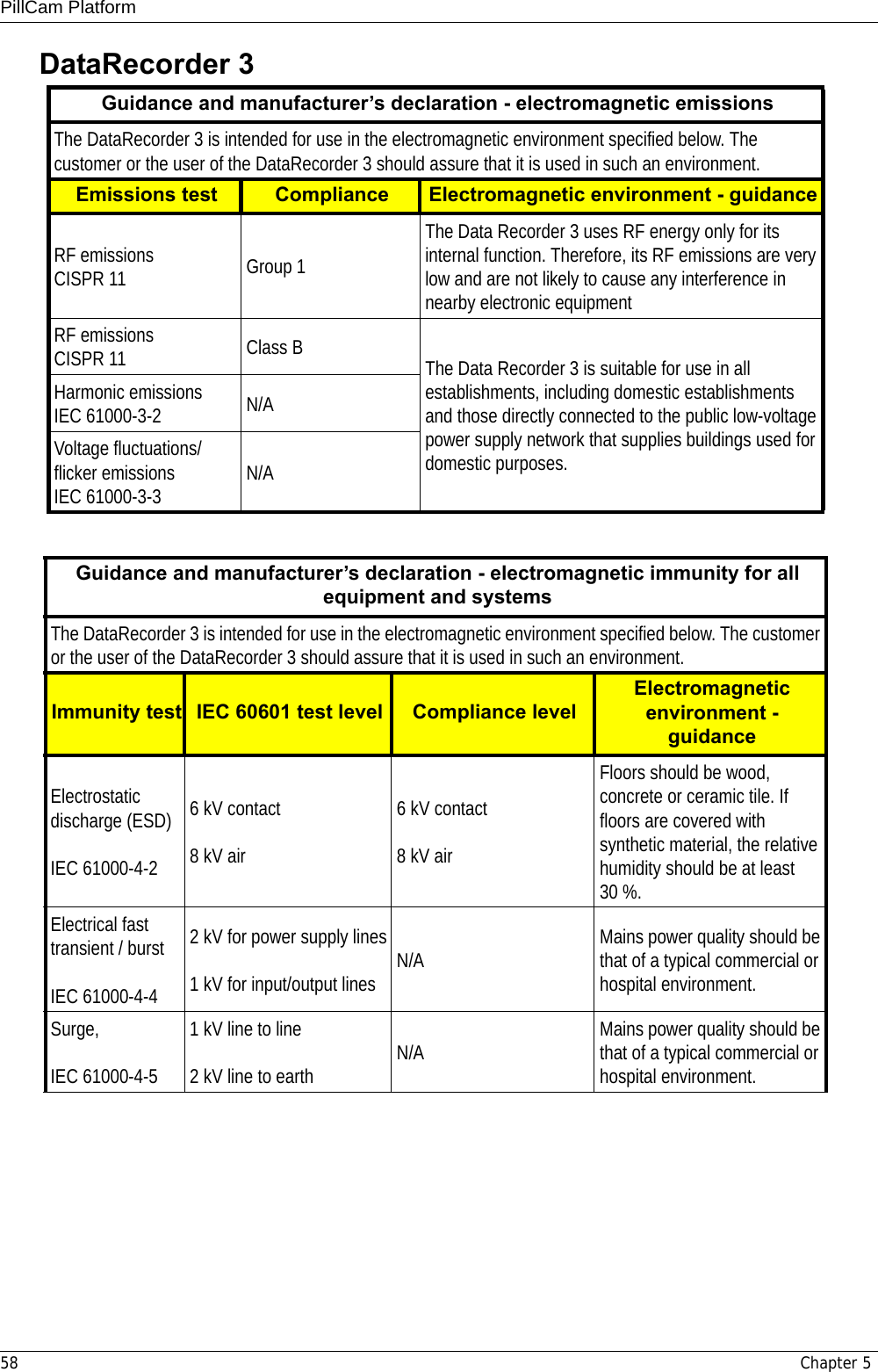
![PillCam Platform60 Chapter 5Guidance and manufacturer’s declaration - electromagnetic immunityThe DataRecorder 3 is intended for use in the electromagnetic environment specified below. The customer or the user of the DataRecorder 3 should assure that it is used in such an environment.Immunity test IEC 60601 test levelCompliance levelElectromagnetic environment - guidancePortable and mobile RF communications equipment should be used no closer to any part of DataRecorder 3, including cables, than the recommended separation distance calculated from the equation applicable to the frequency of the transmitter.Conducted RF,IEC 61000-4-63Vrms150 kHz to80 MHz3Vrms150 kHz to80 MHzRecommended separation distance:d = 1.2 PRadiated RF,IEC 61000-4-33 V/m80 MHz to2.5 GHz[E1] = 3 V/m Recommended separation distance:d = 1.2 P 80 MHz to 800 MHz ranged = 2.3 P 800 MHz to 2500 MHz rangeNOTE 1: At 80 MHz and 800 MHz, the higher frequency range applies.NOTE 2: These guidelines may not apply in all situations. Electromagnetic propagation is affected by absorption and reflection from structures, objects and people.NOTE 3: P is the maximum output power rating of the transmitter in watts (W) according to the transmitter manufacturer and d is the recommended separation distance in meters (m). NOTE 4: Field strengths from fixed RF transmitters, as determined by an electromagnetic site surveya, should be less than the compliance level in each frequency rangeb.NOTE 5: Interference may occur in the vicinity of equipment marked with the following symbol: a Field strengths from fixed transmitters, such as base stations for radio (cellular/cordless) telephones and land mobile radios, amateur radio, AM and FM radio broadcast and TV broadcast cannot be predicted theoretically with accuracy. To assess the electromagnetic environment due to fixed RF transmitters, an electromagnetic site survey should be considered. If the measured field strength in the location in which the DataRecorder 3 is used exceeds the applicable RF compliance level above, the DataRecorder 3 should be observed to verify normal operation. If abnormal performance is observed, additional measures may be necessary, such as re-orienting or relocating the DataRecorder 3.b Over the frequency range 150 kHz to 80 MHz, field strengths should be less than 3 V/m.](https://usermanual.wiki/Given-Imaging/GIVENRECORDER/User-Guide-1393045-Page-66.png)
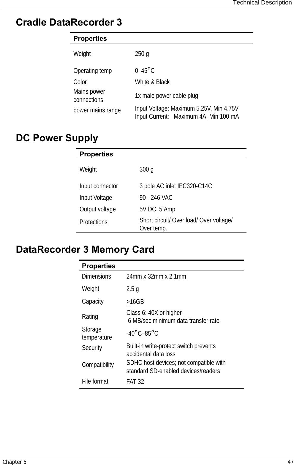
![Technical DescriptionChapter 5 61Recommended separation distances between portable and mobile RF communications equipment and the DataRecorder 3The DataRecorder 3 is intended for use in an electromagnetic environment in which radiated RF disturbances are controlled. The customer or the user of the DataRecorder 3 can help prevent electromagnetic interference by maintaining a minimum distance between portable and mobile RF communications equipment (transmitters) and the DataRecorder 3 as recommended below, according to the maximum output power of the communications equipment.Rated maximum output power of transmitter [W]Separation distance according to frequency of transmitter [m]150 kHz to 80 MHzd = 1.2 P80 MHz to 800 MHzd = 1.2 P800 MHz to 2,5 GHzd = 2.3 P0.01 0.12 0.12 0.230.1 0.38 0.38 0.731 1.2 1.2 2.310 3.8 3.8 7.3100 12 12 23For transmitters rated at a maximum output power not listed above, the recommended separation distance d in meters (m) can be determined using the equation applicable to the frequency of the transmitter, where P is the maximum output power rating of the transmitter in watts (W) according to the transmitter manufacturer.NOTE 1: At 80 MHz and 800 MHz, the separation distance for the higher frequency range applies.NOTE 2: These guidelines may not apply in all situations. Electromagnetic propagation is affected by absorption and reflection from structures, objects and people.](https://usermanual.wiki/Given-Imaging/GIVENRECORDER/User-Guide-1393045-Page-67.png)