Glenayre Electronics GL-T8200 Low Power Transmitter for 1 and 2way wireless data User Manual
Glenayre Electronics Inc Low Power Transmitter for 1 and 2way wireless data
Contents
- 1. Composite of users manuals
- 2. Exciter manual
Composite of users manuals
Print Date: 03/23/99 Copyright © 1999 Glenayre
GL-T8200 1- to 25-Watt 900-MHz Power Amplifier Rev. A: 03/23/99
Specifications subject to change without notice
Copyright © 1999 Glenayre
All rights reserved. No part of this work may be reproduced or copied in any form or by
any means—graphic, electronic, or mechanical, including photocopying, recording,
taping, or information-retrieval system—without written permission of Glenayre.
GL-T8200
1- to 25-Watt, 900-MHz Power Amplifier
USER MANUAL
PN 9110.01306
REV A
GL-T8200 1- to 25-Watt 900-MHz Power Amplifier Glenayre Document Number: 9110.01306
Document Change Record Rev. A: 03/23/99
Copyright © 1999 Glenayre Print Date: 03/23/99
Document Change Record
Revision: Revision A
Date: 03/23/99
Changes: none, original

Glenayre Document Number: 9110.01306 GL-T8200 1- to 25-Watt 900-MHz Power Amplifier
Rev. A: 03/23/99 Table of Contents
25w82001.toc
Print Date: 04/14/99 Copyright © 1999 Glenayre Page: -i
Table of Contents
1 GENERAL . . . . . . . . . . . . . . . . . . . . . . . . . . . . . . . . . . . . 1-1
1.1 Manual Scope . . . . . . . . . . . . . . . . . . . . . . . . 1-1
1.2 Applicable Documents. . . . . . . . . . . . . . . . . . . . . 1-1
1.3 Manual Sections . . . . . . . . . . . . . . . . . . . . . . . 1-1
2 SPECIFICATIONS . . . . . . . . . . . . . . . . . . . . . . . . . . . . . . . . 2-1
3 DESCRIPTION . . . . . . . . . . . . . . . . . . . . . . . . . . . . . . . . . . 3-1
3.1 Physical Description. . . . . . . . . . . . . . . . . . . . . . 3-1
3.1.1 Mounting Provisions . . . . . . . . . . . . . . . . . . . . . . . .3-1
3.1.2 PA Chassis Rear Connector Panel . . . . . . . . . . . . . . . . .3-1
3.2 Functional Description. . . . . . . . . . . . . . . . . . . . . 3-3
3.2.1 RF Path . . . . . . . . . . . . . . . . . . . . . . . . . . . . . . .3-3
3.2.2 Signal and Power Connections . . . . . . . . . . . . . . . . . . .3-3
3.2.3 Isolator . . . . . . . . . . . . . . . . . . . . . . . . . . . . . . .3-4
4 INSTALLATION AND SETUP . . . . . . . . . . . . . . . . . . . . . . . . . 4-1
4.1 Cabinet Installation and External Cabling . . . . . . . . . . . . . 4-1
4.1.1 Tools and Equipment Required . . . . . . . . . . . . . . . . . . .4-1
4.1.2 Inspection . . . . . . . . . . . . . . . . . . . . . . . . . . . . . .4-1
4.1.3 Rack Positioning . . . . . . . . . . . . . . . . . . . . . . . . . .4-1
4.1.4 External Cabinet Equipment Cabling . . . . . . . . . . . . . . . .4-1
4.1.5 PA I/O Connections. . . . . . . . . . . . . . . . . . . . . . . . .4-2
4.2 Setup. . . . . . . . . . . . . . . . . . . . . . . . . . . . 4-3
4.2.1 Expected Exciter . . . . . . . . . . . . . . . . . . . . . . . . . .4-3
4.2.2 Setup Using VDT . . . . . . . . . . . . . . . . . . . . . . . . . .4-3
5 OPERATION . . . . . . . . . . . . . . . . . . . . . . . . . . . . . . . . . . . 5-1
5.1 Controls and Indicators . . . . . . . . . . . . . . . . . . . . 5-1
5.2 Operation . . . . . . . . . . . . . . . . . . . . . . . . . . 5-1
5.2.1 Turn PA On and Off . . . . . . . . . . . . . . . . . . . . . . . .5-1
5.2.2 Turn Fan On and Off . . . . . . . . . . . . . . . . . . . . . . . .5-1
5.2.3 Key and Unkey PA . . . . . . . . . . . . . . . . . . . . . . . . .5-1
6 THEORY OF OPERATION . . . . . . . . . . . . . . . . . . . . . . . . . . . 6-1
6.1 Power Distribution . . . . . . . . . . . . . . . . . . . . . . 6-1
6.1.1 Fan Power . . . . . . . . . . . . . . . . . . . . . . . . . . . . . .6-1
6.1.2 High-Current Power to PA Board. . . . . . . . . . . . . . . . . .6-1
6.1.3 Metering Circuit Regulators . . . . . . . . . . . . . . . . . . . .6-1
6.2 RF Flow . . . . . . . . . . . . . . . . . . . . . . . . . . 6-1
GL-T8200 1- to 25-Watt 900-MHz Power Amplifier Glenayre Document Number: 9110.01306
Table of Contents Rev. A: 03/23/99
Page: -ii Copyright © 1999 Glenayre Print Date: 04/14/99
6.3 PA Board . . . . . . . . . . . . . . . . . . . . . . . . . 6-2
6.3.1 Input Voltage . . . . . . . . . . . . . . . . . . . . . . . . . . . . 6-3
6.3.2 Internally Generated Voltages . . . . . . . . . . . . . . . . . . 6-3
6.4 Exciter Interface . . . . . . . . . . . . . . . . . . . . . . . 6-5
6.4.1 Exciter Interface Connector Pinout. . . . . . . . . . . . . . . . . 6-5
6.5 Analog Readings Thresholds . . . . . . . . . . . . . . . . . . 6-5
6.5.1 PA Board Currents . . . . . . . . . . . . . . . . . . . . . . . . . 6-6
6.5.2 PA Forward Power . . . . . . . . . . . . . . . . . . . . . . . . . 6-6
6.5.3 PA Reflected Power . . . . . . . . . . . . . . . . . . . . . . . . 6-6
6.5.4 PA Board RF Input Power . . . . . . . . . . . . . . . . . . . . . 6-6
6.5.5 +28-Volt External Supply . . . . . . . . . . . . . . . . . . . . . 6-6
6.5.6 +36-Volt Internal Supply . . . . . . . . . . . . . . . . . . . . . . 6-6
6.5.7 +5-Volt Internal Supplies. . . . . . . . . . . . . . . . . . . . . . 6-7
6.5.8 Temperature . . . . . . . . . . . . . . . . . . . . . . . . . . . . 6-7
7 MAINTENANCE . . . . . . . . . . . . . . . . . . . . . . . . . . . . . . . . . 7-1
7.1 Cleaning . . . . . . . . . . . . . . . . . . . . . . . . . . 7-1
7.2 Power Calibration . . . . . . . . . . . . . . . . . . . . . . 7-1
8 CHECKOUT AND TROUBLESHOOTING . . . . . . . . . . . . . . . . . . 8-1
8.1 Introduction . . . . . . . . . . . . . . . . . . . . . . . . 8-1
8.2 Checkout Procedures . . . . . . . . . . . . . . . . . . . . . 8-1
8.2.1 VDT Power-Up Verification . . . . . . . . . . . . . . . . . . . . 8-1
8.2.2 Dc Voltage Verification . . . . . . . . . . . . . . . . . . . . . . 8-1
8.3 Troubleshooting Procedures . . . . . . . . . . . . . . . . . . 8-1
8.3.1 Parameter Readings at Time of Fault. . . . . . . . . . . . . . . . 8-1
8.3.2 GL-C2000 Transmitter Controller Alarms . . . . . . . . . . . . . 8-2
8.3.3 Operational Checks . . . . . . . . . . . . . . . . . . . . . . . . . 8-2
8.3.4 Power Amplifier Current Measurement . . . . . . . . . . . . . . 8-2
9 REMOVAL AND REINSTALLATION . . . . . . . . . . . . . . . . . . . . 9-1
9.1 PA . . . . . . . . . . . . . . . . . . . . . . . . . . . . 9-1
9.1.1 Removal . . . . . . . . . . . . . . . . . . . . . . . . . . . . . . 9-1
9.1.2 Reinstallation . . . . . . . . . . . . . . . . . . . . . . . . . . . . 9-1

Glenayre Document Number: 9110.01306 GL-T8200 1- to 25-Watt 900-MHz Power Amplifier
Rev. A: 03/23/99 List of Figures
25w82001.lof
Print Date: 04/14/99 Copyright © 1999 Glenayre Page: -iii
List of Figures
Figure 3-1 PA Front Isometric View . . . . . . . . . . . . . . . . . . . . . . . . . 3-2
Figure 3-2 Top View of PA RF Compartments, Showing Internal Assemblies . . . 3-3
Figure 4-1 PA Rear View. . . . . . . . . . . . . . . . . . . . . . . . . . . . . . . 4-4
Figure 6-1 Simplified Power Amplifier Block Diagram . . . . . . . . . . . . . . . 6-2
Figure 6-2 PA Board Functional Diagram . . . . . . . . . . . . . . . . . . . . . . 6-4
GL-T8200 1- to 25-Watt 900-MHz Power Amplifier Glenayre Document Number: 9110.01306
List of Figures Rev. A: 03/23/99
Page: -iv Copyright © 1999 Glenayre Print Date: 04/14/99

Glenayre Document Number: 9110.01306 GL-T8200 1- to 25-Watt 900-MHz Power Amplifier
Rev. A: 03/23/99 List of Tables
25w82001.lot
Print Date: 04/14/99 Copyright © 1999 Glenayre Page: -v
List of Tables
Table 1-1 Applicable Documents . . . . . . . . . . . . . . . . . . . . . . . . . . 1-1
Table 1-2 Manual Sections . . . . . . . . . . . . . . . . . . . . . . . . . . . . . 1-2
Table 2-1 Power Amplifier Specifications. . . . . . . . . . . . . . . . . . . . . . 2-1
Table 4-1 Required Tools and Equipment. . . . . . . . . . . . . . . . . . . . . . 4-1
Table 4-2 PA I/O Connections. . . . . . . . . . . . . . . . . . . . . . . . . . . . 4-2
Table 4-3 Exciter/PA Connector Pinout (For DSP Exciter) . . . . . . . . . . . . . 4-3
Table 4-4 PA Board Fuses . . . . . . . . . . . . . . . . . . . . . . . . . . . . . . 4-5
Table 6-1 PA Board Voltages . . . . . . . . . . . . . . . . . . . . . . . . . . . . 6-1
Table 6-2 Metered Parameter Thresholds . . . . . . . . . . . . . . . . . . . . . . 6-7
Table 8-1 PA Board Current . . . . . . . . . . . . . . . . . . . . . . . . . . . . . 8-2
GL-T8200 1- to 25-Watt 900-MHz Power Amplifier Glenayre Document Number: 9110.01306
List of Tables Rev. A: 03/23/99
Page: -vi Copyright © 1999 Glenayre Print Date: 04/14/99

Glenayre Document Number: 9110.01306 GL-T8200 1- to 25-Watt 900-MHz Power Amplifier
Rev. A: 03/23/99 GENERAL
25w82001
Print Date: 05/10/99 Copyright © 1999 Glenayre Page: 1-1
1
GENERAL
1.1 Manual Scope
This manual provides information for the 1 to 25-watt, 900-MHz power amplifier, part
number 1000.02186.
1.2 Applicable Documents
This manual is incomplete without additional manuals. Refer to Table 1-1 for a listing and
function of these manuals.
1.3 Manual Sections
Table 1-2 lists the sections of this manual with a summary of their contents.
Table 1-1 Applicable Documents
document part number function
GL-T8200 system manual 9110.01305 describes fully racked-up GL-
T8200 transmitter
DSP VDT manual 9110.00259 describes DSP exciter software in-
stalled in exciter
DSP exciter user manual 9110.01021 describes DSP exciter hardware
equipment in transmitter
GL-T8200 1 to 25-watt PA
manual 9110.01306 this manual
power supply manual 9110.00622 describes GL2728 power supply
equipment

GL-T8200 1- to 25-Watt 900-MHz Power Amplifier Glenayre Document Number: 9110.01306
GENERAL Rev. A: 03/23/99
Page: 1-2 Copyright © 1999 Glenayre Print Date: 05/10/99
Table 1-2 Manual Sections
section contents
1. General introduction and purpose of manual
2. Specifications significant measurements of power amplifier
3. Description introduction and principal characteristics of power
amplifier
4. Installation and Setup initial installation and activation of power amplifier
5. Operation operation of power amplifier
6. Theory of Operation detailed functional description of circuitry within
power amplifier
7. Maintenance procedures to be performed on specific intervals to
maintain optimum performance of power amplifier
8. Checkout and Troubleshooting verification of proper operation, correction to proper
operation of power amplifier
9. Removal and Reinstallation removal and reinstallation procedures for the PA

Glenayre Document Number: 9110.01306 GL-T8200 1- to 25-Watt 900-MHz Power Amplifier
Rev. A: 03/23/99 SPECIFICATIONS
25w82002
Print Date: 03/29/99 Copyright © 1999 Glenayre Page: 2-1
2 SPECIFICATIONS
Table 2-1 lists the significant equipment-level specifications for the power amplifier.
Table 2-1 Power Amplifier Specifications
measurement condition specification
Electrical
RF output power (W) continuous, at
output of PA 1 to 25
RF bandwidth (MHz) exceeds exciter bandwidth
RF input power (mW) factory-set
attenuation 200-400
RF input connector type-N female
RF output connector output of PA type-N female
input and output RF
impedance (ohms) 50
VSWR max 1.5
dc input power
voltage (Vdc)
current, idle/operating (A) 28
Mechanical and Environmental
humidity 5 to 95%, noncondensing
ambient storage temperature -30o to 70oC
ambient operating
temperature -30o to 60oC
temperature derating factor
above 5000 feet (1500 m) 0.5oC per 100 m
vibration Mil-Std 810E, Method 514.4
Category 1
maximum operating
elevation to 10,000 ft (3050 m)
height 3 RU (5.25 in, 13.4 cm)
width 19 in (48 cm)
depth 12 in (30.5 cm)
weight 25 lb (11.3 kg)
GL-T8200 1- to 25-Watt 900-MHz Power Amplifier Glenayre Document Number: 9110.01306
SPECIFICATIONS Rev. A: 03/23/99
Page: 2-2 Copyright © 1999 Glenayre Print Date: 03/29/99

Glenayre Document Number: 9110.01306 GL-T8200 1- to 25-Watt 900-MHz Power Amplifier
Rev. A: 03/23/99 DESCRIPTION
25w82003
Print Date: 05/10/99 Copyright © 1999 Glenayre Page: 3-1
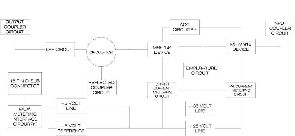
3 DESCRIPTION
This is a 1- to 25-watt PA intended for use on the 900-MHz band. This PA is characterized
by integrated monitoring devices that supply critical status information to the DSP exciter.
This exciter contains diagnostic software that can detect and report a faulty PA.
3.1 Physical Description
Refer to Figure 3-1 and Figure 3-2. The PA consists of a 3 RU high chassis, including
convection fins and one fan.
The chassis contains a PA board which contains metering circuitry, power distribution
circuitry, and RF amplification circuitry.
3.1.1 Mounting Provisions
The PA is mounted to the front of most standard 19-inch equipment racks by means of eight
screws. The front panel of the PA may by removed while the PA is mounted in the rack for
access to fuses. Thumbscrews secure the front panel to the PA.
3.1.2 PA Chassis Rear Connector Panel
Refer to Figure 4-2 for a list of connections for the PA. The PA chassis rear connector panel
has an RF input connector, an RF output connector, a dc power input connector, a dc power
output connector, a fan, and a 15-pin connector for connection to the DSP exciter.
GL-T8200 1- to 25-Watt 900-MHz Power Amplifier Glenayre Document Number: 9110.01306
DESCRIPTION Rev. A: 03/23/99
Page: 3-2 Copyright © 1999 Glenayre Print Date: 05/10/99
v0222.hgl
Figure 3-1 PA Front Isometric View

Glenayre Document Number: 9110.01306 GL-T8200 1- to 25-Watt 900-MHz Power Amplifier
Rev. A: 03/23/99 DESCRIPTION
25w82003
Print Date: 05/10/99 Copyright © 1999 Glenayre Page: 3-3
v0221.hgl
Figure 3-2 Top View of PA Board, Showing I/O
3.2 Functional Description
The RF amplifier circuitry of the power amplifier is contained within the PA chassis. The
monitoring of the RF amplifier system is accomplished by the digital exciter through the
PA board located in the PA chassis.
3.2.1 RF Path
The PA chassis receives the exciter output at a rear-mounted type-N connector on the PA
board. The RF output power leaves the PA board through a type-N RF output connector. A
jumper delivers the signal to the lightning protector output on the cabinet.
3.2.2 Signal and Power Connections
All PA dc, signal monitoring, and control signals are routed through the PA board.
GL-T8200 1- to 25-Watt 900-MHz Power Amplifier Glenayre Document Number: 9110.01306
DESCRIPTION Rev. A: 03/23/99
Page: 3-4 Copyright © 1999 Glenayre Print Date: 05/10/99
3.2.3 Isolator
intermodulation prevention An isolator receives the RF output of the PA chassis. It prevents intermodulation of the RF
signal that may occur from nearby transmissions and reduces radiated harmonics. A sample
detector circuit in the isolator reject load input monitors the reflected power (VSWR)
present at the cabinet’s RF output connector. The VSWR RF sample is rectified and filtered,
providing a dc voltage proportional to the VSWR connector on the third isolator, which
voltage is supplied to the DSP exciter for transmitter control and monitoring. The VSWR-
detection circuit of the third isolator is the only means of detecting whether there is an
antenna fault, which can then be detected and reported.
reject load The triple isolator provides the power amplifier module with a stable 50-ohm load. This is
accomplished by directing any reflections from the output line to a reject load. Hence, the
load presented to the PA final transistor is always acceptable.
power control An RF sample of the forward output signal is obtained from the forward-power coupler and
directed to the exciter, along with the reflected-power indication from the reflected-power
coupler. Control circuits within the DSP exciter evaluate the forward power and the
reflected power and control the output power according to conditions. Additionally, if the
DSP exciter detects an RF fault, it passes the report to the GL-C2000 and VDT for system
control.

Glenayre Document Number: 9110.01306 GL-T8200 1- to 25-Watt 900-MHz Power Amplifier
Rev. A: 03/23/99 INSTALLATION AND SETUP
25w82004
Print Date: 05/11/99 Copyright © 1999 Glenayre Page: 4-1
4 INSTALLATION AND SETUP
4.1 Cabinet Installation and External Cabling
4.1.1 Tools and Equipment Required
Refer to Table 4-1. Equipment listed by brand name may be substituted with equivalent.
For installation, only common hand tools are necessary if at all, since equipment integration
is usually completed at the factory.
4.1.2 Inspection
Refer to the system manual.
4.1.3 Rack Positioning
Refer to the system manual also. Rackup variations are generally not possible. Cooling and
cabling restraints require that equipment pieces remain racked according to standard
configurations.
4.1.4 External Cabinet Equipment Cabling
The equipment items that comprise the paging transmitter are usually contained in one
cabinet. This section describes the various input and output connections required to bring
power and signals into and out of the cabinet.
Table 4-1 Required Tools and Equipment
nut driver - 5/16 in (7.9 mm)
screwdriver - #2 flat blade and #3 flat blade
screwdriver - #2 Phillips and #3 Phillips
Bird 4421 RF power meter
Bird 8327 dummy load
spectrum analyzer
barrel connector - type-N female
cable - 1 M long (max) with 7/16 Din to type-N male ends
Fluke 77 DVM
7/16 DIN male-to-type-N female adapter

GL-T8200 1- to 25-Watt 900-MHz Power Amplifier Glenayre Document Number: 9110.01306
INSTALLATION AND SETUP Rev. A: 03/23/99
Page: 4-2 Copyright © 1999 Glenayre Print Date: 05/11/99
4.1.5 PA I/O Connections
Refer to Figure 4-1 and the appropriate rear views in the transmitter system manual. Most
connections are made to the rear of the PA chassis. Table 4-2 lists PA connections.
4.1.5.1 RF Output
Connect the antenna network to the lightning protector output. The connector is typically a
7/16-inch DIN mounted on top of the transmitter cabinet. It should be securely tightened to
a torque specification of 250 inch-pounds (2900 g-m).
4.1.5.2 The RF Output Forward and Reflected Dc Samples
The RF output forward and reflected dc sample from the isolator are digitized and routed
to the DSP exciter. High reflected power from either the antenna network or the output of
the PA causes reduced output and eventual shutdown.
4.1.5.3 Signal and Dc Connections
Be certain that the connection between the exciter and the rear of the PA chassis is secure.
Wiring details of the exciter/PA connector are shown in Table 4-3.
Table 4-2 PA I/O Connections
connector name function note
RF input 200 mW type-N female
RF out 25 W type-N female
TO EXCITER J6 control See Table 4-3.
+TB1-1 positive 28-Vdc
input Anderson power pole (+) red
GROUND TB1-2 power supply
negative return Anderson power pole (-) black
auxiliary dc outputs auxiliary power See Table 4-4.
fan supplies voltage to
PA fan

Glenayre Document Number: 9110.01306 GL-T8200 1- to 25-Watt 900-MHz Power Amplifier
Rev. A: 03/23/99 INSTALLATION AND SETUP
25w82004
Print Date: 05/11/99 Copyright © 1999 Glenayre Page: 4-3
4.2 Setup
4.2.1 Expected Exciter
The PA chassis is interfaced to the exciter. The connection is:
• J6 to J6 for the DSP exciter.
4.2.2 Setup Using VDT
Setup of the PA is performed at the system level using a VDT. Refer to the VDT manual
and screens, which include instructions for these applicable setup procedures:
• adjust forward power
• set low-power alarm
Figure 3-2 shows controls, test points, and fuses on the PA board.
Table 4-3 Exciter/PA Connector Pinout (For DSP Exciter)
PA
J6-x description direction PA
J6-x description direction
1 analog 1 to exciter 9 analog 2 to exciter
2 analog 3 to exciter 10 analog 4/aux. for
C.S. to exciter
3 AGC reference from
exciter 11 PA fault to exciter
4 PA ground 12 PA ground
5 PA ground 13 mux select 1 from
exciter
6 mux select 2 from
exciter 14 mux select 3 from
exciter
7 key input from
exciter 15 nc
8 reflected sample
(combiner) to exciter
GL-T8200 1- to 25-Watt 900-MHz Power Amplifier Glenayre Document Number: 9110.01306
INSTALLATION AND SETUP Rev. A: 03/23/99
Page: 4-4 Copyright © 1999 Glenayre Print Date: 05/11/99
Figure 4-1 PA Rear View

Glenayre Document Number: 9110.01306 GL-T8200 1- to 25-Watt 900-MHz Power Amplifier
Rev. A: 03/23/99 INSTALLATION AND SETUP
25w82004
Print Date: 05/11/99 Copyright © 1999 Glenayre Page: 4-5
Table 4-4 PA Board Fuses
PA board fuse label connection
F1 (3A) powers remaining circuitry of
PA board
F2 (5A) R9000 J2-2
F3 (3A) RX J2-6
F4 (5A) C2000 J2-8
F5 (3A) DSP exciter J2-4
F6 (3A) powers transistor, first stage and
second stage of PA board
F7 (3A) powers remaining circuitry of
PA board
GL-T8200 1- to 25-Watt 900-MHz Power Amplifier Glenayre Document Number: 9110.01306
INSTALLATION AND SETUP Rev. A: 03/23/99
Page: 4-6 Copyright © 1999 Glenayre Print Date: 05/11/99

Glenayre Document Number: 9110.01306 GL-T8200 1- to 25-Watt 900-MHz Power Amplifier
Rev. A: 03/23/99 OPERATION
25w82005
Print Date: 05/10/99 Copyright © 1999 Glenayre Page: 5-1
5OPERATION
5.1 Controls and Indicators
The PA has no indicators nor controls which are suitable for user adjustment.
5.2 Operation
The transmitter normally operates within the paging system in an unattended manner. Local
control is not intended for operation, but for setup, checkout, or maintenance. Refer to the
appropriate section:
•Section 7, MAINTENANCE
•Section 8, CHECKOUT AND TROUBLESHOOTING
•Section 9, REMOVAL AND REINSTALLATION
Also refer to VDT manual.
5.2.1 Turn PA On and Off
Power is supplied to the transmitter and PA whenever the power supply is energized.
5.2.2 Turn Fan On and Off
The fan does not contain an on/off switch, but turns on and off with the power supply. The
fan is not equipped with a thermal switch, it runs continuously whenever the power supply
equipment is energized.
5.2.3 Key and Unkey PA
The PA does not contain a key switch, but is keyed and unkeyed by the presence of the RF
output signal from the exciter when it is keyed. The exciter is normally keyed and unkeyed
remotely through transmitter controller, but it can be keyed and unkeyed locally through a
video display terminal (VDT). Refer to the controller manual for remote key and unkey
instructions, or to the DSP exciter VDT manual for local key and unkey instructions.
GL-T8200 1- to 25-Watt 900-MHz Power Amplifier Glenayre Document Number: 9110.01306
OPERATION Rev. A: 03/23/99
Page: 5-2 Copyright © 1999 Glenayre Print Date: 05/10/99

Glenayre Document Number: 9110.01306 GL-T8200 1- to 25-Watt 900-MHz Power Amplifier
Rev. A: 03/23/99 THEORY OF OPERATION
25w82006
Print Date: 05/10/99 Copyright © 1999 Glenayre Page: 6-1
6 THEORY OF OPERATION
6.1 Power Distribution
The PA requires a primary 28-volt dc power input, which is typically provided by the ac
power supply.
6.1.1 Fan Power
Fan power is received directly from the fan plug.
6.1.2 High-Current Power to PA Board
Positive dc operating power is received through the Anderson power poles. The positive
side of the 28-volt supply enters through TB1-1 on the PA board. Power to the board is
distributed through fuses. Refer to Table 4-4.
6.1.3 Metering Circuit Regulators
The PA board has three on-board regulators which supply power to several circuits on the
PA board. Refer to Table 6-1 for the PA board voltages, test points, and functions.
6.2 RF Flow
Refer to Figure 6-1. The PA board receives its RF input through a type-N connector, via the
PA chassis. A coupler reduces the RF input to an acceptable level. The RF input is amplified
by means of two amplifier stages. A detector circuit in the input to the PA board monitors
the RF input. The PA output is connected to the output type-N connector of the PA chassis.
Table 6-1 PA Board Voltages
voltage (Vdc) test point function (PA board unless
specified otherwise)
+36 J1-6 supply voltage for current-
sensing op-amps
+28 TB1-1 PA board +28-Vdc supply
+5VREF J1-4 reference for measuring op-amps
+5 J1-3 supply voltage for metering and
control circuits
ground TB1-2 ground
GL-T8200 1- to 25-Watt 900-MHz Power Amplifier Glenayre Document Number: 9110.01306
THEORY OF OPERATION Rev. A: 03/23/99
Page: 6-2 Copyright © 1999 Glenayre Print Date: 05/10/99
Figure 6-1 Simplified Power Amplifier Block Diagram
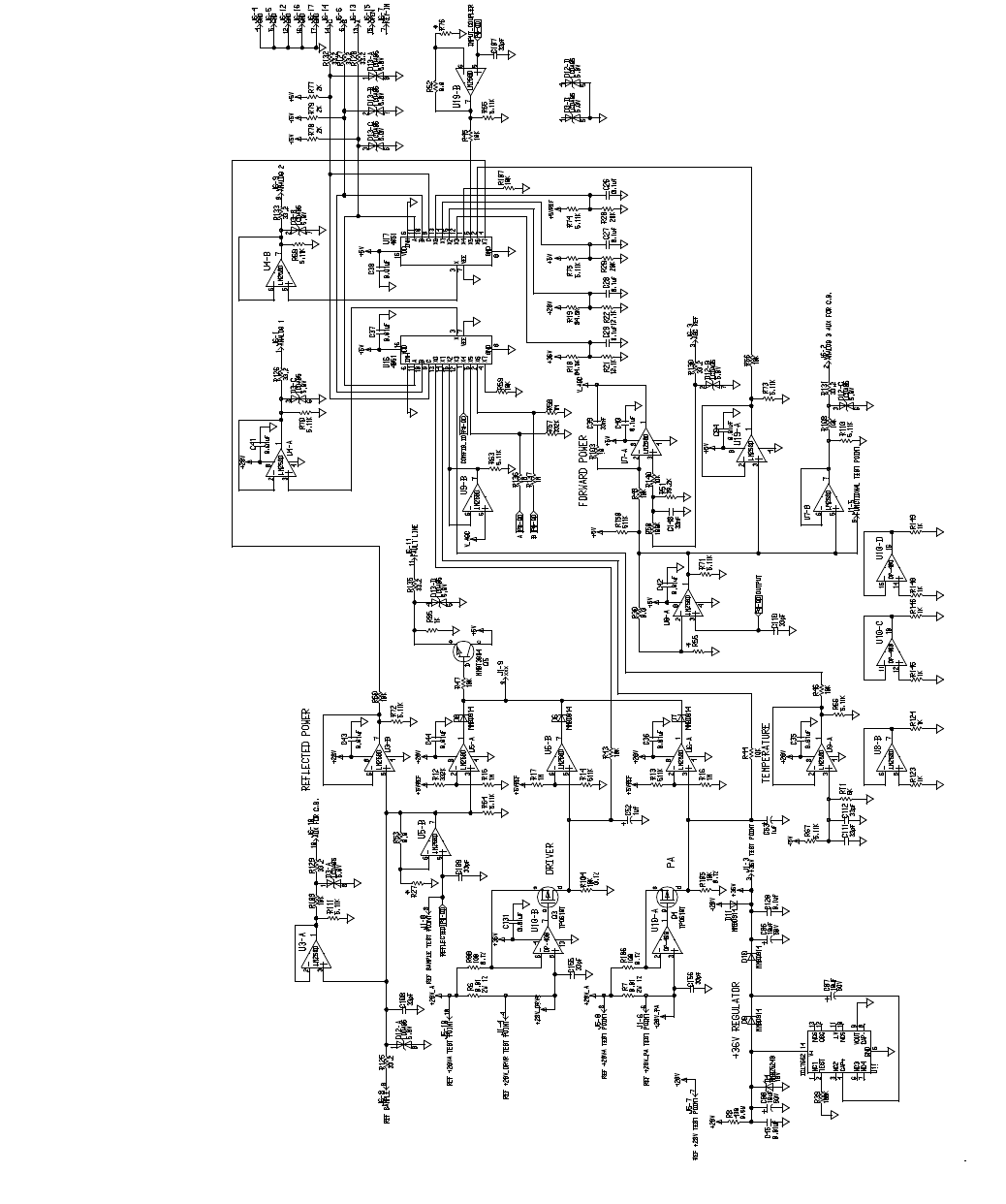
6.3 PA Board
The DSP exciter monitors currents, voltages, powers, and other valuable status information
from the power amplifier through the PA board. The two main functions of the PA board
are to channel information from the PA chassis to the exciter and to distribute dc power to
the exciter, R9000, receiver and C2000.
Most of the information passed to the exciter is in the form of voltages that represent
powers, currents, supply voltages and temperature. This information is multiplexed in the
PA board onto two analog lines that feed the exciter’s analog-to-digital converter (ADC).
The PA board also detects overcurrent and high reflected power conditions in the PA. Once
this condition is detected, the PA board pulls a PA fault line high initiating an interrupt in
the exciter. This interrupt causes the exciter to reduce power or shut the transmitter down
to protect it from damage.

Glenayre Document Number: 9110.01306 GL-T8200 1- to 25-Watt 900-MHz Power Amplifier
Rev. A: 03/23/99 THEORY OF OPERATION
25w82006
Print Date: 05/10/99 Copyright © 1999 Glenayre Page: 6-3
6.3.1 Input Voltage
dc power input Refer to Figure 6-2. The +28-volt supply voltage from the main power supply feeds the
distribution circuitry on the PA board through an Anderson power pole. The negative side
of the supply is grounded to the black (-) connection. The positive side of the supply goes
to the red (+) connection and on to the distribution circuitry on the PA board.
fuses The +28-volt supply is distributed throughout the PA board through current monitoring
circuits and fuses. The +28-volt supply voltage is also used in the metering circuitry. Refer
to fuse information in Table 4-4.
internal voltages The internal supply voltages described in Paragraph 6.3.2 are derived from the main
supply line. Refer to Table 6-1 for more information concerning the PA board regulators,
voltages, and test points.
6.3.2 Internally Generated Voltages
6.3.2.1 +36-Volt Internal Supply
The +36-volt supply is derived with a voltage doubling circuit. This supply has a very low
current since it only drives the current monitoring op-amps in the PA board. These op-amps
monitor the current of transistors Q1 and Q2 from the high side of the 28-volt supply, and
therefore require a supply higher voltage. The +36-volt supply can be monitored at J1-6
with reference to ground
6.3.2.2 +5-Volt Precision Reference Internal Supply
The +5-volt reference supply also supplies very little current and is used for fault detec-
tions, where the trip point is critical. The +5-volt reference supply can be monitored at J1-
4 with reference to ground.
6.3.2.3 +5-Volt Internal Supply
The +5-volt supply has to supply approximately 1 ampere at 5 volts to portions of the PA
board. Filtering is required to keep RF from getting onto the PA board circuitry. The +5-
volt supply can be monitored at J1-3 with reference to ground.
6.3.2.4 +28-Volt Supply
The +28-volt supply is monitored by the multiplexer 0 on the PA board. The +28-volt
supply can be monitored at TB1-1.
GL-T8200 1- to 25-Watt 900-MHz Power Amplifier Glenayre Document Number: 9110.01306
THEORY OF OPERATION Rev. A: 03/23/99
Page: 6-4 Copyright © 1999 Glenayre Print Date: 05/10/99
sheet1.plt
Figure 6-2 PA Board Functional Diagram
GL-T8200 1- to 25-Watt 900-MHz Power Amplifier Glenayre Document Number: 9110.01306
THEORY OF OPERATION Rev. A: 03/23/99
Page: 6-6 Copyright © 1999 Glenayre Print Date: 05/10/99
6.4 Exciter Interface
The physical interface is a 15-pin, filtered male connector on the exciter and the PA chassis.
15-pin connector J6 is mounted on the PA board.
More information concerning the DSP exciter interface connector pinout is given in
Paragraph 6.4.1. For information on setting the PA to expect the standard DSP exciter,
refer to Paragraph 4.2.1.
6.4.1 Exciter Interface Connector Pinout
Refer to Table 4-3. The interface connector pin numbers refer to the 15-pin exciter/PA
interface connector on the rear of the PA chassis and the DSP exciter.
6.4.1.1 Analog 1 Output
Pins 1 (+) of the D-sub 15-pin interface connector is the analog 1 output from multiplexer
0 on the PA board. The output voltage range is 0-5 volts for the + pin, the - pin is referenced
to PA ground. The analog value on the multiplexer output may be one of eight different
channels and is selected by the microcontroller through the multiplexor select lines 0-2.
6.4.1.2 Analog 3 Output
Pins 2 (+) of the D-sub 15-pin interface connector is the analog 3 output which goes to J6-
2 and is used for customer specials. The output voltage range is 0-5 volts for the (+) pin,
the (-) pin is referenced to PA ground. This analog output operation is the same as the
analog 0 output described above.
6.4.1.3 Mux Select Lines 0-2
Pins 13, 6, and 14 of the D-sub 15-pin interface connector are multiplex lines 0 through 2,
respectively. These input lines from the exciter are digital in nature and are used to select
the appropriate channel of the analog multiplexers on the PA board.
6.4.1.4 PA Fault Interrupt
Pin 11 of the D-sub 15-pin interface connector is the chassis fault-interrupt output line. This
output goes from LO to HI to indicate that a high VSWR or high-current condition has
occurred in the PA. This output is digital in nature and drives an interrupt input to the micro-
controller in the exciter. This output from the PA board is ORed with the other PA board
fault outputs; therefore only one line has to be active to indicate a fault.
6.5 Analog Readings Thresholds
Refer to Table 6-2.

Glenayre Document Number: 9110.01306 GL-T8200 1- to 25-Watt 900-MHz Power Amplifier
Rev. A: 03/23/99 THEORY OF OPERATION
25w82006
Print Date: 05/10/99 Copyright © 1999 Glenayre Page: 6-7
6.5.1 PA Board Currents
The currents monitored in the PA board have various upper limits, as shown in Table 6-2.
They are read on the VDT screen. When one or more of these thresholds is met, it causes
an interrupt to the microcontroller in the exciter, which then reduces output power until the
fault condition no longer exists or until shutdown occurs. As of this printing, no lower
current limit has been programmed.
6.5.2 PA Forward Power
The PA board forward and reflected samples are digitized and sent out the I20 interface.
The forward power reading from the PA board has a lower limit which is determined by the
forward power setting of the transmitter. This limit is based on efficiency and losses in the
PA. The lower limit is 1 watt. The upper limit for the forward power reading is 25 watts.
This does not cause an interrupt to the exciter, but if a reading exceeds this level, the exciter
shuts the transmitter down.
6.5.3 PA Reflected Power
The reflected power reading in the PA has a lower limit of 0 W, and an upper limit of 5 W
average power. When this limit is achieved, it initiates an interrupt to the microcontroller
in the exciter which reduces power until the fault goes away or until a shutdown condition
occurs.
6.5.4 PA Board RF Input Power
The input power to the PA has a lower limit of 200 mW. If the threshold is not reached, the
PA shuts down.
6.5.5 +28-Volt External Supply
The upper limit of the PA’s 28 volt supply is +29 volts, and the lower limit is +22 volts.
Excursions outside these limits are a fault state. The transmitter shuts down.
6.5.6 +36-Volt Internal Supply
The +36 volt supply to the current metering op-amps has a window of +33 volts and +39
volts. When these limits have been exceeded, it results in an alarm condition only, no power
reduction.

GL-T8200 1- to 25-Watt 900-MHz Power Amplifier Glenayre Document Number: 9110.01306
THEORY OF OPERATION Rev. A: 03/23/99
Page: 6-8 Copyright © 1999 Glenayre Print Date: 05/10/99
6.5.7 +5-Volt Internal Supplies
Both of the +5-volt supplies in the PA have an alarm window of +5.5 and +4.5 volts.
Exceeding either parameter results in an alarm condition only.
6.5.8 Temperature
The ambient temperature in the PA has an upper limit of +85 C. If this limit is exceeded,
the transmitter shuts down.
Table 6-2 Metered Parameter Thresholds
analog reading
upper
threshold lower
threshold
PA PA
total forward power (W) 25 1
total reflected power (W) 5 0
PA current Q1 1.6 none
PA current Q2 3.3 none
+36 Vdc 39 33
+28 Vdc 29 22
+5 Vdc 5.5 4.5
temperature 80o (alarm)
85o (fault) -30o

Glenayre Document Number: 9110.01306 GL-T8200 1- to 25-Watt 900-MHz Power Amplifier
Rev. A: 03/23/99 MAINTENANCE
25w82007
Print Date: 03/26/99 Copyright © 1999 Glenayre Page: 7-1
7 MAINTENANCE
If the PA becomes faulty, get a replacement from Glenayre customer service.
7.1 Cleaning
The PA chassis should be kept clean and free of dust. Dust and dirt can reduce the cooling
efficiency of the PA which can lead to module failure. Dirt on the printed circuit boards can
also lead to other types of failures. Most dust and dirt can be removed with a vacuum
cleaner. Do not use air pressure to blow dust and dirt from the module, because it allows
dust to resettle on other equipment which may have already been cleaned.
7.2 Power Calibration
The complete power calibration was done with precise measuring equipment at the factory;
the accuracy exceeds that of field-quality test equipment. Refer to the DSP exciter user
manual for details. The transmitter is adjusted to the desired power via the video display
terminal.
GL-T8200 1- to 25-Watt 900-MHz Power Amplifier Glenayre Document Number: 9110.01306
MAINTENANCE Rev. A: 03/23/99
Page: 7-2 Copyright © 1999 Glenayre Print Date: 03/26/99

Glenayre Document Number: 9110.01306 GL-T8200 1- to 25-Watt 900-MHz Power Amplifier
Rev. A: 03/23/99 CHECKOUT AND TROUBLESHOOTING
25w82008
Print Date: 05/10/99 Copyright © 1999 Glenayre Page: 8-1
8 CHECKOUT AND TROUBLESHOOTING
8.1 Introduction
Checkout procedures can be performed at any time to verify that the power amplifier (and
transmitter) is functioning properly. After the checkout procedures are successfully
completed, the site can be returned to normal service. Pursue any troubleshooting
procedure provided or referenced, which is a direct result of a failed checkout procedure
before trying to complete the checkout procedure.
The following procedures presume that the installation and setup procedures in section 4 of
this manual have already been successfully completed. Refer to the DSP exciter VDT user
manual for more checkout procedures.
8.2 Checkout Procedures
8.2.1 VDT Power-Up Verification
Once powered, verify that the VDT is powered. Check list below:
• the VDT should have a cursor displayed and blinking
• or the VDT should have an instructional prompt displayed
• or the VDT should have an auto-loaded program running.
8.2.2 Dc Voltage Verification
Once powered, verify that the fan is operating. The fan is located on the rear of the PA. Also
insure that air flow is not obstructed inside or outside of the transmitter cabinet, around the
cabinet vents, and in the heat sink cooling fins of the PA.
8.3 Troubleshooting Procedures
Connect the VDT to the VT-100 connector on the front panel of the DSP exciter. Check the
power amplifier parameters using the VDT, refer to the DSP exciter VDT user manual for
assistance in using the VDT menus for troubleshooting.
8.3.1 Parameter Readings at Time of Fault
When the DSP exciter receives a fault indication from the transmitter or exciter, it records
all of the transmitter parameters at that instant. This is a valuable source of PA trouble-
shooting data and should always be checked when transmitter problems occur. Connect the
VDT to the VT-100 connector on the front panel of the exciter to access the transmitter fault
information. Refer to the DSP exciter VDT user manual for assistance in reading the trans-
mitter faults. Check the transmitter fault parameters against the normal transmitter
operating parameters. The normal transmitter operating parameters can be obtained from
the factory transmitter test data sheets; or (if available) from the transmitter parameters log
mentioned in sections 4 and 7 of this manual.

GL-T8200 1- to 25-Watt 900-MHz Power Amplifier Glenayre Document Number: 9110.01306
CHECKOUT AND TROUBLESHOOTING Rev. A: 03/23/99
Page: 8-2 Copyright © 1999 Glenayre Print Date: 05/10/99
8.3.2 GL-C2000 Transmitter Controller Alarms
Another valuable source of PA troubleshooting data is the GL-C2000 alarm history. It is
accessed by connecting the VDT to the VT-100 connector on the front panel of the GL-
C2000 transmitter controller. Consult the GL-C2000 user manual for assistance in
accessing the controller alarm history.
If the GL-C2000 has a telephone line connected to its modem output, its alarm history can
be accessed remotely through the use of the Glenayre GL-N2000 console, or with a
computer which is running a communication program with VT-100 emulation and has a
2400-baud modem.
The GL-N2000 console equipped with version 3.5 or later software can also perform an
over-the-air connection if telephone lines are not connected to the GL-C2000 controller.
8.3.3 Operational Checks
If the transmitter is operational, valuable troubleshooting information can be obtained by
comparing the present transmitter operating parameters, obtained through the exciter VDT
connection, to the parameters from the factory transmitter data sheets; or (if available) from
the transmitter parameters log.
8.3.4 Power Amplifier Current Measurement
Refer to Table 8-1, PA Board Current. The PA board has provisions to measure the current
flow of the first and second stage.
Table 8-1 PA Board Current
PA board function transistor current measured
first stage measure Q1 current
second stage measures Q2 current

Glenayre Document Number: 9110.01306 GL-T8200 1- to 25-Watt 900-MHz Power Amplifier
Rev. A: 03/23/99 REMOVAL AND REINSTALLATION
25w82009
Print Date: 03/26/99 Copyright © 1999 Glenayre Page: 9-1
9 REMOVAL AND REINSTALLATION
Caution
When fastening dc connectors, be certain that the
plug is centered directly on its corresponding jack
and that the polarity is correct. Do not make dc
connections while power is applied to the chassis.
The PA is secured to the rails by eight screws.
9.1 PA
9.1.1 Removal
Note
Before removing the PA as a result of fault isolation, be certain that the
fault is with it. The exciter and interconnecting wiring are essential to
proper operation of the power amplifier.
1. Loosen the eight screws on the front of the PA.
2. Disconnect I20, dc power in, dc power out, RF in, and RF out from the back of the
PA.
3. Pull PA out of rack until it is completely out.
9.1.2 Reinstallation
1. Place PA into location in rack.
2. Put in eight screws and lightly fasten.
3. Attach I20, dc power in, dc power out, RF in and RF out to the back of the PA.
4. Tighten screws.
This procedure is complete. Check out the transmitter to see that it functions properly.
GL-T8200 1- to 25-Watt 900-MHz Power Amplifier Glenayre Document Number: 9110.01306
REMOVAL AND REINSTALLATION Rev. A: 03/23/99
Page: 9-2 Copyright © 1999 Glenayre Print Date: 03/26/99
Print Date: 03/24/99 Copyright © 1999 Glenayre
GL-T8200 1- to 25-Watt 900-MHz Transmitter System Rev. A: 03/24/99
Specifications subject to change without notice
Copyright © 1999 Glenayre
All rights reserved. No part of this work may be reproduced or copied in any form or by
any means—graphic, electronic, or mechanical, including photocopying, recording,
taping, or information-retrieval system—without written permission of Glenayre.
GL-T8200
1- to 25-Watt 900-MHz Transmitter System
USER MANUAL
PN 9110.01305
REV A
GL-T8200 1- to 25-Watt 900-MHz Transmitter System Glenayre Document Number: 9110.01305
Document Change Record Rev. A: 03/24/99
Copyright © 1999 Glenayre Print Date: 03/24/99
Document Change Record
Revision: A
Date: 03/24/99
Changes: none; original

Glenayre Document Number: 9110.01305 GL-T8200 1- to 25-Watt 900-MHz Transmitter System
Rev. A: 03/24/99 Table of Contents
8200sys1.toc
Print Date: 04/14/99 Copyright © 1999 Glenayre Page: -i
Table of Contents
1 GENERAL. . . . . . . . . . . . . . . . . . . . . . . . . . . . . . . . . . . . . 1-1
1.1 Manual Scope . . . . . . . . . . . . . . . . . . . . . . . . 1-1
1.2 Applicable Documents. . . . . . . . . . . . . . . . . . . . . 1-1
1.3 Manual Sections . . . . . . . . . . . . . . . . . . . . . . . 1-1
1.4 About Glenayre . . . . . . . . . . . . . . . . . . . . . . . 1-2
1.4.1 Product Warranty Information . . . . . . . . . . . . . . . . . . .1-3
1.4.2 Service Warranty Information . . . . . . . . . . . . . . . . . . .1-3
1.5 Regulatory-Authority Compliance . . . . . . . . . . . . . . . . 1-3
1.5.1 FCC . . . . . . . . . . . . . . . . . . . . . . . . . . . . . . . . .1-3
1.5.2 Industry Canada. . . . . . . . . . . . . . . . . . . . . . . . . . .1-3
1.5.3 Other . . . . . . . . . . . . . . . . . . . . . . . . . . . . . . . .1-3
2 SPECIFICATIONS . . . . . . . . . . . . . . . . . . . . . . . . . . . . . . . . 2-1
3 +DESCRIPTION . . . . . . . . . . . . . . . . . . . . . . . . . . . . . . . . . 3-1
3.1 Physical Description. . . . . . . . . . . . . . . . . . . . . . 3-1
3.1.1 Mounting Provisions . . . . . . . . . . . . . . . . . . . . . . . .3-1
3.1.2 Exciter. . . . . . . . . . . . . . . . . . . . . . . . . . . . . . . .3-1
3.1.3 Power Amplifier (PA). . . . . . . . . . . . . . . . . . . . . . . .3-2
3.1.4 Power Supply . . . . . . . . . . . . . . . . . . . . . . . . . . . .3-2
3.1.5 Video Display Terminal (VDT). . . . . . . . . . . . . . . . . . .3-2
3.2 Simplified Paging-Site Functional Description . . . . . . . . . . . 3-2
3.2.1 Paging Site . . . . . . . . . . . . . . . . . . . . . . . . . . . . .3-2
3.2.2 Link Equipment and Transmitter Controller . . . . . . . . . . . .3-2
3.2.3 Paging Transmitter . . . . . . . . . . . . . . . . . . . . . . . . .3-4
3.2.4 Video Display Terminal. . . . . . . . . . . . . . . . . . . . . . .3-4
3.2.5 Ac Power Supply . . . . . . . . . . . . . . . . . . . . . . . . . .3-4
3.3 Site Signal Flows . . . . . . . . . . . . . . . . . . . . . . . 3-4
3.3.1 Site RF-Signal Flow. . . . . . . . . . . . . . . . . . . . . . . . .3-4
3.3.2 Site Audio/Modulation-Signal Flow . . . . . . . . . . . . . . . .3-5
3.3.3 Simplified Block-Diagram Description. . . . . . . . . . . . . . .3-6
3.3.4 Site Control-Signal Flow . . . . . . . . . . . . . . . . . . . . . .3-7
3.3.5 Status-Signal Flow . . . . . . . . . . . . . . . . . . . . . . . . .3-7
4 INSTALLATION AND SETUP . . . . . . . . . . . . . . . . . . . . . . . . . 4-1
4.1 Site Checks . . . . . . . . . . . . . . . . . . . . . . . . . 4-1
4.1.1 Transmitter Environment . . . . . . . . . . . . . . . . . . . . . .4-1
4.1.2 Inspection . . . . . . . . . . . . . . . . . . . . . . . . . . . . . .4-1
GL-T8200 1- to 25-Watt 900-MHz Transmitter System Glenayre Document Number: 9110.01305
Table of Contents Rev. A: 03/24/99
Page: -ii Copyright © 1999 Glenayre Print Date: 04/14/99
4.1.3 Primary Power Requirement . . . . . . . . . . . . . . . . . . . . 4-1
4.2 Installation . . . . . . . . . . . . . . . . . . . . . . . . . 4-2
4.2.1 Tools and Equipment Required. . . . . . . . . . . . . . . . . . . 4-2
4.2.2 Rack Positioning . . . . . . . . . . . . . . . . . . . . . . . . . . 4-2
4.2.3 Rack Grounding . . . . . . . . . . . . . . . . . . . . . . . . . . 4-2
4.2.4 Positioning within the Rack . . . . . . . . . . . . . . . . . . . . 4-3
4.2.5 Equipment Cabling . . . . . . . . . . . . . . . . . . . . . . . . . 4-3
4.3 Setup . . . . . . . . . . . . . . . . . . . . . . . . . . . 4-4
4.4 Ultimate Disposition . . . . . . . . . . . . . . . . . . . . . 4-4
5 OPERATION . . . . . . . . . . . . . . . . . . . . . . . . . . . . . . . . . . . 5-1
5.1 Controls and Indicators . . . . . . . . . . . . . . . . . . . . 5-1
5.2 Operation . . . . . . . . . . . . . . . . . . . . . . . . . 5-1
5.2.1 Turn Transmitter On and Off . . . . . . . . . . . . . . . . . . . . 5-1
5.2.2 Turn Fans On and Off . . . . . . . . . . . . . . . . . . . . . . . 5-1
5.2.3 Key and Unkey PA . . . . . . . . . . . . . . . . . . . . . . . . . 5-1
6 THEORY OF OPERATION. . . . . . . . . . . . . . . . . . . . . . . . . . . 6-1
6.1 Cabinet Power Distribution . . . . . . . . . . . . . . . . . . 6-1
6.1.1 Ac Power Input . . . . . . . . . . . . . . . . . . . . . . . . . . . 6-1
6.1.2 Dc Power Distribution . . . . . . . . . . . . . . . . . . . . . . . 6-1
6.2 Cabinet Signal Distribution . . . . . . . . . . . . . . . . . . 6-1
6.2.1 Control, Data, and Modulation Paths. . . . . . . . . . . . . . . . 6-1
6.2.2 Alarm Reporting . . . . . . . . . . . . . . . . . . . . . . . . . . 6-1
7 MAINTENANCE . . . . . . . . . . . . . . . . . . . . . . . . . . . . . . . . . 7-1
7.1 Introduction . . . . . . . . . . . . . . . . . . . . . . . . 7-1
7.2 Maintenance Procedures. . . . . . . . . . . . . . . . . . . . 7-1
7.2.1 PA Current Check . . . . . . . . . . . . . . . . . . . . . . . . . 7-1
7.2.2 Dc Ripple Check . . . . . . . . . . . . . . . . . . . . . . . . . . 7-1
8 CHECKOUT AND TROUBLESHOOTING . . . . . . . . . . . . . . . . . . 8-1
8.1 Preparation for Checkout Procedures. . . . . . . . . . . . . . . 8-1
8.1.1 Dc-Voltage Verification . . . . . . . . . . . . . . . . . . . . . . 8-1
8.1.2 VDT Power-up Verification . . . . . . . . . . . . . . . . . . . . 8-1
8.1.3 Cooling-Fan Check . . . . . . . . . . . . . . . . . . . . . . . . . 8-1
8.2 Operational Verification. . . . . . . . . . . . . . . . . . . . 8-1
8.2.1 RF Power and Antenna . . . . . . . . . . . . . . . . . . . . . . . 8-2
8.2.2 Paging. . . . . . . . . . . . . . . . . . . . . . . . . . . . . . . . 8-2
8.3 Field Replacement of Assemblies . . . . . . . . . . . . . . . . 8-2

Glenayre Document Number: 9110.01305 GL-T8200 1- to 25-Watt 900-MHz Transmitter System
Rev. A: 03/24/99 Table of Contents
8200sys1.toc
Print Date: 04/14/99 Copyright © 1999 Glenayre Page: -iii
9 REMOVAL AND REINSTALLATION. . . . . . . . . . . . . . . . . . . . . 9-1
9.1 Power Supply . . . . . . . . . . . . . . . . . . . . . . . . 9-1
9.2 Exciter Removal and Reinstallation. . . . . . . . . . . . . . . . 9-1
9.3 PA Removal and Reinstallation . . . . . . . . . . . . . . . . . 9-2
GL-T8200 1- to 25-Watt 900-MHz Transmitter System Glenayre Document Number: 9110.01305
Table of Contents Rev. A: 03/24/99
Page: -iv Copyright © 1999 Glenayre Print Date: 04/14/99

Glenayre Document Number: 9110.01305 GL-T8200 1- to 25-Watt 900-MHz Transmitter System
Rev. A: 03/24/99 List of Figures
8200sys1.lof
Print Date: 04/14/99 Copyright © 1999 Glenayre Page: -v
List of Figures
Figure 3-1 Transmitter Front View . . . . . . . . . . . . . . . . . . . . . . . . . . 3-3
Figure 3-2 Transmitter Simplified Block Diagram . . . . . . . . . . . . . . . . . . 3-6
Figure 4-1 Rear View Showing Dc and Signal Connections . . . . . . . . . . . . . 4-5
GL-T8200 1- to 25-Watt 900-MHz Transmitter System Glenayre Document Number: 9110.01305
List of Figures Rev. A: 03/24/99
Page: -vi Copyright © 1999 Glenayre Print Date: 04/14/99

Glenayre Document Number: 9110.01305 GL-T8200 1- to 25-Watt 900-MHz Transmitter System
Rev. A: 03/24/99 List of Tables
8200sys1.lot
Print Date: 04/14/99 Copyright © 1999 Glenayre Page: -vii
List of Tables
Table 1-1 Applicable Documents . . . . . . . . . . . . . . . . . . . . . . . . . . 1-1
Table 1-2 Manual Sections . . . . . . . . . . . . . . . . . . . . . . . . . . . . . 1-2
Table 2-1 Specifications . . . . . . . . . . . . . . . . . . . . . . . . . . . . . . . 2-1
Table 3-1 Site Equipment List . . . . . . . . . . . . . . . . . . . . . . . . . . . . 3-1
Table 4-1 Required Tools and Equipment. . . . . . . . . . . . . . . . . . . . . . 4-2
GL-T8200 1- to 25-Watt 900-MHz Transmitter System Glenayre Document Number: 9110.01305
List of Tables Rev. A: 03/24/99
Page: -viii Copyright © 1999 Glenayre Print Date: 04/14/99

Glenayre Document Number: 9110.01305 GL-T8200 1- to 25-Watt 900-MHz Transmitter System
Rev. A: 03/24/99 GENERAL
8200sys1
Print Date: 05/10/99 Copyright © 1999 Glenayre Page: 1-1
1GENERAL
1.1 Manual Scope
This manual provides information for the following transmitter:
• 1 to 25-watt, 900-MHz transmitter, model GL-T8200.
1.2 Applicable Documents
This manual is incomplete without additional manuals. Refer to Table 1-1 for a list of
applicable documents, their part numbers, and a brief description of each.
1.3 Manual Sections
Refer to Table 1-2. This table lists the sections in this manual, and provides a brief descrip-
tion of the content of each section.
Table 1-1 Applicable Documents
document part number description
9100.XXXXX 9100.XXXXX assembled GL-T8200 manual. Requestors
should ask for option manuals which match
their configuration.
GL-T8200 system manu-
al 9110.001305 this document
DSP VDT manual 9110.00259 describes DSP exciter software installed in
exciter
DSP exciter User Manual 9110.01021 describes DSP exciter hardware equipment
in transmitter
GL-C2000 User Manual 9110.01248 describes GL-C2000 controller hardware
and software
GL-T8200 power ampli-
fier manual 9110.001306 describes 1 to 25 watt, 900-MHz power
amplifier
power supply manual 9110.00622 describes GL2728 power supply equipment

GL-T8200 1- to 25-Watt 900-MHz Transmitter System Glenayre Document Number: 9110.01305
GENERAL Rev. A: 03/24/99
Page: 1-2 Copyright © 1999 Glenayre Print Date: 05/10/99
1.4 About Glenayre
Questions regarding the equipment or this manual should be directed to:
U.S.A. CANADA
Glenayre Customer Service - RF Glenayre Customer Service - RF
One Glenayre Way 1450 Kootenay Street
Quincy, Illinois 62305-3726 Vancouver, B.C.V5K 4R1
Phone: (217) 223-3211 Phone: (604) 293-1611
Fax: (217) 221-6259 Fax: (604) 293-4301
UNITED KINGDOM SINGAPORE
Glenayre Electronics (UK) Ltd. Glenayre Electronics Pte Ltd.
Unit 22, Challenge House No. 8 Ang Mo Kio
Sherwood Drive Industrial Park 2
Bletchley, Milton Keynes, MK3 6JD 569500 Singapore
Phone: 44 (1908) 484800 Phone: 65 483-8787
Fax: 44 1908 484801 Fax: 65 483-9663
For additional Glenayre contacts, refer to
www.glenayre.com/corporate/contacts/default.asp .
Table 1-2 Manual Sections
section contents
1. General introduction and purpose of manual
2. Specifications significant system measurements; also see individual equip-
ment manuals
3. Description introduction and principle characteristics of the equipment
4. Installation & Setup initial installation and activation of the equipment
5. Operation operation of equipment
6. Theory of Operation detailed functional description of transmitter
7. Maintenance procedures to be performed on specific intervals to maintain
optimum performance of the equipment
8. Checkout and Trouble-
shooting verification of proper operation, correction to proper opera-
tion
9. Removal and Reinstal-
lation replacement procedures for assemblies which do not have
their own, separate equipment manuals

Glenayre Document Number: 9110.01305 GL-T8200 1- to 25-Watt 900-MHz Transmitter System
Rev. A: 03/24/99 GENERAL
8200sys1
Print Date: 05/10/99 Copyright © 1999 Glenayre Page: 1-3
1.4.1 Product Warranty Information
Glenayre warrants to the original purchaser that Glenayre products are free from defects in
material and workmanship for a period of twenty-four months from the original invoice
date, subject to the provisions herein. Glenayre will repair or replace at its option, FOB our
factory, free of charge within one year from the date of shipment, any component, assembly
or subassembly of our manufacture found to be defective under conditions of normal use.
The unit, if repaired, will be returned to its original specifications. Failures caused by unau-
thorized modifications, force majeure, lightning, physical, environmental, or electrical
damage including use with incompatible equipment are specifically excluded from this
warranty. Glenayre disclaims any and all liability for loss or other damage whether direct,
consequential or of any nature whatsoever, resulting from product failure.
This warranty is in lieu of all other warranties expressed or implied and covers only those
items manufactured by Glenayre. Equipment supplied by, but not manufactured by
Glenayre, is subject only to any warranty offered by the manufacturer of said equipment.
1.4.2 Service Warranty Information
Return of a defective item must be authorized by Glenayre prior to shipment. A Return
Authorization number can be obtained from Glenayre Customer Service. When requesting
a Return Authorization number, give the serial number of the unit. A description of the fault
should accompany the unit on its return and the RA number must be shown on labels
attached to the item(s). The cost of shipping to Glenayre is to be paid by the customer.
Shipping from Glenayre will be prepaid by the customer, and shipped via surface mail. If
express shipping is required, the unit will be shipped collect.
Any repair service performed by Glenayre under this limited warranty is warranted to be
free from defects in material or workmanship for ninety days from the date of repair. All
other terms of this limited warranty apply to the service warranty.
1.5 Regulatory-Authority Compliance
1.5.1 FCC
Refer to Table 2-1 for authorizations.
1.5.2 Industry Canada
Refer to Table 2-1 for authorizations.
1.5.3 Other
Refer to Table 2-1 for authorizations. Type approvals have been applied for in all major
markets. Refer to Paragraph for more information.
GL-T8200 1- to 25-Watt 900-MHz Transmitter System Glenayre Document Number: 9110.01305
GENERAL Rev. A: 03/24/99
Page: 1-4 Copyright © 1999 Glenayre Print Date: 05/10/99

Glenayre Document Number: 9110.01305 GL-T8200 1- to 25-Watt 900-MHz Transmitter System
Rev. A: 03/24/99 SPECIFICATIONS
8200sys2
Print Date: 05/10/99 Copyright © 1999 Glenayre Page: 2-1
2 SPECIFICATIONS
Table 2-1 contains transmitter and power supply specifications. The ac power supply is a
purchased item. Refer to the power supply manual, PN 9110.00622, for more specifica-
tions. Refer also to the exciter and PA manuals for detailed specifications. Test and
measurement equipment is, where possible, calibrated in accordance with standards estab-
lished by the National Institute of Standards and Technology (NIST).
Table 2-1 Specifications
characteristic
(unit of
measurement) condition, model specification
Electrical
RF output power
(W) continuous duty, at PA
RF output connector 1-25
Physical and Environmental
dimensions 16 RU in standard EIA
cabinet (can be re-
duced to 14 RU in non-
standard configura-
tions)
28 x 19 x 9 in (71 x 48 x 22 cm)
weight 50 lb (23 kg)
elevation continuous operation
at rated power to 10,000 ft (3050 m) (see temperature der-
ating factor)
temperature operating -30 to +60 degrees C
storage -30 to +70 degrees C
temperature derat-
ing factor above 5000 ft
(1525 m) 0.5 degrees C per 100 m
humidity operating, noncon-
densing 5 to 95%
Certification
country model identifier
USA GL-T8200 BFL-GL-T8200
Canada GL-T8200

GL-T8200 1- to 25-Watt 900-MHz Transmitter System Glenayre Document Number: 9110.01305
SPECIFICATIONS Rev. A: 03/24/99
Page: 2-2 Copyright © 1999 Glenayre Print Date: 05/10/99
other Contact Glenayre Sales for country-by-country type-approval infor-
mation
Electrical (power supply)
ac input voltage
(Vac) 195 to 265
ac input frequency
(Hz) 47 to 440
ac input current (A) 4 max at 195 Vac to 265 Vac
Table 2-1 Specifications (continued)
characteristic
(unit of
measurement) condition, model specification

Glenayre Document Number: 9110.01305 GL-T8200 1- to 25-Watt 900-MHz Transmitter System
Rev. A: 03/24/99 +DESCRIPTION
8200sys3
Print Date: 05/10/99 Copyright © 1999 Glenayre Page: 3-1
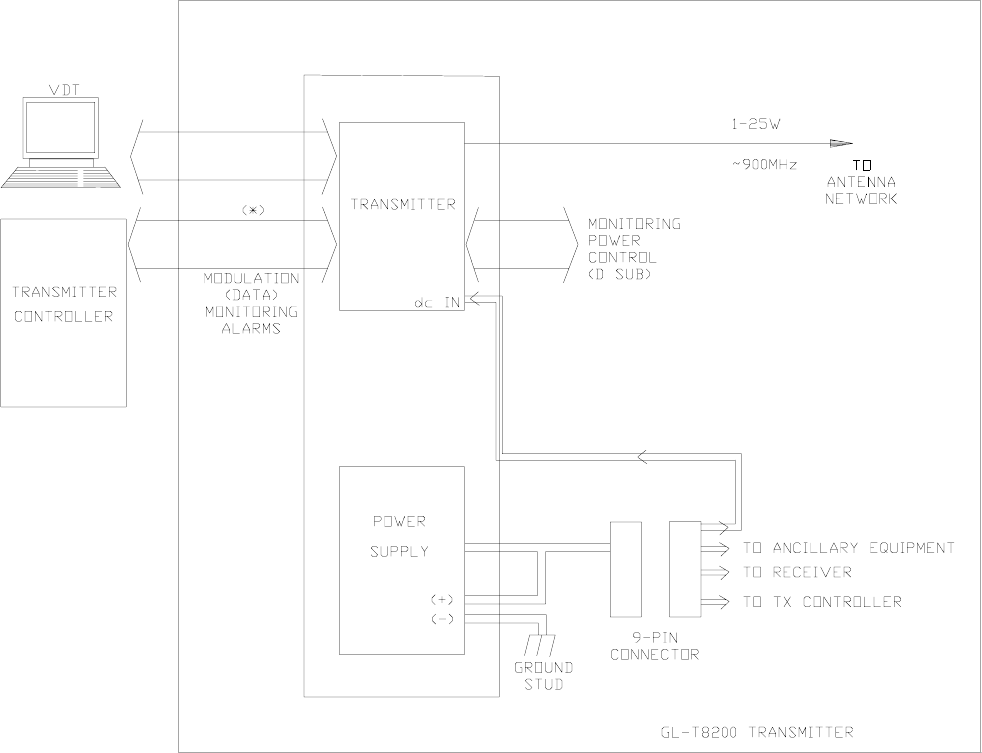
3 +DESCRIPTION
The purpose of the paging transmitter is to provide a modulated, high-level RF signal,
which sets off pagers within the coverage area of its associated antenna. The paging trans-
mitter receives modulation and control information from the transmitter controller, which
receives information from a control site. In a simulcasting environment, the control site
may feed several paging sites at once.
3.1 Physical Description
Figure 3-1 shows a front view of the PA chassis. Refer to the transmitter ID label on the
rear of the unit for identification purposes.
3.1.1 Mounting Provisions
3.1.1.1 Transmitter Controller
The transmitter controller, normally a GL-C2000, is mounted above the exciter and may be
packaged with blank panels.
3.1.2 Exciter
The exciter is one rack unit high. It is racked where shown and is held in place with four
machine screws. The top cover is removable for access to subassemblies, jumpers, and
adjustments contained in the unit. All but one of its connectors are on the back of the unit.
The front of this unit has a connector which allows the VDT to be connected to it.
Table 3-1 Site Equipment List
equipment part number function
power amplifier
GL-T8200 1000.02186 amplifies 900 MHz RF for broadcast
digital DSP
exciter with I20 option DSP EX/I20 OPT generates then modulates RF; controls PA
I/O activities, receives fault signals and
takes action based on status
GL-S2164 Receiver See receiver manual for
configurations and part
No.
receives data and commands from the
system controller
GL-C2000 (typical)
transmitter controller GL-C2000 controls paging transmitter activities;
performs I/O functions for paging site
power supply module ac switching power supply which converts
main power to dc voltage for the transmit-
ter
GL-T8200 1- to 25-Watt 900-MHz Transmitter System Glenayre Document Number: 9110.01305
+DESCRIPTION Rev. A: 03/24/99
Page: 3-2 Copyright © 1999 Glenayre Print Date: 05/10/99
3.1.3 Power Amplifier (PA)
The transmitter PA is mounted in the rack by screws which are inserted into the angle
brackets on either side of the chassis. Access to PA fuses is gained from the front; access to
the fan and I/O connections is from the rear.
A chassis-mounted fan draws air across the PA heat sink and out the back.
Most exciter and PA fault isolations can be performed with the units mounted in the rack.
It is not recommended to troubleshoot the PA if is is defective. A defective PA should be
sent back to Glenayre.
3.1.4 Power Supply
The power supply is contained in a separate chassis which is mounted separately from the
transmitter, normally as the lowest assembly in the rack. The power supply used is an ac
switching power supply which converts main power to dc voltage for the transmitter. Refer
to power supply manuals for details.
3.1.5 Video Display Terminal (VDT)
A video display terminal (VDT) is not part of the racked-up equipment; instead, it is a piece
of test equipment which the user brings to the site when setup, maintenance, or trouble-
shooting is necessary; or it is used as a monitoring device. Refer to the VDT manual for
details, including cable requirements.
3.2 Simplified Paging-Site Functional Description
3.2.1 Paging Site
The following paragraphs provide a block diagram-level functional description of a typical
paging site.
Refer to Figure 3-2. This figure shows basic signal flows between the various paging site
equipment pieces. The communications device which the transmitter uses in order to
communicate with the control site is not shown and may vary from application to
application.
3.2.2 Link Equipment and Transmitter Controller
A link receiver, satellite receiver, microwave drop, telephone link, or other similar device
is used for communication between the transmitter controller and the control site. The
particular device depends on the application.
The transmitter controller is typically a model GL-C2000. There are various ways of inter-
facing the transmitter controller to the I/O portions of the exciter. Refer to the transmitter
controller manual and the exciter manual for details.

Glenayre Document Number: 9110.01305 GL-T8200 1- to 25-Watt 900-MHz Transmitter System
Rev. A: 03/24/99 +DESCRIPTION
8200sys3
Print Date: 05/10/99 Copyright © 1999 Glenayre Page: 3-3
Figure 3-1 Transmitter Front View
GL-T8200 1- to 25-Watt 900-MHz Transmitter System Glenayre Document Number: 9110.01305
+DESCRIPTION Rev. A: 03/24/99
Page: 3-4 Copyright © 1999 Glenayre Print Date: 05/10/99
3.2.3 Paging Transmitter
The paging transmitter converts the digital signal from the transmitter controller into
modulated and amplified RF power.
Operation is in response to commands from the transmitter controller via the DSP exciter.
The transmitter monitors its functions and reports its status to the VDT and the GL-C2000
via the exciter. The transmitter controller permits the transmitter to be controlled and
monitored from a remote location. Local control and monitoring are performed through a
VT-100 video deplay terminal (VDT).
The DSP exciter combines functions of an RF exciter and a PA controller. The exciter
generates modulation using digital signal processing (DSP) to achieve accurate, stable
modulation that does not vary with time or temperature. The PA-control section monitors
transmitter status signals in the form of fault logic and voltage samples. The microprocessor
in the exciter reports PA status to the transmitter controller, VDT, and the exciter front
panel. If a malfunction occurs, the transmitter enters a reduced operating condition,
depending on the seriousness of the fault. PA control and status monitoring are performed
by the microprocessor, which consolidates control logic from the transmitter controller or
the locally operated VDT. Both the exciter and transmitter controller receive continuous
status reports from the microprocessor. The exciter is the control and status-monitoring
interface between the transmitter and the user.
The DSP exciter provides up to 400 milliwatts of RF drive.
A power-reference signal from the PA is fed back to the exciter, via the PA board, to allow
control and monitoring of output power. The exciter-supplied control voltage functions as
AGC control for the PA.
3.2.4 Video Display Terminal
The VDT, though not part of the transmitter, is required for setup, local control, and local
monitoring of the transmitter. The VDT can be any laptop or desktop terminal with a VT-
100 type program. The VDT interfaces the transmitter through the connector on the front
of the exciter. The VDT software is menu-driven.
3.2.5 Ac Power Supply
Refer to Figure 3-1. The switching power supply is mounted below the PA. The power
supply is two rack units high. The front panel contains a dc power on indicator.
3.3 Site Signal Flows
3.3.1 Site RF-Signal Flow
The on-frequency carrier is created by the VCO circuitry in the DSP exciter. It is then
modulated with paging information, amplified, and sent to the PA via connector J3 on the
back of the DSP exciter. Through coaxial cable, the carrier goes to the back of the PA,
where it is further amplified to a preset level under control of a microprocessor within the
exciter. The amplified carrier is cabled from the PA output to a low-pass filter and a triple

Glenayre Document Number: 9110.01305 GL-T8200 1- to 25-Watt 900-MHz Transmitter System
Rev. A: 03/24/99 +DESCRIPTION
8200sys3
Print Date: 05/10/99 Copyright © 1999 Glenayre Page: 3-5
isolator and then to a cabinet-mounted lightning protector/connector for connection to the
antenna system. Note that some installations have a ten-MHz reference signal cabled from
the transmitter controller to connector J8 on the back of the DSP exciter.
3.3.2 Site Audio/Modulation-Signal Flow
Modulation information arrives at the site either through a link receiver or by wireline. The
digital signal is first routed through the transmitter controller, which checks for and
responds to appropriate embedded commands. Paging information is supplied to the
exciter. The exciter modulates this signal using digital signal processing, then up-converts
this modulated signal to final output frequency. This modulated RF from the exciter is
supplied to the PA, which amplifies the signal to the RF output level. This modulated,
amplified RF from the PA is supplied to an antenna network for transmission.
GL-T8200 1- to 25-Watt 900-MHz Transmitter System Glenayre Document Number: 9110.01305
+DESCRIPTION Rev. A: 03/24/99
Page: 3-6 Copyright © 1999 Glenayre Print Date: 05/10/99
3.3.3 Simplified Block-Diagram Description
Refer to Figure 3-2. The interface between the transmitter and the transmitter controller is
the I20 interface. Refer to the exciter manual for details.
Figure 3-2 Transmitter Simplified Block Diagram

Glenayre Document Number: 9110.01305 GL-T8200 1- to 25-Watt 900-MHz Transmitter System
Rev. A: 03/24/99 +DESCRIPTION
8200sys3
Print Date: 05/10/99 Copyright © 1999 Glenayre Page: 3-7
3.3.4 Site Control-Signal Flow
Transmitter paging-site control is done two ways:
• remotely (normally operation), and
• locally.
In either case, the paging transmitter is keyed when the transmitter controller commands it,
via the DSP exciter, to key.
Control functions are shared by the transmitter controller and the DSP exciter, which
controls the power amplifier. The DSP exciter also controls the power amplifier locally by
responding to commands from the VDT.
Control signals enter and exit the paging site via the transmitter controller, which has
overall control of the paging site. The transmitter controller is part of the larger paging
control system even though it is racked with paging-site equipment. The transmitter
controller has control functions which include these:
• transmitter alarm-gathering
• transmitter-alarm dispatching
• simulcast-parameter implementation
• remote control.
Remote control of the paging site is done through commands being sent to the transmitter
controller from the external paging control system.
Control commands originating from a remote site are supplied to the exciter through the
controlling device. Control and setup commands may be applied to the exciter locally
through the VDT. A microprocessor within the exciter interprets each command and
responds by performing the appropriate function.
3.3.5 Status-Signal Flow
The exciter monitors transmitter status signal in the form of fault logic and voltage samples.
The microprocessor within the exciter reports transmitter status to the controlling device,
VDT, and the exciter front panel. If a transmitter malfunction occurs, a reduced operating
condition is entered, depending on the seriousness of the fault.
GL-T8200 1- to 25-Watt 900-MHz Transmitter System Glenayre Document Number: 9110.01305
+DESCRIPTION Rev. A: 03/24/99
Page: 3-8 Copyright © 1999 Glenayre Print Date: 05/10/99

Glenayre Document Number: 9110.01305 GL-T8200 1- to 25-Watt 900-MHz Transmitter System
Rev. A: 03/24/99 INSTALLATION AND SETUP
8200sys4
Print Date: 05/10/99 Copyright © 1999 Glenayre Page: 4-1
4 INSTALLATION AND SETUP
4.1 Site Checks
4.1.1 Transmitter Environment
The transmitter environment should be clean and well ventilated. Additionally, the temper-
ature inside the transmitter room should be maintained within the equipment specifications.
Refer to Table 4-2. The lower temperature limit is generally less of a problem due to the
heat produced by the equipment during operation, but it can become a problem in the colder
months of the year. The upper temperature limit is often a problem, especially in the
summer months. In accordance with local building codes and the permission of the building
owners, the advice of local heating and air conditioning professionals is recommended
prior to installation.
4.1.2 Inspection
Inspect the equipment to be certain that the shipment is complete. Compare items received
to the packing list. The packing list shows two portions of the equipment and options
specified on the sales order: the portion presently being shipped, and the portion still on
back order. It does not report the portion of the sales order that has already been shipped.
Report shipping loss or damage to carrier within 15 days of receipt. Remove any packing
material from the rack and check each assembly. Pay particular attention to the power
amplifier modules and power supply; check them closely and remove any foreign material
in the chassis or air cooling passages. Be certain to disconnect primary power from the
power supply before removing any equipment covers
4.1.3 Primary Power Requirement
The primary power source must be capable of delivering adequate power to the equipment.
Refer to the power supply manual. Electrical connections made to this equipment must be
made in accordance with local electrical codes.
• A switching power supply which operates in 115-Vac range and 230-Vac range. Refer to
power supply manual for specifications.
• Dc-to-dc converters may be used in some configurations.
The wire used to deliver the primary power must be large enough to safely carry the
required current. If the run of wire is too long, a larger size wire must be used to prevent
excessive voltage drop.

GL-T8200 1- to 25-Watt 900-MHz Transmitter System Glenayre Document Number: 9110.01305
INSTALLATION AND SETUP Rev. A: 03/24/99
Page: 4-2 Copyright © 1999 Glenayre Print Date: 05/10/99
4.2 Installation
Refer to Figure 4-1, for general information.
4.2.1 Tools and Equipment Required
Refer to Table 4-1. Equipment listed by brand name may be substituted with equivalent.
For installation, only common hand tools are necessary if at all, since installation is usually
completed at the factory.
4.2.2 Rack Positioning
Cooling and cabling restraints require that equipment pieces be racked so that there is
adequate ventilation for exhaust air. The front and back of the rack should have at least ten
inches of free space. The cabinet should be placed as close as possible to the transmitting
antenna, and to the primary power source as a secondary consideration. To gain reasonable
access to the back, 30 inches (75 cm) of free space should be allowed..
Caution
Never place the rack where moisture, steam,
condensation, or standing water, can come in
contact with it. The host room may need to be air
conditioned or additionally ventilated to remove
excess heat generated by this equipment.
4.2.3 Rack Grounding
The rack cabinet must be connected to a reliable earth ground. Connect the earth ground
point to the ground stud provided in the bottom of the cabinet; use four gauge or larger
copper conductor.
Table 4-1 Required Tools and Equipment
nut driver - 5/16 in (7.9 mm)
screw driver - #2 flat blade and # 3 flat blade
screw driver - #2 Phillips and #3 Phillips
Bird 4421 RF power meter
Bird 8327 dummy load
barrel connector - type-N
cable - 1 M long (max) with type-N ends
Fluke 77 DVM

Glenayre Document Number: 9110.01305 GL-T8200 1- to 25-Watt 900-MHz Transmitter System
Rev. A: 03/24/99 INSTALLATION AND SETUP
8200sys4
Print Date: 05/10/99 Copyright © 1999 Glenayre Page: 4-3
4.2.4 Positioning within the Rack
When it is used in a normal, one-transmitter-per-cabinet rackup, the transmitter should be
placed just above the power supply.
The transmitter is normally shipped already installed in a cabinet. To remove or reinstall
the transmitter, refer to Section 9.
DANGER
Rotating fan blades are a hazard to maintenance
personnel who access equipment from the rear.
4.2.5 Equipment Cabling
4.2.5.1 Ac and Dc Connections
Refer to Figure 4-1. Be certain that the site-environmental requirement for available ac
power has been met. A grommeted hole in the cabinet is recommended for ac power input
cable. The ac input is fused at the back of the power supply. Generally, all ac connections
internal to the rack are made at the factory and should not need to be modified. The high-
current positive supply and negative return to the PA are between power-supply DC
OUTPUT and the large jacks in the middle of the PA (as viewed from the rear). The PA
board has fusing which connects to the transmitter controller, DSP exciter, receiver, or any
other equipment.
4.2.5.2 Dc-Only Sites
This option is available. Some installations do not use ac input power. If the transmitter is
not racked and wired at the factory, be sure to connect as shown in the documentation
supplied with the retrofit option.
4.2.5.3 Signal Connections
Refer to Figure 4-2. Generally, all control and signal connections internal to the rack are
made at the factory and should not need to be modified.
antenna-receiver If a receiver is used, refer to the receiver manual for details.
receiver-transmitter controller A cable runs from the rear of the receiver to the transmitter controller. Refer to the receiver
manual and the transmitter controller manual for details. Alternately, a telephone line is
connected to the transmitter controller. Some installations may have additional connections
to the transmitter controller.
transmitter-controller-exciter A multiconductor cable runs between the transmitter controller EXCITER connector to
exciter J4. If the transmitter’s 10-MHz output is used, it goes from transmitter controller 10
MHz OUTPUT to exciter J8.

GL-T8200 1- to 25-Watt 900-MHz Transmitter System Glenayre Document Number: 9110.01305
INSTALLATION AND SETUP Rev. A: 03/24/99
Page: 4-4 Copyright © 1999 Glenayre Print Date: 05/10/99
exciter-PA A multiconductor cable runs from exciter J6 to PA J6. The RF signal is via a coaxial jumper
from exciter J3 to PA RF input (left side of PA).
PA-transmitting antenna PA RF output connector (point at which rated power is measured) goes to a type-N
connector on the cabinet.
4.3 Setup
Refer to the VDT manual and VDT screens for most setup information.
4.4 Ultimate Disposition
Caution
This equipment may contain hazardous materials.
Check with the local EPA or other environmental
authority before disposing of this equipment.

Glenayre Document Number: 9110.01305 GL-T8200 1- to 25-Watt 900-MHz Transmitter System
Rev. A: 03/24/99 INSTALLATION AND SETUP
8200sys4
Print Date: 05/10/99 Copyright © 1999 Glenayre Page: 4-5
Figure 4-1 Rear View Showing Dc and Signal Connections
GL-T8200 1- to 25-Watt 900-MHz Transmitter System Glenayre Document Number: 9110.01305
INSTALLATION AND SETUP Rev. A: 03/24/99
Page: 4-6 Copyright © 1999 Glenayre Print Date: 05/10/99

Glenayre Document Number: 9110.01305 GL-T8200 1- to 25-Watt 900-MHz Transmitter System
Rev. A: 03/24/99 OPERATION
8200sys5
Print Date: 04/14/99 Copyright © 1999 Glenayre Page: 5-1
5OPERATION
5.1 Controls and Indicators
These assemblies within the transmitter have controls and indicators:
• PA/compartment - see PA manual
• exciter - see exciter manual
• power supply-see Paragraph 5.2.1.
5.2 Operation
The transmitter normally operates within the paging system in an unattended manner. A
control site remotely commands the transmitter controller, which, in turn, controls the
exciter and PA. Local control is not intended for operation, but for setup, checkout, or main-
tenance. Refer to the appropriate section:
•Section 7, MAINTENANCE
•Section 8, CHECKOUT AND TROUBLESHOOTING
•Section 9, REMOVAL AND REINSTALLATION.
Also refer to the VDT manual.
5.2.1 Turn Transmitter On and Off
The transmitter turns off and on whenever the power supply is energized. When the PA is
on, it remains in a standby condition until keyed.
5.2.2 Turn Fans On and Off
The fan does not contain an on/off switch, but turns on and off whenever the primary power
equipment is turned on and off. The fan runs continuously whenever primary power is on.
DANGER
Rotating fan blades are a hazard to maintenance
personnel who access equipment from the rear.
5.2.3 Key and Unkey PA
The PA does not contain a key switch, but is keyed and unkeyed by the exciter. The exciter
must be keyed and unkeyed remotely through transmitter controller or locally through a
video display terminal (VDT). Refer to the controller manual for remote key and unkey
instructions or to the VDT manual for local key and unkey instructions.
GL-T8200 1- to 25-Watt 900-MHz Transmitter System Glenayre Document Number: 9110.01305
OPERATION Rev. A: 03/24/99
Page: 5-2 Copyright © 1999 Glenayre Print Date: 04/14/99

Glenayre Document Number: 9110.01305 GL-T8200 1- to 25-Watt 900-MHz Transmitter System
Rev. A: 03/24/99 THEORY OF OPERATION
8200sys6
Print Date: 03/26/99 Copyright © 1999 Glenayre Page: 6-1
6 THEORY OF OPERATION
6.1 Cabinet Power Distribution
Refer to Figure 4-2.
6.1.1 Ac Power Input
Ac power is routed from the ac mains to the power supply, which produces the dc voltage
for the cabinet. Refer to the power supply manual. The input voltage and frequency should
be within the specifications of the power supply. All electrical wiring should be done in
compliance with local electrical codes.
6.1.2 Dc Power Distribution
High current for the power amplifier is routed from the power supply connectors directly
to the main dc input on the power amplifier. Operating power for all assemblies is routed
to a PA board which is connected to all assemblies in the cabinet which require 28 volts.
The PA board has several conductors which route power from the power supply to PA
circuits and other equipment within the rack cabinet.
6.2 Cabinet Signal Distribution
Refer to Figure 4-2.
6.2.1 Control, Data, and Modulation Paths
The transmitter controller is usually a GL-C2000. It receives information at its link input
connector from a receiver, normally mounted within the cabinet, or else receive informa-
tion from dedicated telephone lines. A connector from the DIGITAL LINK OUTPUT is
routed to the exciter, which provides control and modulated RF drive to the PA. RF drive
is delivered via a separate coaxial cable.
A reference signal from the exciter determines the nominal output power. Depending on the
exciter interface, the level may be remotely adjustable. The REF SAMPLE signal is fed to
the exciter, which uses it to control the power via a reference voltage. The reference voltage
serves as an AGC input, which adjusts the gain of the power amplifier.
6.2.2 Alarm Reporting
Any alarms generated within the PA are summed to the PA-fault output, which is relayed
to the exciter and transmitter controller for system response and alarm reporting.
GL-T8200 1- to 25-Watt 900-MHz Transmitter System Glenayre Document Number: 9110.01305
THEORY OF OPERATION Rev. A: 03/24/99
Page: 6-2 Copyright © 1999 Glenayre Print Date: 03/26/99

Glenayre Document Number: 9110.01305 GL-T8200 1- to 25-Watt 900-MHz Transmitter System
Rev. A: 03/24/99 MAINTENANCE
8200sys7
Print Date: 03/24/99 Copyright © 1999 Glenayre Page: 7-1
7 MAINTENANCE
7.1 Introduction
Maintenance procedures in this section are listed below.
• PA-current check
• dc ripple check
7.2 Maintenance Procedures
7.2.1 PA Current Check
Occasionally, the power amplifier device currents should be compared to the levels listed
on the data sheet that accompanied the transmitter. Be sure that the operating RF output is
the same as listed on the data sheet. Also refer to the PA manual.
1. Put transmitter in local mode.
2. Key transmitter.
3. Monitor power amplifier currents on VDT.
4. Make comparison between data sheet and monitor.
Monitored currents should not vary more than ten percent from data sheet levels. An
exception is when original components or modules have been replaced or modified; in this
case, a new benchmark should be noted for future reference.
7.2.2 Dc Ripple Check
This procedure assumes that an ac power supply is part of the configuration. Occasionally
the ac supply should be checked for excessive ripple. The supply should be under normal
operating load for this procedure.
1. Put transmitter in local mode.
2. Key transmitter.
3. Connect oscilloscope between ground and supply output.
4. Set oscilloscope to read ripple.
The observed ripple level should be less than the specification given in the power supply
manual.
GL-T8200 1- to 25-Watt 900-MHz Transmitter System Glenayre Document Number: 9110.01305
MAINTENANCE Rev. A: 03/24/99
Page: 7-2 Copyright © 1999 Glenayre Print Date: 03/24/99

Glenayre Document Number: 9110.01305 GL-T8200 1- to 25-Watt 900-MHz Transmitter System
Rev. A: 03/24/99 CHECKOUT AND TROUBLESHOOTING
8200sys8
Print Date: 03/24/99 Copyright © 1999 Glenayre Page: 8-1
8 CHECKOUT AND TROUBLESHOOTING
Checkout procedures can be performed at any time to verify that the transmitter and related
paging site equipment is functioning properly. After the checkout procedures are success-
fully completed, the site can be returned to normal service. Refer to the VDT user manual
and the VDT menus for more details on checkout procedures.
8.1 Preparation for Checkout Procedures
8.1.1 Dc-Voltage Verification
Once powered, verify that equipment is powered and refer to list below.
1. On power supply, PWR ON indicator is on.
2. On G/L exciter front panel, DC POWER indicator is on.
3. On the transmitter controller, the POWER indicator is on.
4. On receiver (if used), the POWER indicator is on.
8.1.2 VDT Power-up Verification
Verify that the VDT is powered and correctly attached to the exciter; continue with the
checklist below.
• The VDT should have a cursor displayed and blinking; or,
• the VDT should have an instructional prompt displayed; or,
• the VDT should have an auto-loaded program running.
8.1.3 Cooling-Fan Check
Once the transmitter is powered, verify that the fan is operating; it should operate whenever
the transmitter is powered.
8.2 Operational Verification
The following procedures use the VDT and its various menus to control the transmitter
locally. Be certain to disable remote operation of the transmitter before performing local
tests in order to avoid unintentional keying of the equipment.
GL-T8200 1- to 25-Watt 900-MHz Transmitter System Glenayre Document Number: 9110.01305
CHECKOUT AND TROUBLESHOOTING Rev. A: 03/24/99
Page: 8-2 Copyright © 1999 Glenayre Print Date: 03/24/99
8.2.1 RF Power and Antenna
Check the transmitter’s RF output and the antenna’s reflected power with the RF-output
procedure.
RF Output and Antenna Checks
1. Using coax jumper no longer than 1 meter, attach calibrated thruline wattmeter be-
tween antenna network and cabinet RF output connector.
2. Key transmitter and measure output power; it should be within ten percent of expect-
ed output. Note that the expected output must take into account the attenuation of the
coaxial cable and connectors after the isolator output. Expected attenuation is typical-
ly 0.5 to 2 dB. The transmitter power specification is for output from the PA output
connector, not the transmitter cabinet. Adjust power output, if necessary.
3. If RF output is low or none, check exciter drive with thruline wattmeter and VDT;
nominal output is 20 mW.
4. Measure reflected power on meter (Also compare with VDT indication.) and calcu-
late VSWR. VSWR should be less that 1.2.
5. Using VDT, read and record PA currents.
6. Unkey transmitter.
7. Remove dummy load.
8. Key transmitter. Transmitter shuts down immediately, indicating that transmitter has
detected excessive VSWR and has cut off RF output. A high-VSWR fault is recorded
on VDT.
9. Unkey transmitter.
10. Reconfigure transmitter system normally. Verify that the PA currents correspond to
full-power values obtained in step 5.
This procedure is complete.
8.2.2 Paging
Pager function should be checked after the RF output has been verified. Determine that the
transmitter system sets off local pagers. Check pagers in all formats used by the system.
Use the normal pager-activation procedure to attempt to set off pagers. Check that pagers
are activated as expected and are not falsely activated. Note that some pagers may be
activated in a delayed manner if the system is busy or if the paging system batches paging
types so that pages of the same format go out together, rather than being dispatched in the
order in which the control site receives them.
Once pager activation has been verified, the station may be placed into service.
8.3 Field Replacement of Assemblies
Section 9 contains replacement procedures for rack assemblies which fail checkout. Refer
to the individual equipment manuals for more detailed replacement procedures.

Glenayre Document Number: 9110.01305 GL-T8200 1- to 25-Watt 900-MHz Transmitter System
Rev. A: 03/24/99 REMOVAL AND REINSTALLATION
8200sys9
Print Date: 03/24/99 Copyright © 1999 Glenayre Page: 9-1
9 REMOVAL AND REINSTALLATION
The following paragraphs discuss removing and reinstalling the various assemblies which
make up the transmitter. Refer to the individual equipment manuals for information on
subassemblies which may be replaced in the field.
DANGER
Remove all input power to the cabinet before
performing a removal or reinstallation procedure.
Note
The user may choose to remove the PA and exciter before removing the
transmitter chassis in order to lighten the chassis for handling.
9.1 Power Supply
Refer to the power supply manual for removal and reinstallation of the power supply.
9.2 Exciter Removal and Reinstallation
Also refer to the exciter manual. The local reference oscillator, if used, can be adjusted
while the unit is mounted in the rack.
Removal
1. From rear of transmitter chassis, label and remove signal connectors on rear of excit-
er. Note that some DB-style connectors require loosening screws which hole the mat-
ing receptacles in contact with one another.
2. Remove red (+) and black (-) wire from the exciter by loosening retaining screws.
Tape exposed end of red wire so that it does not inadvertently come in contact with
chassis.
3. Unfasten BNC RF output plug on right side of chassis.
4. Label and remove any other connections to exciter.
5. On chassis front, turn screw fasteners ccw to loosen; pull exciter chassis forward and
out of transmitter chassis.
This procedure is complete.
GL-T8200 1- to 25-Watt 900-MHz Transmitter System Glenayre Document Number: 9110.01305
REMOVAL AND REINSTALLATION Rev. A: 03/24/99
Page: 9-2 Copyright © 1999 Glenayre Print Date: 03/24/99
Reinstallation
When replacing the exciter, be certain that all variable subassemblies in the replacement
exciter are correct for system requirements. Subassemblies and settings which must be
matched include those included in the list below.
• VCO/RF amplifier (must be for the correct frequency band)
• firmware chips (must be of the correct revision and type)
• controller interface (must be of the proper type and revision for interfacing with the trans-
mitter controller)
• power level (approximately 10-20 mW).
Refer to the exciter manual for additional information.
1. Slide replacement exciter into top location of transmitter chassis.
2. Refasten front-panel screw fasteners.
3. Reattach and resecure connectors removed during removal process.
This procedure is complete. Refer to the exciter manual and VDT manual to check out and
realign replacement exciter.
9.3 PA Removal and Reinstallation
Refer to the PA manual.