Glenayre Electronics GL-T8500-CN Base Station User Manual users manual
Glenayre Electronics Inc Base Station users manual
users manual
Print Date: 12/17/96 Copyright © 1996 Glenayre
250-Watt Gold Line Power Amplifier Issue 1, Rev. C: 10/21/96
Specifications subject to change without notice
Copyright © 1996 Glenayre
All rights reserved. No part of this work may be reproduced or copied in any form or by
any means—graphic, electronic, or mechanical, including photocopying, recording,
taping, or information-retrieval system—without written permission of Glenayre.
Gold Line GL-T8500
250-Watt, 900-MHz Power Amplifier
USER MANUAL
PN 9110.00160 (old part number = 916-8500-000)
REV C
RELEASED
250-Watt Gold Line Power Amplifier Glenayre Document Number: 9110.00160
Document Change Record Issue 1, Rev. C: 10/21/96
Copyright © 1996 Glenayre Print Date: 12/17/96
Document Change Record
Revision: 0, Preliminary
Date: 05/04/95
Changes: none, original
Issue: Rev B
Date: 02/02/96
Changes: new format
Issue: Rev C
Date: 10/21/96
Changes: made released

Glenayre Document Number: 9110.00160 250-Watt Gold Line Power Amplifier
Issue 1, Rev. C: 10/21/96 Table of Contents
Print Date: 12/17/96 Copyright © 1996 Glenayre Page: -i
Table of Contents
1 GENERAL . . . . . . . . . . . . . . . . . . . . . . . . . . . . . . . . . . . . 1-1
1.1 Manual Scope . . . . . . . . . . . . . . . . . . . . . . . . 1-1
1.2 Applicable Documents. . . . . . . . . . . . . . . . . . . . . 1-1
1.3 Manual Sections . . . . . . . . . . . . . . . . . . . . . . . 1-1
2 SPECIFICATIONS . . . . . . . . . . . . . . . . . . . . . . . . . . . . . . . . 2-1
3 DESCRIPTION . . . . . . . . . . . . . . . . . . . . . . . . . . . . . . . . . . 3-1
3.1 Introduction . . . . . . . . . . . . . . . . . . . . . . . . . 3-1
3.2 Physical Description. . . . . . . . . . . . . . . . . . . . . . 3-1
3.2.1 Mounting Provisions . . . . . . . . . . . . . . . . . . . . . . . .3-1
3.2.2 PA Front. . . . . . . . . . . . . . . . . . . . . . . . . . . . . . .3-1
3.2.2.1 Driver Board . . . . . . . . . . . . . . . . . . . . . .3-1
3.2.2.2 PA Boards. . . . . . . . . . . . . . . . . . . . . . . .3-4
3.2.2.3 Combiner Board. . . . . . . . . . . . . . . . . . . . .3-4
3.2.2.4 Metering Board . . . . . . . . . . . . . . . . . . . . .3-4
3.2.3 PA Rear . . . . . . . . . . . . . . . . . . . . . . . . . . . . . . .3-4
3.2.3.1 Isolator . . . . . . . . . . . . . . . . . . . . . . . . .3-4
3.2.3.2 Fan . . . . . . . . . . . . . . . . . . . . . . . . . . .3-4
3.2.3.3 Equipment Connectors . . . . . . . . . . . . . . . . .3-4
3.3 Functional Description . . . . . . . . . . . . . . . . . . . . . 3-5
3.3.1 RF Amplifier . . . . . . . . . . . . . . . . . . . . . . . . . . . .3-5
3.3.2 Isolator . . . . . . . . . . . . . . . . . . . . . . . . . . . . . . .3-5
3.3.3 Metering. . . . . . . . . . . . . . . . . . . . . . . . . . . . . . .3-6
4 INSTALLATION AND SETUP . . . . . . . . . . . . . . . . . . . . . . . . . 4-1
4.1 Installation . . . . . . . . . . . . . . . . . . . . . . . . . 4-1
4.2 Setup. . . . . . . . . . . . . . . . . . . . . . . . . . . . 4-1
4.3 Ultimate Disposition . . . . . . . . . . . . . . . . . . . . . 4-1
5 OPERATION . . . . . . . . . . . . . . . . . . . . . . . . . . . . . . . . . . . 5-1
5.1 Controls and Indicators . . . . . . . . . . . . . . . . . . . . 5-1
5.2 Operation . . . . . . . . . . . . . . . . . . . . . . . . . . 5-1
5.2.1 Turn PA On and Off . . . . . . . . . . . . . . . . . . . . . . . .5-1
5.2.2 Turn Fan On and Off . . . . . . . . . . . . . . . . . . . . . . . .5-1
5.2.3 Key and Unkey PA . . . . . . . . . . . . . . . . . . . . . . . . .5-1
6 THEORY OF OPERATION . . . . . . . . . . . . . . . . . . . . . . . . . . . 6-1
6.1 Power Distribution . . . . . . . . . . . . . . . . . . . . . . 6-1
6.1.1 Primary Power . . . . . . . . . . . . . . . . . . . . . . . . . . .6-1
250-Watt Gold Line Power Amplifier Glenayre Document Number: 9110.00160
Table of Contents Issue 1, Rev. C: 10/21/96
Page: -ii Copyright © 1996 Glenayre Print Date: 12/17/96
6.1.1.1 Metering Board +25V Signal Flow. . . . . . . . . . . 6-1
6.1.1.2 Power Amplifiers +25V Signal Flow. . . . . . . . . . 6-1
6.1.2 Secondary Power . . . . . . . . . . . . . . . . . . . . . . . . . . 6-2
6.1.2.1 Metering Board +13.5V Signal Flow. . . . . . . . . . 6-2
6.1.2.2 Preamplifier Module +13.5V Signal Flow . . . . . . . 6-2
6.1.3 Fan Power. . . . . . . . . . . . . . . . . . . . . . . . . . . . . . 6-2
6.2 RF Distribution . . . . . . . . . . . . . . . . . . . . . . . 6-3
6.2.1 Driver Board RF Flow . . . . . . . . . . . . . . . . . . . . . . . 6-3
6.2.2 PA Board RF Flow . . . . . . . . . . . . . . . . . . . . . . . . . 6-4
6.2.3 Combiner Board RF Flow . . . . . . . . . . . . . . . . . . . . . 6-4
6.2.4 Isolator RF Flow . . . . . . . . . . . . . . . . . . . . . . . . . . 6-5
6.3 Control Distribution . . . . . . . . . . . . . . . . . . . . . 6-5
6.3.1 AGC Signal Flow. . . . . . . . . . . . . . . . . . . . . . . . . . 6-5
6.3.2 Multiplexer Control Signal Flow . . . . . . . . . . . . . . . . . . 6-6
6.4 Status Distribution . . . . . . . . . . . . . . . . . . . . . . 6-6
6.4.1 Mux Analog Status Signal Flow . . . . . . . . . . . . . . . . . . 6-6
6.4.2 PA Fault Signal Flow . . . . . . . . . . . . . . . . . . . . . . . . 6-6
7 MAINTENANCE . . . . . . . . . . . . . . . . . . . . . . . . . . . . . . . . . 7-1
8 CHECKOUT AND TROUBLESHOOTING . . . . . . . . . . . . . . . . . . 8-1
9 REMOVAL AND REINSTALLATION . . . . . . . . . . . . . . . . . . . . 9-1
9.1 PA Chassis Removal and Reinstallation . . . . . . . . . . . . . 9-1
9.2 PA RF Module Removal and Reinstallation . . . . . . . . . . . . 9-1
9.3 Metering Board Removal and Reinstallation . . . . . . . . . . . . 9-1

Glenayre Document Number: 9110.00160 250-Watt Gold Line Power Amplifier
Issue 1, Rev. C: 10/21/96 List of Figures
Print Date: 12/17/96 Copyright © 1996 Glenayre Page: -iii
List of Figures
Figure 3-1 250-Watt, 900-MHz Power Amplifier
Front View . . . . . . . . . . . . . . . . . . . . . . . . . . . . . . . . 3-2
Figure 3-2 250-Watt, 900-MHz Power Amplifier
Rear View . . . . . . . . . . . . . . . . . . . . . . . . . . . . . . . . . 3-3
Figure 3-3 PA Simplified-Block Diagram . . . . . . . . . . . . . . . . . . . . . . 3-5
Figure 5-1 Front-Panel View with Cover Removed . . . . . . . . . . . . . . . . . 5-2
Figure 6-1 250-Watt PA Interconnection Diagram. . . . . . . . . . . . . . . . . . 6-8
Figure 6-2 250-Watt PA Functional Diagram . . . . . . . . . . . . . . . . . . . . 6-9
Figure 6-3 250-Watt PA Detailed Functional Diagram . . . . . . . . . . . . . . .6-10
Figure 6-4 Metering Board Functional Diagram . . . . . . . . . . . . . . . . . . .6-12
Figure 9-1 PA Removal and Reinstalllation . . . . . . . . . . . . . . . . . . . . . 9-2
Figure 9-2 PA RF Module Removal and Reinstallation . . . . . . . . . . . . . . . 9-3
Figure 9-3 Metering Board Removal and Reinstallation . . . . . . . . . . . . . . . 9-5
250-Watt Gold Line Power Amplifier Glenayre Document Number: 9110.00160
List of Figures Issue 1, Rev. C: 10/21/96
Page: -iv Copyright © 1996 Glenayre Print Date: 12/17/96

Glenayre Document Number: 9110.00160 250-Watt Gold Line Power Amplifier
Issue 1, Rev. C: 10/21/96 List of Tables
Print Date: 12/17/96 Copyright © 1996 Glenayre Page: -v
List of Tables
Table 1-1 Applicable Documents . . . . . . . . . . . . . . . . . . . . . . . . . . 1-1
Table 1-2 Manual Sections . . . . . . . . . . . . . . . . . . . . . . . . . . . . . 1-2
Table 2-1 Power Amplifier Specifications. . . . . . . . . . . . . . . . . . . . . . 2-1
Table 3-1 PA Circuit Boards. . . . . . . . . . . . . . . . . . . . . . . . . . . . . 3-1
Table 6-1 Multiplexer Analog Status Inputs. . . . . . . . . . . . . . . . . . . . . 6-7
250-Watt Gold Line Power Amplifier Glenayre Document Number: 9110.00160
List of Tables Issue 1, Rev. C: 10/21/96
Page: -vi Copyright © 1996 Glenayre Print Date: 12/17/96

Glenayre Document Number: 9110.00160 250-Watt Gold Line Power Amplifier
Issue 1, Rev. C: 10/21/96 GENERAL
Print Date: 12/17/96 Copyright © 1996 Glenayre Page: 1-1
1 GENERAL
1.1 Manual Scope
This manual provides information for the 250-watt, 900-MHz Gold Line power amplifier,
part number 265-0082-013. Also included is information for the optional triple isolator,
part number 7914.00010.
1.2 Applicable Documents
This manual is incomplete without additional Gold Line manuals. Refer to Table 1-1 for a
listing and function of these manuals.
1.3 Manual Sections
Table 1-2 lists the sections of this manual with a summary of their contents.
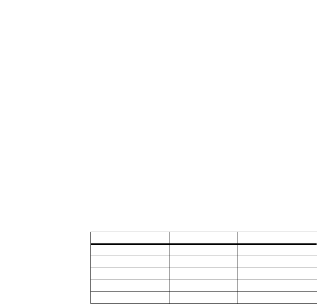
Table 1-1 Applicable Documents
document part number function
GL-T8500/8600 system man-
ual
9110.00163 describes fully racked-up Gold
Line transmitter
VDT manual 9110.00164 describes PA control software
installed in exciter
exciter manual 9110.00172 describes exciter/PA control
equipment in transmitter
250-watt PA 9110.00160 this manual
power supply manual 9110.00159 describes 50A/90A power supply
equipment in transmitter

250-Watt Gold Line Power Amplifier Glenayre Document Number: 9110.00160
GENERAL Issue 1, Rev. C: 10/21/96
Page: 1-2 Copyright © 1996 Glenayre Print Date: 12/17/96
Table 1-2 Manual Sections
section contents
1. General introduction and purpose of manual
2. Specifications significant measurements of power amplifier
3. Description introduction and principal characteristics of power
amplifier
4. Installation and Setup initial installation and activation of power amplifier
5. Operation operation of power amplifier
6. Theory of Operation detailed functional description of circuitry within
power amplifier
7. Maintenance procedures to be performed on specific intervals to
maintain optimum performance of power amplifier
8. Checkout and Troubleshooting verification of proper operation, correction to proper
operation of power amplifier
9. Removal and Reinstallation replacement procedures for power amplifier and
selected subassemblies

Glenayre Document Number: 9110.00160 250-Watt Gold Line Power Amplifier
Issue 1, Rev. C: 10/21/96 SPECIFICATIONS
Print Date: 12/17/96 Copyright © 1996 Glenayre Page: 2-1
2 SPECIFICATIONS
Table 2-1 lists the significant equipment-level specifications for the Gold Line power
amplifier.
Table 2-1 Power Amplifier Specifications
measurement specification
height 8.75 in (22.23 cm)
width 19 in (48.3 cm)
depth 8 in (20.3 cm)
weight 26 lb (12 kg)
RF output power 100 - 250 watts
RF bandwidth 900 - 960 MHz
RF input power 200 - 400 mW
RF impedance 50 ohms
operating voltages 25 vdc, 25 Vdc, 13.5 Vdc
PA 25 Vdc current 72 mA - 33 A
fan 25 Vdc current 750 mA
13.5 Vdc current 3.3 A
ambient temperature -30° - +70° C
humidity 0 - 95% noncondensing
altitude to 10,000 ft (3050 m)
250-Watt Gold Line Power Amplifier Glenayre Document Number: 9110.00160
SPECIFICATIONS Issue 1, Rev. C: 10/21/96
Page: 2-2 Copyright © 1996 Glenayre Print Date: 12/17/96
Glenayre Document Number: 9110.00160 250-Watt Gold Line Power Amplifier
Issue 1, Rev. C: 10/21/96 DESCRIPTION
Print Date: 12/17/96 Copyright © 1996 Glenayre Page: 3-1
3 DESCRIPTION
3.1 Introduction
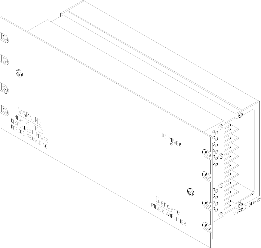
Figure 3-1, 250-Watt, 900-MHz Power Amplifier Front View, and Figure 3-2, 250-Watt,
900-MHz Power Amplifier Rear View,show the Gold Line power amplifier (PA). This is a
250-watt PA intended for use in a GL-T8500 paging transmitter with an RF of 900 MHz
nominal. This PA is characterized by integrated monitoring devices that supply critical
status information to a Gold Line exciter/PA control (exciter). This exciter contains diag-
nostic software that can detect and report a faulty PA circuit board.
3.2 Physical Description
3.2.1 Mounting Provisions
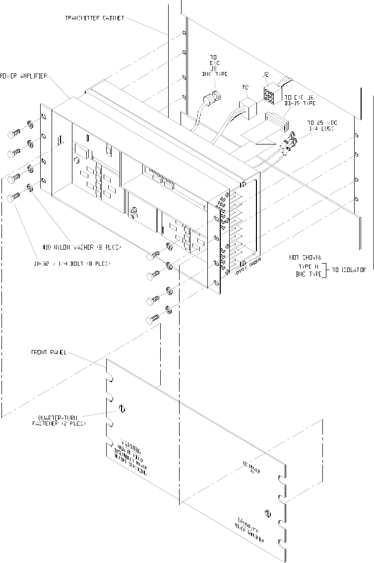
The PA is mounted to the front of most standard 19-inch equipment racks by means of eight
screws. The front panel of the PA may by removed while the PA is mounted in the rack.
Two quarter-turn fasteners secure the front panel to the PA. Most PA circuit boards may be
replaced while the PA is mounted in the rack.
3.2.2 PA Front
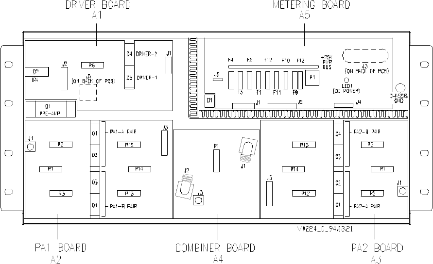
Figure 5-1 shows the front view of the PA with the front panel removed. This exposes the
RF and shielded compartments, which contain the PA circuit boards. Table 3-1 lists the PA
circuit boards.
3.2.2.1 Driver Board
The driver board (A1) contains the preamp module, the intermediate PA (IPA), and the PA
drivers (driver-1 and driver-2). These devices, in addition to one resistor, are mounted
directly on the PA heat sink. The driver board contains three connectors: two on the front
(J1 and J2) and one on the back (J3). Two RG316-type cables (not shown) are attached to
the front of the board.
Table 3-1 PA Circuit Boards
nomenclature part number location
driver board A1 263-0082-022 RF compartment
PA1 board A2 263-0082-007 RF compartment
PA2 board A3 263-0082-007 RF compartment
combiner board A4 263-0082-021 RF compartment
metering board A5 263-0082-018 shielded compartment
250-Watt Gold Line Power Amplifier Glenayre Document Number: 9110.00160
DESCRIPTION Issue 1, Rev. C: 10/21/96
Page: 3-2 Copyright © 1996 Glenayre Print Date: 12/17/96
v0222.hgl
Figure 3-1 250-Watt, 900-MHz Power Amplifier
Front View
Glenayre Document Number: 9110.00160 250-Watt Gold Line Power Amplifier
Issue 1, Rev. C: 10/21/96 DESCRIPTION
Print Date: 12/17/96 Copyright © 1996 Glenayre Page: 3-3
v0221.hgl
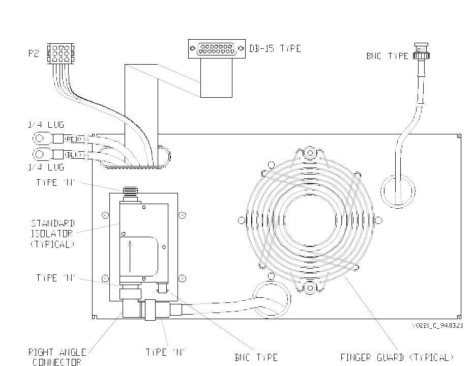
Figure 3-2 250-Watt, 900-MHz Power Amplifier
Rear View
250-Watt Gold Line Power Amplifier Glenayre Document Number: 9110.00160
DESCRIPTION Issue 1, Rev. C: 10/21/96
Page: 3-4 Copyright © 1996 Glenayre Print Date: 12/17/96
3.2.2.2 PA Boards
Two PA boards, PA1 (A2) and PA2 (A3), contain the power amplifiers. The PA boards are
identical but are mounted with different orientations. Each PA board contains an A and a B
pair of power amplifiers. These amplifiers and six resistors are mounted directly on the PA
heat sink. Connectors J1 and J3 and an RG142-type cable (not shown) are attached to the
front of each board.
3.2.2.3 Combiner Board
The combiner board combines the outputs of the PA boards. The combiner board contains
a resistor, mounted directly on the PA heat sink. Connectors J1, J2, and J3 are on the front
of the board. An RG393-type cable is attached to the back of the board. This cable termi-
nates with a type-N connector and extends through the rear of the PA.
3.2.2.4 Metering Board
The metering board contains the monitoring circuits for the PA. A bank of nine automotive
spade-type fuses protect the PA. A transistor is mounted directly on the PA heat sink. The
metering board contains connectors J1, J2, J4, J5, and P1 on the front and J3 on the back.
The board contains one LED (DC POWER).
3.2.3 PA Rear
Figure 3-2 shows the back view of the PA. The PA back panel conceals the fan compart-
ment. The isolator and fan are mounted on the back panel. The PA equipment connectors
terminate on cables that are routed through grommeted holes in the back panel.
3.2.3.1 Isolator
The standard isolator (shown) improves the intermodulation performance of the PA by 25
dB. This isolator is mounted on its own heat sink, which extends into the fan compartment.
The optional triple isolator (not shown) improves the intermodulation performance of the
PA by 75 dB, and is mounted on the PA. Both isolators contains three connectors: two type-
N and one BNC.
3.2.3.2 Fan
A single fan provides cooling for the PA and standard isolator. The fan is located within the
fan compartment and is covered by a finger guard. The fan runs continuously whenever
power is applied by the power supply equipment.
3.2.3.3 Equipment Connectors
There are five equipment connectors in addition to those on the isolator. Two 1/4-inch ring
lugs are designated as plus (red) and minus (black). A 9-pin plug-and-socket connector is
designated as P2. A DB15-type connector is designated as PA CONTROL. A BNC
connector is designated as P3.
Glenayre Document Number: 9110.00160 250-Watt Gold Line Power Amplifier
Issue 1, Rev. C: 10/21/96 DESCRIPTION
Print Date: 12/17/96 Copyright © 1996 Glenayre Page: 3-5
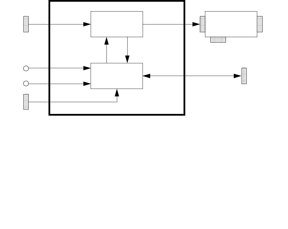
3.3 Functional Description
Figure 3-3 shows a simplified, functional diagram of the PA. The driver, combiner, and PA
boards constitute the RF amplifier circuitry of the PA. Monitoring and controlling this RF
amplifier is the metering board. Figure 3-1 shows the RF amplifier, isolator, and metering
circuitry within the PA.
Figure 3-3 PA Simplified-Block Diagram
3.3.1 RF Amplifier
The RF amplifier receives its RF input through the BNC connector P3. A detector circuit
in the RF amplifier monitors this RF input. The RF input is amplified by means of four
amplifier stages. Each amplifier stage receives its dc input power through the metering
circuit. Power detectors at critical locations throughout the RF amplifier provide sample
voltages to the metering circuit. The amplified output of the RF amplifier is applied to the
input type-N connector on the isolator.
3.3.2 Isolator
The isolator prevents intermodulation of the RF signal that may occur from nearby trans-
missions. The RF signal is routed through input and output type N connectors. A detector
circuit in the isolator monitors the reflected power (VSWR) present at the output type-N
connector. A sample voltage representing the VSWR level is output through the BNC
connector. The optional triple isolator functions identically to the standard isolator except
with a higher level of intermodulation prevention.
BNC
STATUS/
CONTROL
RF
AMPLIFIER
RF
IN ISOLATOR RF
OUT
METERING
METERED
POWER
STATUS
VOLTAGES
DC
IN
25V
13.5V
TYPE N TYPE N
DB-15
VSWR
SAMPLE
BNC
1/4 LUGS
P2
POWER
AMPLIFIER
250-Watt Gold Line Power Amplifier Glenayre Document Number: 9110.00160
DESCRIPTION Issue 1, Rev. C: 10/21/96
Page: 3-6 Copyright © 1996 Glenayre Print Date: 12/17/96
3.3.3 Metering
The metering board performs control and status reporting for the PA. The metering board
accepts a 25-Vdc power input through the 1/4-inch lugs and a 13.5-Vdc power input
through connector P2. These voltages are regulated and distributed.

Glenayre Document Number: 9110.00160 250-Watt Gold Line Power Amplifier
Issue 1, Rev. C: 10/21/96 INSTALLATION AND SETUP
Print Date: 12/17/96 Copyright © 1996 Glenayre Page: 4-1
4 INSTALLATION AND SETUP
4.1 Installation
The PA is shipped already installed in a cabinet. To remove or reinstall the PA, refer to
Section 9.
4.2 Setup
Setup of the PA is performed at the system level using an exciter/PA control unit. Refer to
the GL-T8500 system manual. The system manual includes instructions for these
applicable setup procedures:
•adjust forward power
•set low power alarm
•calibrate reflected power
4.3 Ultimate Disposition
Caution
This equipment may contain hazardous materials.
Check with the local EPA or other environmental
authority before disposing of this equipment.
250-Watt Gold Line Power Amplifier Glenayre Document Number: 9110.00160
INSTALLATION AND SETUP Issue 1, Rev. C: 10/21/96
Page: 4-2 Copyright © 1996 Glenayre Print Date: 12/17/96

Glenayre Document Number: 9110.00160 250-Watt Gold Line Power Amplifier
Issue 1, Rev. C: 10/21/96 OPERATION
Print Date: 12/17/96 Copyright © 1996 Glenayre Page: 5-1
5 OPERATION
5.1 Controls and Indicators
The PA has one indicator and no controls. Figure 5-1, Front-Panel View with Cover
Removed shows the location of the PA indicator LED1.
5.2 Operation
5.2.1 Turn PA On and Off
The PA does not contain an on/off switch, but turns on and off whenever the power supply
equipment is turned on and off. When the PA is on, it remains in a standby condition until
keyed. Refer to the power supply manual for turn-on and turn-off procedures.
5.2.2 Turn Fan On and Off
The fan does not contain an on/off switch, but turns on and off whenever the power supply
equipment is turned on and off. The fan runs continuously whenever the power supply
equipment is on. Refer to the power supply manual for turn-on and turn-off procedures.
5.2.3 Key and Unkey PA
The PA does not contain a key switch, but is keyed and unkeyed by the exciter/PA control
equipment. This exciter must be keyed and unkeyed remotely through transmitter
controller, or locally through a video display terminal (VDT). Refer to the controller
manual for remote key and unkey instructions, or to the VDT manual for local key and
unkey instructions.
250-Watt Gold Line Power Amplifier Glenayre Document Number: 9110.00160
OPERATION Issue 1, Rev. C: 10/21/96
Page: 5-2 Copyright © 1996 Glenayre Print Date: 12/17/96
v0224.hgl
Figure 5-1 Front-Panel View with Cover Removed

Glenayre Document Number: 9110.00160 250-Watt Gold Line Power Amplifier
Issue 1, Rev. C: 10/21/96 THEORY OF OPERATION
Print Date: 12/17/96 Copyright © 1996 Glenayre Page: 6-1
6 THEORY OF OPERATION
6.1 Power Distribution
The PA requires three separate power inputs: primary 25-volt dc power, secondary 13.5-
volt dc power, and fan 25-volt dc power. All power inputs are normally provided by the
Gold Line power supply.
6.1.1 Primary Power
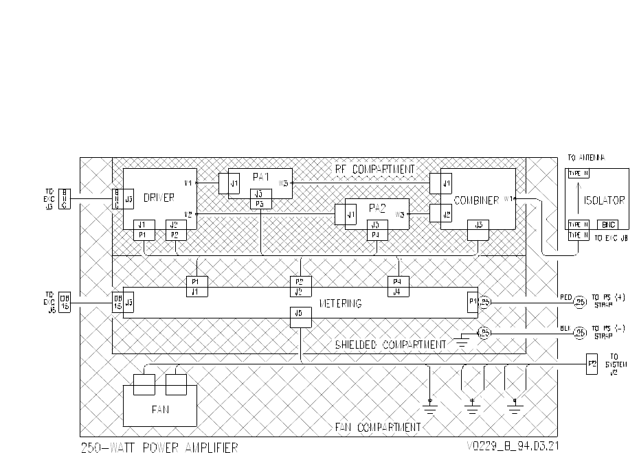
Refer to Figure 6-2. Primary 25-volt dc operating power is received through the power
cables terminating with 1/4-inch ring lugs. The (-) input (black cable) is bolted directly to
PA chassis ground. The (+) input (red cable) is bolted to P1 on the metering board. P1
powers the +25V power bus on the metering board. This bus distributes primary power to
the metering board and to each common-base collector (CBC) power amplifier in the PA.
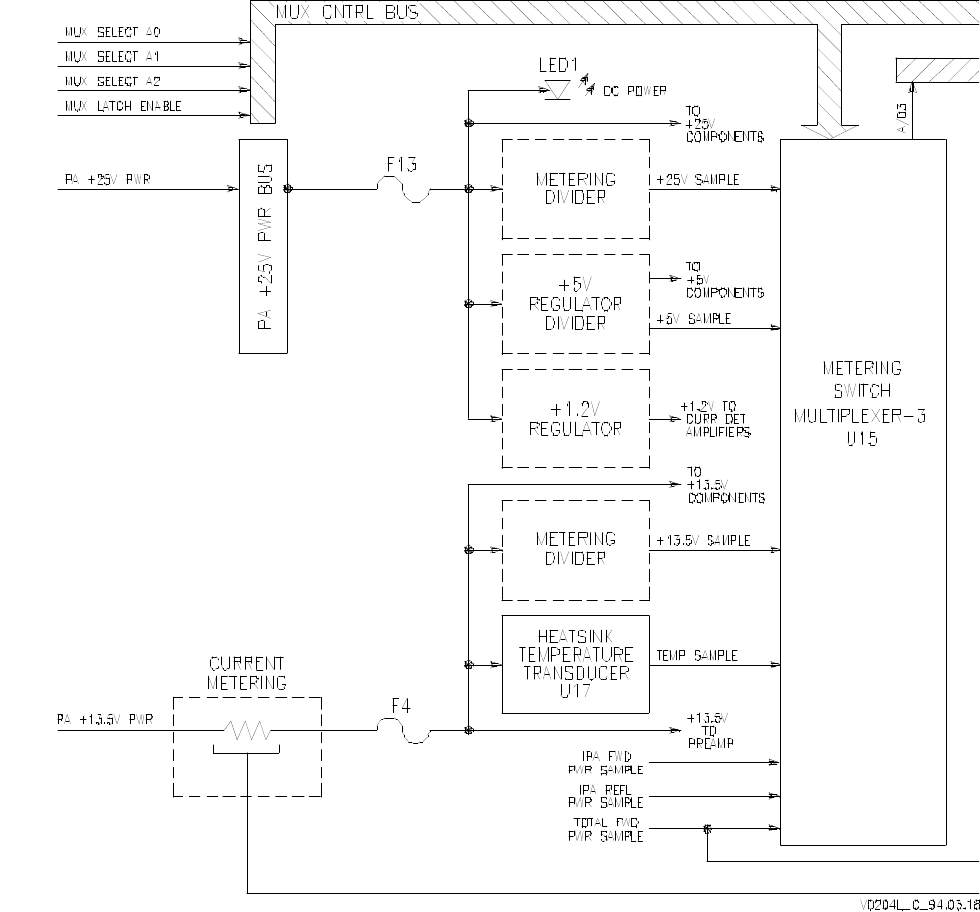
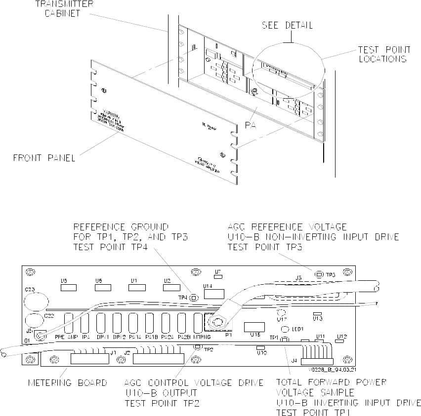
6.1.1.1 Metering Board +25V Signal Flow
Refer to Figure 6-4. +25 volts from the power bus is supplied through fuse F13 to these
places on the metering board: LED1, +25V components, divider circuitry, +5V regulator
and divider circuitry, and +1.2V regulator circuitry.
•LED1 activates to illuminate the DC POWER indicator on the front of the PA.
•+25V components receive operating power. These components include the current
detector amplifiers.
•Divider circuit reduces the input to a sample voltage, which determines the PA 25V
metering.
•+5V regulator/divider circuitry generates +5V operating power for the metering board
+5V components. A portion of this +5V is reduced to a sample voltage, which deter-
mines the PA 5V metering.
•+1.2V regulator circuitry generates the compensation voltage for the current detector
amplifiers.
6.1.1.2 Power Amplifiers +25V Signal Flow
Refer to Figure 6-1. +25 volts operating power from the power bus is paralleled through
seven resistors. These resistors are a component of a current detection circuit.
Current-Detection Theory
Current-detection monitoring occurs on the metering board. The monitored current is
routed through a small resistor, resulting in a slight voltage drop across the resistor.
This voltage drop is amplified by a current detector amplifier, which generates an out-
put voltage proportional to the current flowing through the resistor. This output voltage
is the current sample for the monitored current.

250-Watt Gold Line Power Amplifier Glenayre Document Number: 9110.00160
THEORY OF OPERATION Issue 1, Rev. C: 10/21/96
Page: 6-2 Copyright © 1996 Glenayre Print Date: 12/17/96
The seven monitored +25-volt signals are individually fused before leaving the metering
board. The signals provide operating power for power amplifiers located on the driver and
PA boards. Each signal is routed through a dc bias network.
6.1.2 Secondary Power
Secondary 13.5-volt dc power for the PA is externally fused, at the power supply equip-
ment. Refer to Figure 6-1. Secondary power is received through connector P2, which
mates with J2 on the system interconnect harness. Secondary power is connected to J5 on
the metering board. The +13.5 input from J5 is distributed to the metering board and the
preamp module.
6.1.2.1 Metering Board +13.5V Signal Flow
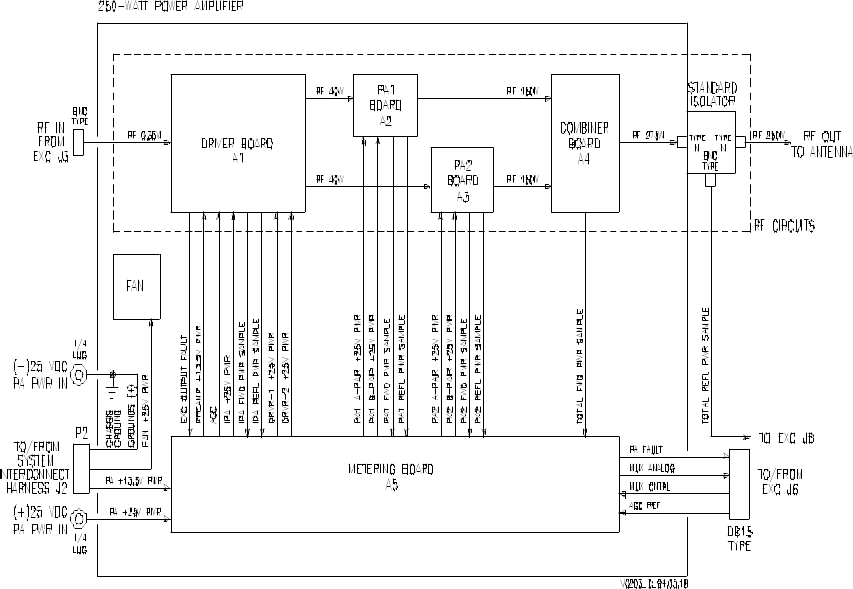
Refer to Figure 6-2. +13.5-volt power from J5 is paralleled to these places on the metering
board: +13.5V components, divider circuitry, and heat sink temperature transducer U17.
•+13.5V components receive operating power. These components include those within
the AGC integrator circuit.
•Divider circuit reduces the input to a sample voltage, which determines the system PA
13.5V metering.
•Heat-sink-temperature transducer U17 generates a voltage proportional to the tempera-
ture of the PA heat sink, which determines the temperature metering.
6.1.2.2 Preamplifier Module +13.5V Signal Flow
Refer to Figure 6-2. +13.5-volt power from J5 is routed through a resistor, a component of
a current-detection circuit. The sample provided by this circuit determines the preamplifier
current metering. The +13.5-volt power through the resistor is fused by F4 before distribu-
tion to the metering board and preamplifier module, on the driver board.
6.1.3 Fan Power
25-volt dc fan power is fused externally at the power supply equipment. Refer to Figure 6-
1. Fan power is received through connector P2, which mates with J2 on the system inter-
connect harness. Fan power is applied directly to the fan via a quick-release jack (not
shown).
Dc-Bias Network Theory
Dc bias networks are located on the driver board and PA boards. +25-volt operating
power from the metering board is applied to the power amplifiers through a dc bias net-
work. The network is tuned and filtered to cause a high impedance to signals from dc to
above operating frequency. This prevents RF from transmitting backwards into the me-
tering board.

Glenayre Document Number: 9110.00160 250-Watt Gold Line Power Amplifier
Issue 1, Rev. C: 10/21/96 THEORY OF OPERATION
Print Date: 12/17/96 Copyright © 1996 Glenayre Page: 6-3
6.2 RF Distribution
Refer to Figure 6-1. The PA RF input is received through a BNC connector, which mates
with J3 on the exciter/PA control. This RF input signal (at a nominal 350 mW) is split and
amplified into two RF signals (at a nominal 40 watts) by the driver board. Each RF signal
is amplified (to a nominal 150 watts) by a PA board. These RF signals are combined into
one RF signal (at a nominal 275 watts) by the combiner board. This is the PA RF output,
and is applied to an isolator. The isolator RF output (at a nominal 250 watts for standard)
is supplied to an antenna for transmission. All power levels given here and in the following
paragraphs are typical; actual power levels will vary from those given.
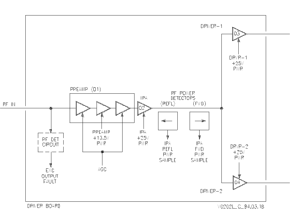
6.2.1 Driver Board RF Flow
The driver board splits and amplifies a 350-mW RF input into two 40-watt RF outputs.
Refer to Figure 6-3. The RF input to the driver board is applied to the preamplifier module
(Q1). A portion of the RF input is applied to an RF-detection circuit on the board. This
circuit rectifies and filters the RF input into an OK signal. Loss of the RF input and the OK
signal results in an exciter output fault.
The preamplifier module is a three-stage RF power amplifier on a single IC. The first and
third stages are powered by an AGC signal. These are the variable gain stages, and control
the forward power output of the PA. The first and third stages of the preamp module are
powered by an AGC signal, generated on the metering board. AGC signal voltage is
monitored for status only. The second stage of the preamplifier module is a nonvariable-
gain stage, powered by +13.5-volt power. The current drawn by the AGC and +13.5-volt
power signals contributes to the preamplifier current metering.
The amplified RF output from the preamp module is applied to the IPA (Q2). The current
drawn from the IPA’s +25-volt power source is monitored to determine the IPA current
metering. The amplified RF output from the IPA is monitored for forward and reflected
power levels. The power samples detected at this location determine the IPA forward - and
reflected-power metering.
Power-Monitoring Theory
Power-monitor circuits are located on the driver board, PA boards, and combiner
board. A microstrip line parallel to the RF signal path couples a small portion of the ac
signal across a rectifier and filtering circuit. The ac signal may be rectified to detect ei-
ther the forward or reflected power. After filtering, a dc sample voltage is available that
is proportional to the power detected at the monitored location.

250-Watt Gold Line Power Amplifier Glenayre Document Number: 9110.00160
THEORY OF OPERATION Issue 1, Rev. C: 10/21/96
Page: 6-4 Copyright © 1996 Glenayre Print Date: 12/17/96
After monitoring, the amplified RF output from the IPA is split in two by means of an RF
splitter, commonly known as a Wilkinson splitter. The two split RF signals are applied to
driver-1 (Q3) and driver-2 (Q4). The current drawn from each driver’s +25-volt power
source is monitored to determine the driver-1 and driver-2 current metering. The amplified
RF outputs from the two drivers are the driver board’s 40-watt RF outputs.
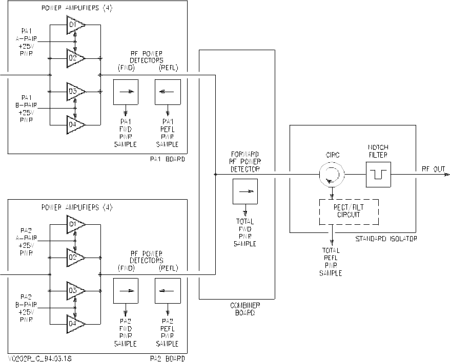
6.2.2 PA Board RF Flow
Each PA board amplifies a 40-watt RF input into a 150-watt RF output. Refer to Figure 6-
3. The RF input to the PA board is split into four signals by means of three Wilkinson split-
ters. Each RF signal drives a power amplifier, for a total of four amplifiers (Q1, Q2, Q3,
and Q4). Q1 and Q2 receive operating power from a common +25-volt power source. The
current drawn by this source is monitored to determine the PA board’s A-pair current.
Likewise, the current drawn by Q3 and Q4 common +25-volt power source is monitored to
determine the PA board’s B-pair current.
The amplified RF outputs from the four power amplifiers are combined into one by means
of three Wilkinson combiners. The RF signal from the last Wilkinson combiner is
monitored for forward and reflected power levels. The power samples detected at this
location determine the PA board’s forward and reflected power metering. The combined
and monitored RF signal is the PA board’s 150-watt RF output.
6.2.3 Combiner Board RF Flow
The combiner board combines two 150-watt RF inputs into a single 275-watt RF output.
Refer to Figure 6-3. The two RF inputs are combined by a Wilkinson combiner. The
combined RF is monitored for forward power level. The power sample detected at this
location determines the total forward power metering. The combined and monitored signal
is the combiner board’s 275-watt RF output.
6.2.4 Isolator RF Flow
The isolator conducts its 275-watt RF input only in the forward direction, suppressing any
intermodulation or VSWR present at its RF output. Refer to Figure 6-3. The RF input is
applied through a circulator. The optional triple isolator RF input is applied through three
circulators.
Wilkinson Splitter/Combiner Theory
Wilkinson splitter and combiner networks are located in the RF signal path on the driv-
er board, PA boards, and combiner board. A waster resistor is located a precise dis-
tance from the signal junction. This resistor dissipates any out-of-phase imbalance or
amplifier imbalance that may exist between the RF signals being split or combined, re-
sulting in a more stable amplifier.
Circulator Theory
A circulator consists of several circular layers of copper, ferrite, and a magnetic materi-
al that biases the ferrite. The circulator has three inputs/outputs. The biased ferrite con-
ducts electricity only in one direction, outputting the signal applied at its previous
input. Each circulator provides 25 dB of isolation.

Glenayre Document Number: 9110.00160 250-Watt Gold Line Power Amplifier
Issue 1, Rev. C: 10/21/96 THEORY OF OPERATION
Print Date: 12/17/96 Copyright © 1996 Glenayre Page: 6-5
The circulator RF output is applied through a notch filter to remove the second harmonics
generated by the circulator. This filtered RF is the isolator’s RF output. This RF output is
typically 250 watts for a standard isolator or 225 watts for a triple isolator. Any reflected
power present at the isolator RF output is conducted back through the circulator to a
rectifier and filtering circuit. This circuit generates a dc sample voltage proportional to the
VSWR present at the isolator RF output. The sample voltage determines the total reflected-
power metering.
6.3 Control Distribution
Refer to Figure 6-1. The PA control inputs are received through a DB15 connector, which
mates with J6 on the exciter/PA control. Two types of control inputs are received: AGC
reference and multiplexer.
6.3.1 AGC Signal Flow
The metering board compares the AGC reference signal (from the exciter) with the total
forward power sample (from the combiner board) to create an AGC signal (to the driver
board). Refer to Figure 6-2. The AGC reference signal and the total forward power sample
are applied to an integrator circuit, which generates the AGC signal. An increase in the
AGC reference signal or a decrease in the total forward power sample causes an increase
in the AGC signal. This AGC signal provides operating power for the first and third
amplifier stages of the preamplifier. Divider circuitry reduces a portion of the AGC signal
to a sample voltage, which determines the AGC metering.
6.3.2 Multiplexer Control Signal Flow
Refer to Figure 6-2. The exciter controls each multiplexer by four control lines: three
address lines and a latch. The address lines (0, 1, and 2) are binary signals with a total of
eight possible states. The address lines sequence through the eight states in about 360
microseconds. As each state occurs, the latch line is toggled, selecting the analog input
corresponding to that address state. The voltage present at the multiplexer common output
is the most recently latched analog input.
6.4 Status Distribution
Refer to Figure 6-1. The PA status outputs are supplied through the same DB15-type
connector as the PA control inputs, which mates with J6 on the exciter/PA control. Two
types of status outputs are supplied: multiplexed (mux) analog and PA fault.
Analog Multiplexer Theory
Three analog multiplexers are located on the metering board. Each multiplexer re-
ceives as many as eight analog inputs, at a sample voltage which represents a PA pa-
rameter or status. Control lines from the exciter command the multiplexer to connect
one of the inputs to a common output, which is measured by the exciter. The multi-
plexer is switched quickly between the analog inputs, resulting in a multiplexed analog
output.

250-Watt Gold Line Power Amplifier Glenayre Document Number: 9110.00160
THEORY OF OPERATION Issue 1, Rev. C: 10/21/96
Page: 6-6 Copyright © 1996 Glenayre Print Date: 12/17/96
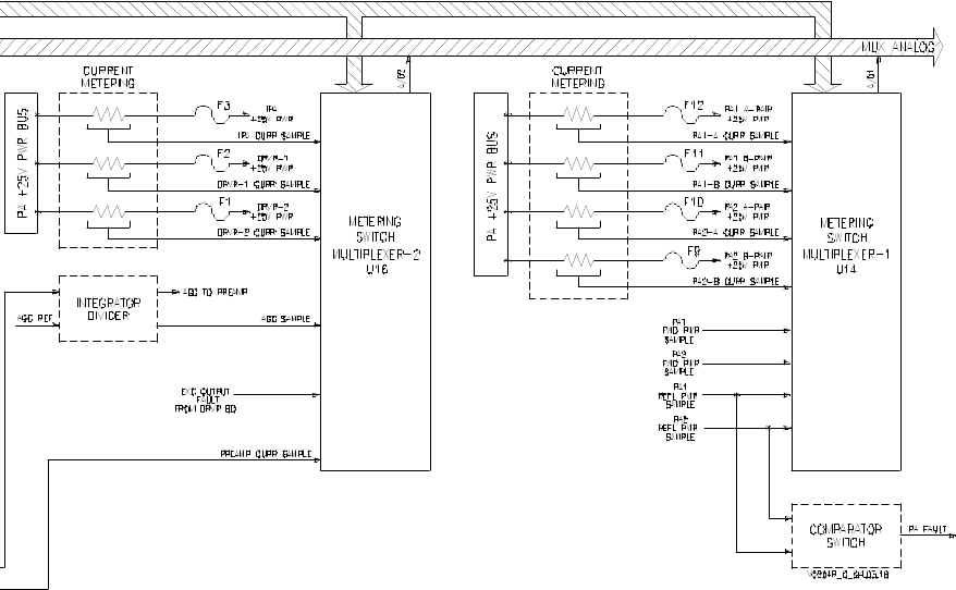
6.4.1 Mux Analog Status Signal Flow
Mux analog status signals consist of dc voltages that represent a parameter or fault within
the PA. These signals are generated by current detectors, power monitors, and metering
dividers, which supply a status voltage proportional to the level of parameter it is repre-
senting, or the existence of the fault it is representing. Refer to Figure 6-2. These status
voltages are applied to one of the three multiplexers located on the metering board. The
multiplexers route the appropriate status voltage to the exciter in the form of mux analog.
Table 6-1 lists all status voltage nomenclature, the multiplexer that routes that voltage, and
the control address that directs the multiplexer to route that voltage.
6.4.2 PA Fault Signal Flow
A PA fault signal is activated when a reflected power threshold is exceeded by the PA1 or
PA2 board. Refer to Figure 6-2. A portion of the PA1 board and PA2 board reflected power
status voltages are applied to a comparator and switching circuit. When either status
exceeds a voltage representing about 20 watts, the switch is activated. The switch applies
a PA fault to the exciter, which shuts down the transmitter.
Table 6-1 Multiplexer Analog Status Inputs
addr multiplexer 1 multiplexer 2 multiplexer 3
000 PA1-A current preamp current total forward power
001 PA1-B current IPA current (no input)
010 PA2-A current driver-1 current IPA forward power
011 PA2-B current driver-2 current IPA reflected power
100 PA1 forward power (no input) +25V voltage level
101 reflected power (no input) +13.5V voltage level
110 PA2 forward power exciter output fault +5V voltage level
111 PA2 reflected power AGC voltage level PA heat sink temp
Glenayre Document Number: 9110.00160 250-Watt Gold Line Power Amplifier
Issue 1, Rev. C: 10/21/96 THEORY OF OPERATION
Print Date: 12/17/96 Copyright © 1996 Glenayre Page: 6-7
v0229.hgl
Figure 6-1 250-Watt PA Interconnection Diagram
250-Watt Gold Line Power Amplifier Glenayre Document Number: 9110.00160
THEORY OF OPERATION Issue 1, Rev. C: 10/21/96
Page: 6-8 Copyright © 1996 Glenayre Print Date: 12/17/96
v0203.hgl
Figure 6-2 250-Watt PA Functional Diagram
Glenayre Document Number: 9110.00160 250-Watt Gold Line Power Amplifier
Issue 1, Rev. C: 10/21/96 THEORY OF OPERATION
Print Date: 12/17/96 Copyright © 1996 Glenayre Page: 6-9
v0202l.hgl
Figure 6-3 250-Watt PA Detailed Functional Diagram
250-Watt Gold Line Power Amplifier Glenayre Document Number: 9110.00160
THEORY OF OPERATION Issue 1, Rev. C: 10/21/96
Page: 6-10 Copyright © 1996 Glenayre Print Date: 12/17/96
v0202r.hgl
250-Watt PA Detailed Functional Diagram
Glenayre Document Number: 9110.00160 250-Watt Gold Line Power Amplifier
Issue 1, Rev. C: 10/21/96 THEORY OF OPERATION
Print Date: 12/17/96 Copyright © 1996 Glenayre Page: 6-11
v0204l.hgl
Figure 6-4 Metering Board Functional Diagram
250-Watt Gold Line Power Amplifier Glenayre Document Number: 9110.00160
THEORY OF OPERATION Issue 1, Rev. C: 10/21/96
Page: 6-12 Copyright © 1996 Glenayre Print Date: 12/17/96
0204r.hgl
Metering Board Functional Diagram

Glenayre Document Number: 9110.00160 250-Watt Gold Line Power Amplifier
Issue 1, Rev. C: 10/21/96 MAINTENANCE
Print Date: 12/17/96 Copyright © 1996 Glenayre Page: 7-1
7 MAINTENANCE
Refer to the system and VDT manuals.
250-Watt Gold Line Power Amplifier Glenayre Document Number: 9110.00160
MAINTENANCE Issue 1, Rev. C: 10/21/96
Page: 7-2 Copyright © 1996 Glenayre Print Date: 12/17/96

Glenayre Document Number: 9110.00160 250-Watt Gold Line Power Amplifier
Issue 1, Rev. C: 10/21/96 CHECKOUT AND TROUBLESHOOTING
Print Date: 12/17/96 Copyright © 1996 Glenayre Page: 8-1
8 CHECKOUT AND TROUBLESHOOTING
Refer to the system and VDT manuals.
250-Watt Gold Line Power Amplifier Glenayre Document Number: 9110.00160
CHECKOUT AND TROUBLESHOOTING Issue 1, Rev. C: 10/21/96
Page: 8-2 Copyright © 1996 Glenayre Print Date: 12/17/96

Glenayre Document Number: 9110.00160 250-Watt Gold Line Power Amplifier
Issue 1, Rev. C: 10/21/96 REMOVAL AND REINSTALLATION
Print Date: 12/17/96 Copyright © 1996 Glenayre Page: 9-1
9 REMOVAL AND REINSTALLATION
9.1 PA Chassis Removal and Reinstallation
Figure 9-1 shows details of removing and reinstalling the chassis. Calibration of forward
and reflected power is required after reinstallation.
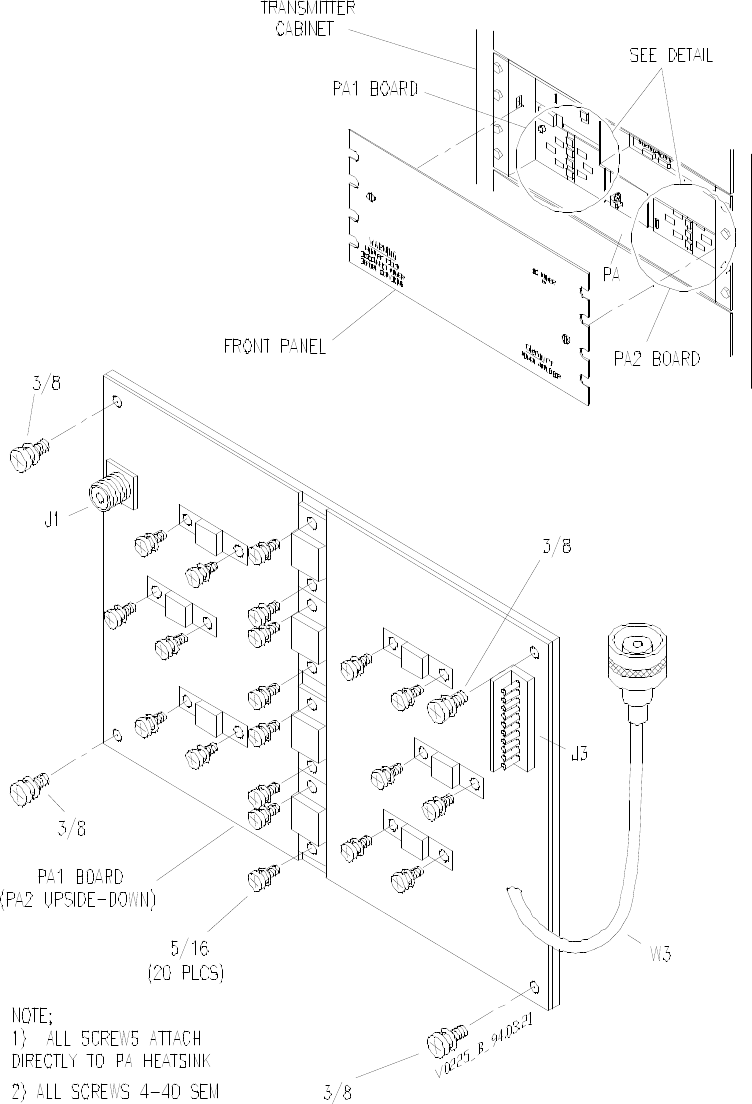
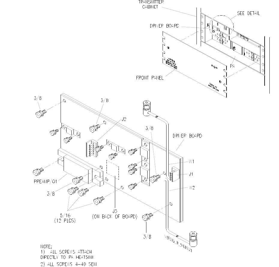
9.2 PA RF Module Removal and Reinstallation
Figure 9-2 shows details of removing and reinstalling PA RF modules.
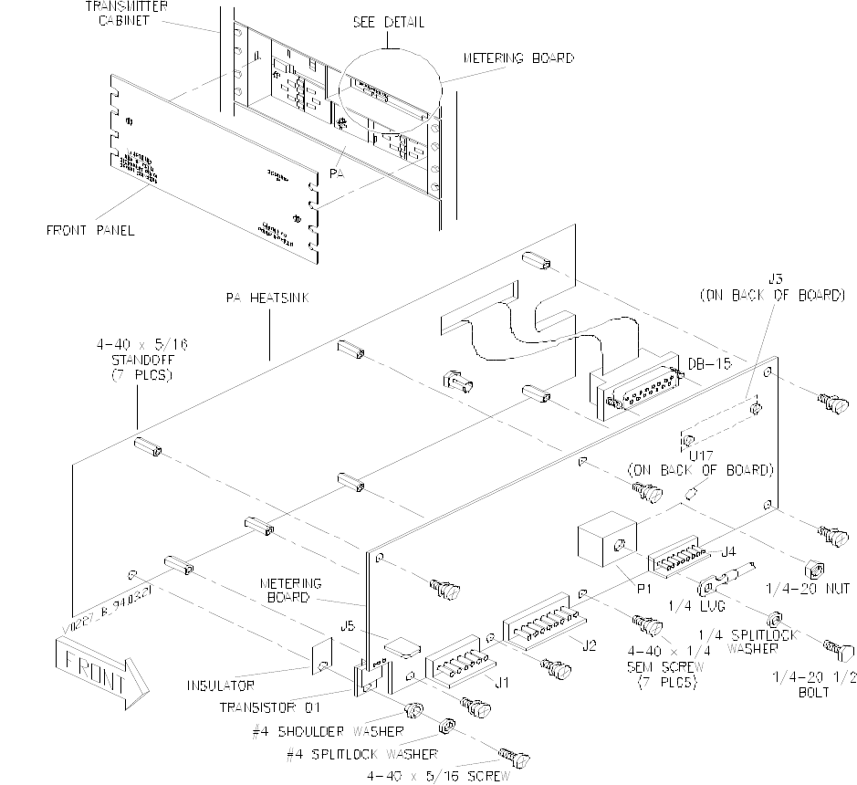
9.3 Metering Board Removal and Reinstallation
Figure 9-3 shows details of removing and reinstalling the metering board.
250-Watt Gold Line Power Amplifier Glenayre Document Number: 9110.00160
REMOVAL AND REINSTALLATION Issue 1, Rev. C: 10/21/96
Page: 9-2 Copyright © 1996 Glenayre Print Date: 12/17/96
v0223.hgl
Figure 9-1 PA Removal and Reinstalllation

Glenayre Document Number: 9110.00160 250-Watt Gold Line Power Amplifier
Issue 1, Rev. C: 10/21/96 REMOVAL AND REINSTALLATION
Print Date: 12/17/96 Copyright © 1996 Glenayre Page: 9-3
250-Watt Gold Line Power Amplifier Glenayre Document Number: 9110.00160
REMOVAL AND REINSTALLATION Issue 1, Rev. C: 10/21/96
Page: 9-4 Copyright © 1996 Glenayre Print Date: 12/17/96
v0225.hgl
Figure 9-2 PA RF Module Removal and Reinstallation
250-Watt Gold Line Power Amplifier Glenayre Document Number: 9110.00160
REMOVAL AND REINSTALLATION Issue 1, Rev. C: 10/21/96
Page: 9-6 Copyright © 1996 Glenayre Print Date: 12/17/96
v0228.hgl
Figure 9-3 Metering Board Removal and Reinstallation
Glenayre Document Number: 9110.00160 250-Watt Gold Line Power Amplifier
Issue 1, Rev. C: 10/21/96 REMOVAL AND REINSTALLATION
Print Date: 12/17/96 Copyright © 1996 Glenayre Page: 9-7
v0227.hgl
Figure 9-3 Metering Board Removal and Reinstallation (continued)
250-Watt Gold Line Power Amplifier Glenayre Document Number: 9110.00160
REMOVAL AND REINSTALLATION Issue 1, Rev. C: 10/21/96
Page: 9-8 Copyright © 1996 Glenayre Print Date: 12/17/96