Global Microwave Systems VMT-F2 Digital 100mW Transmitter User Manual 100 M0169Xmods
Global Microwave Systems, Inc. Digital 100mW Transmitter 100 M0169Xmods
User Manual
Cobham Surveillance
GMS Products
1916 Palomar Oaks Way Ste 100
Carlsbad, CA 92008
100-M0169X1 11-15-11 T: 760-496-0055
F: 760-496-0057
www.cobham.com/gms
Technical Operations Manual
The most important thing we build is trust.
VETA Miniature Transmitter
(VMT)

REVISION HISTORY
Version
Date
Author
Comments
X1
11/15/11
Thad Giotta
Initial release
FCC version VMT ISM band

100-M0169X1 11-15-11
3 of 24
www.cobham.com/gms
Table of Contents
1.0
Information to User ................................................................................................................................................................ 5
2.0
Important Warning and General Safety Information .......................................................................................................... 6
3.0
Acronyms ................................................................................................................................................................................ 8
4.0
Introduction ............................................................................................................................................................................ 9
4.1
Key System Features ....................................................................................................................................................... 10
4.2
Warranty ........................................................................................................................................................................... 10
4.3
Safe Operating Procedures .............................................................................................................................................. 10
5.0
General System Information ............................................................................................................................................... 11
5.1
Getting Started ................................................................................................................................................................. 11
5.2
Initial Checkout ................................................................................................................................................................. 11
5.2.1
Initial Checkout of VMT ........................................................................................................................................... 12
5.2.2
Setup of Corresponding VETA Receiver ................................................................................................................. 13
6.0
Hardware Overview .............................................................................................................................................................. 15
6.1
VMT Interface Connectors ............................................................................................................................................... 15
6.1.1
RF Out ........................................................................................................................................................................ 15
6.1.2
I/O .............................................................................................................................................................................. 15
6.2
Local Control ..................................................................................................................................................................... 17
6.2.1
Set-Up Group Select Switch .................................................................................................................................... 17
7.0
Remote Control of VMT ....................................................................................................................................................... 18
7.1
VETA Remote Control Unit – VRCU ................................................................................................................................ 18
8.0
Software Overview ............................................................................................................................................................... 19
9.0
VETA Chaining Feature ........................................................................................................................................................ 20
9.1
VETA Digital Repeater (VDR) .......................................................................................................................................... 20
9.2
Compact Surveillance Modem (CSM) ............................................................................................................................. 20
9.3
UDP Transmitter .............................................................................................................................................................. 20
10.0
Specifications ........................................................................................................................................................................ 21
10.1
COFDM RF Output ........................................................................................................................................................ 21
10.2
Modulation .................................................................................................................................................................... 21
10.3
Video Encoding ............................................................................................................................................................. 21
10.4
Audio Encoding ............................................................................................................................................................. 21
10.5
RS232 Data Input .......................................................................................................................................................... 22
10.6
Security Option ............................................................................................................................................................. 22
10.7
Physical ......................................................................................................................................................................... 22
10.8
Environmental .............................................................................................................................................................. 22
10.9
DC Power ....................................................................................................................................................................... 22
10.10
Control ........................................................................................................................................................................... 22

100-M0169X1 11-15-11
4 of 24
www.cobham.com/gms
List of Tables
Table 1 RF Connector ........................................................................................................................................................................ 15
Table 2 JST Connector (21 Pins) ....................................................................................................................................................... 16
Table 3 Rotary Switch Configurations ............................................................................................................................................... 18
List of Figures
Figure 5.1 Basic VDL Setup ............................................................................................................................................................. 11
Figure 5.2 VMT RF Essentials .......................................................................................................................................................... 13
Figure 6.1 VMT Interface Connectors ............................................................................................................................................... 15
Figure 6.2 VMT with Rotary Switch ................................................................................................................................................. 17
Figure 7.1 VETA Remote Control Unit ............................................................................................................................................ 18
List of Appendixes
Appendix A: Standard Breakout Cable .......................................................................................................................................... 23

100-M0169X1 11-15-11
5 of 24
www.cobham.com/gms
1.0 Information to User
This device complies with Part 15 of the FCC Rules. Operation is subject to the following two
conditions:
(1) This device may not cause harmful interference, and
(2) This device must accept any interference received, including interference that may cause undesired
operation.
This equipment has been tested and found to comply with the limits for Class B Digital Device,
pursuant to Part 15 of the FCC Rules. These limits are designed to provide reasonable protection
against harmful interference in a residential installation. This equipment generates and can radiate
radio frequency energy and, if not installed and used in accordance with the instructions, may cause
harmful interference to radio communications. However, there is no guarantee that interference will
not occur in a particular installation. If this equipment does cause harmful interference to radio or
television reception, which can be determined by turning the equipment off and on, the user is
encouraged to try to correct the interference by one or more of the following measures:
• Reorient or relocate the receiving antenna
• Increase the separation between the equipment and receiver
• Connect the equipment into an outlet on a circuit different from that to which the receiver is
connected
• Consult the dealer or an experienced radio/TV technician for help

100-M0169X1 11-15-11
6 of 24
www.cobham.com/gms
2.0 Important Warning and General Safety Information
The following information is presented to the operator to ensure awareness of potential harmful RF
(radio frequency) exposure and general hazards. With regards to potential harmful RF
electromagnetic fields the text below is only a brief summary highlighting the possible risks and how to
minimize exposure. The summary is based on OET Bulletin 65 “Evaluating Compliance with FCC
Guidelines for Human Exposure to Radiofrequency Electromagnetic Fields”
(1)
. The user should
carefully read and comprehend the following before operating the equipment. For additional in depth
information refer to OET Bulletin 65.
1. FCC has set guidelines
(1)
for evaluating exposure to RF emissions that the user must be aware
of when operating the VMT (VETA miniature transmitter) microwave transmitter. The
maximum power density allowed at 2412-2472MHz is 5mW/cm
2
for occupational/controlled
exposure* and 1mW/cm
2
for general population/uncontrolled exposure**. These are the limits
for maximum permissible exposure (MPE) as called out in the FCC guidelines (for the above
mentioned frequencies).
2. Exposure is based upon the average time spent within the RF field with a given intensity (field
units in mW/cm
2
). Hence it may be controlled (or at least minimized) by observing the safe
distances and time exposed. Safe distances are calculated from equations predicting RF Fields
(3)
.
3. The transmitter is a mobile device, is rated at 0.1W (+20dBm) RF power and is capable of
harmful radiation if safe operating practices are not observed.
*”Occupational/controlled exposure limits apply to situations in which persons are exposed as a
consequence of their employment and in which those persons who are exposed have been made
fully aware of the potential for exposure and can exercise control over their exposure.
Occupational/controlled exposure limits also apply where exposure is of a transient nature as a
result of incidental passage through a location where exposure levels may be above general
population/uncontrolled limits (see below), as long as the exposed person has been made fully
aware of the potential for exposure and can exercise control over his or her exposure by leaving the
area or by some other appropriate means……..”
(2)
** “General population/uncontrolled exposure limits apply to situations in which the general public
may be exposed or in which persons who are exposed as a consequence of their employment may
not be made fully aware of the potential for exposure or cannot exercise control over their
exposure. Therefore, members of the general public would always be considered under this
category when exposure is not employment-related, for example, in the case of a
telecommunications tower that exposes persons in a nearby residential area.“
(2)
(1)
OET Bulletin 65, Apendix A Table 1 Limits for MPE
http://www.fcc.gov/Bureaus/Engineering_Technology/Documents/bulletins/oet65/oet65.pdf
(2)
OET Bulletin 65, page 9, definitions of types of exposure
http://www.fcc.gov/Bureaus/Engineering_Technology/Documents/bulletins/oet65/oet65.pdf
(3)
OET Bulletin 65, page 19, Equations for predicting RF Fields
http://www.fcc.gov/Bureaus/Engineering_Technology/Documents/bulletins/oet65/oet65.pdf

100-M0169X1 11-15-11
7 of 24
www.cobham.com/gms
4. Antenna minimum safe operating distance is 20cm (8 inches). It is the responsibility of the
qualified end-user of this intentional radiator to control the safe distances and exposure limits
to bystanders.
5. Do not substitute any antenna for the one supplied or recommended by the manufacturer.
The installer is responsible for ensuring that the proper antenna is installed.
6. It should be noted that this device is an intentional radiator, hence:
Changes or modifications not expressly approved by the party responsible for compliance
could void the user’s authority to operate the equipment.
NOTE: The manufacturer is not responsible for any radio or TV interference caused by
unauthorized modifications to this equipment. Such modifications could void the user’s
authority to operate the equipment.
7. DC power (+12VDC nominal) to the unit should never be applied until the antenna (or other
suitable load) has been attached to the device SMA RF output connector. Safe operating
procedures must be observed when unit is transmitting into an antenna.
8. Electro-Static Discharge (ESD) precautions should be observed as a safe practice.
9. The transmitter will generate considerable heat and is the responsibility of the end user to
properly heat sink the device before using.

100-M0169X1 11-15-11
8 of 24
www.cobham.com/gms
3.0 Acronyms
This section lists and describes the various acronyms used in this document.
Name Meaning
16QAM 16-state Quadrature Amplitude Modulation
64QAM 64-state Quadrature Amplitude Modulation
A/V Audio/Video
AES Advanced Encryption System
ABS Basic Encryption System (8 bit)
COFDM Coded Orthogonal Frequency Division Multiplexing
CVBS Composite Video
D/C Down-Converter
FEC Forward Error Correction
GUI Graphical User Interface
I/O Input/ Output
KBaud Kilobaud per second
Kbps Kilobits per second
Mbps Megabits per second
MER Modulation Error Rate
MPEG Moving Picture Experts Group
NTSC National Television System Committee
PAL Phase Alternation Line
QPSK Quadrature Phase Shift Keying
RF Radio Frequency
RX Receiver
S/N Signal-to-Noise Ratio
THD Total Harmonic Distortion
TX Transmitter
UDP User Datagram Protocol
VDC Volts (Direct Current)
VDL VETA Digital Link
VETA Very Efficient Transmission Apparatus
VMT VETA Miniature Transmitter
VNA VETA Network Adapter
VR VETA Receiver
VT VETA Transmitter

100-M0169X1 11-15-11
9 of 24
www.cobham.com/gms
4.0 Introduction
GMS’ Very Efficient Transmission Apparatus (VETA) product line enables the user to build wireless
digital microwave video systems. The VETA product line provides several key features that enable
high-quality and low-latency wireless Audio/Video (A/V) transmission for the most demanding short or
long distance point–to–point or point to multipoint transmission applications. VETA transmitters are
suitable for applications where size, weight, latency, security and power consumption are critical.
The VETA Links use a digital modulation system known as Coded Orthogonal Frequency Division
Multiplexing (COFDM) that provides a robust link immune to multipath interference to provide crisp,
clear pictures in the most difficult of terrains. The VETA product line employs the standard DVB-T 2K
carriers COFDM technology. Additionally, an optional 1.25MHz and 2.5MHz RF bandwidth with 400
carriers may be user selected that allow a larger quantity of simultaneous A/V links to operate in the
same frequency band. The 2.5MHz and 1.25MHz bandwidth technology demonstrates better
propagation for longer range links.
One of the biggest problems encountered in the transition from analog to digital A/V systems has
been the inherent digital coding/decoding delays that in some digital systems are 400ms or more. The
VETA Transmitters & Receivers employ internal MPEG-2 or MPEG-4 (User Selectable, MPEG-4 only
selectable for 2.5MHz and 1.25MHz Bandwidths) Encoders and Decoders with specially designed
coding technology, which provides an end to end video link without the introduction of any further
MPEG encoding artifacts. This is crucial for certain applications, where personnel are reacting to real-
time events.
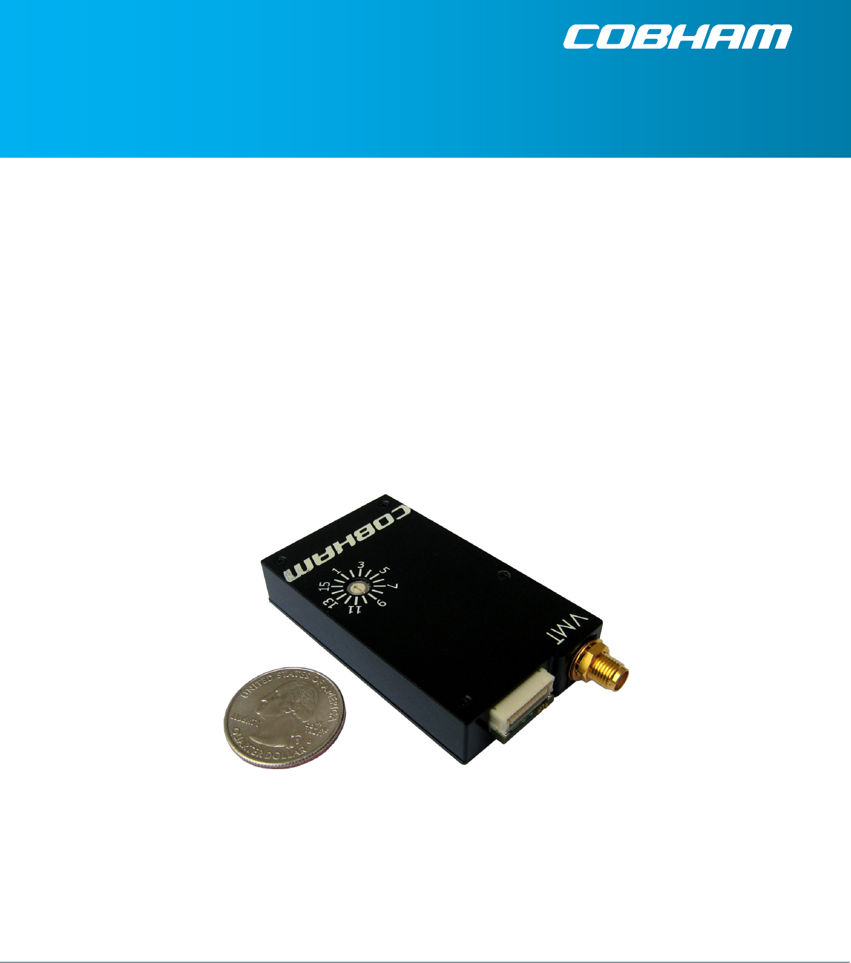
The VMT is a VETA Miniature Transmitter that has been designed to be as small and power efficient as
possible. It is an ideal fit for concealment and body worn applications and small-unmanned vehicles.
The VMT accepts a composite or S-Video Input, Analog Stereo Audio Inputs (with MIC Bias) and a
RS232 User Data Input. There is also an option to accept SDI Video. The Video is compressed according
to MPEG-2 or MPEG-4 (Optional) specifications. The Audio is sampled and compressed. The Audio,
Video and Data packet streams are multiplexed with basic service data to indicate the service name.
The stream can be scrambled with a simple fixed key scrambling system (ABS standard) to give basic
protection in sensitive applications. Additional security is accomplished with the optional AES
scrambling system. The transport stream is sent for FEC pre-processing and COFDM modulation. The
modulated signal is amplified and output through a SMA-F connector.
This manual provides information on how to operate the VMT (VETA Transmitter) as well as pertinent
technical information related to the overall system.

100-M0169X1 11-15-11
10 of 24
www.cobham.com/gms
4.1 Key System Features
• COFDM Modulation : 2K or 400
(1)
Carriers
• Bandwidths: 6 MHz, 7 MHz or 8 MHz
(1.25 & 2.5 MHz optional)
• Output Frequency: 2412-2472MHz
• Output Power: 100mW
• Built-in MPEG-2/MPEG-4
(2)
Encoder
• Low End to End System Latency
(3)
(down to ~44mS)
• Rugged Compact Design: 2.7” x 1.6” x 0.5” (6.9cm x 4.0cm x 1.3cm)
• Secure – ABS and AES 128/256
(4)
(1)
400 carriers is optional with the 1.25 or 2.5MHz RF bandwidth upgrades
(2)
MPEG-4 is optional and included with the 1.25MHz upgrade. MPEG4 optionally used in 1.25MHz and 2.5MHz modes.
(3)
With DVB-T standard BWs. ~120mS system latency in 1.25 & 2.5 MHz Bandwidths depending on modulation
parameters
(4)
AES 128 or 256 bit encryption is optional
4.2 Warranty
GMS offers a 12-month standard product warranty. During this period, should the customer encounter
a fault with the equipment we recommend the following course of action:
If fault persists, call our support line and report the fault. If fault persists and you are informed
to return the product, please obtain an RMA number from the GMS support department or
website and ship the equipment with the RMA number displayed and a description of the fault.
Please email the support section the airway bill/consignment number for tracking purposes.
Depending on the nature of the fault, GMS endeavor to repair the equipment and return it to the
customer within 14 days of the item arriving at our workshops. Obviously, it is impossible to cater for
all types of faults and to manage 100% replacement part availability, and delays are sometimes
inevitable.
Please contact GMS for details of packages that can be tailored to meet your individual needs,
whether they are service availability, technical training, local geographic support or dedicated spares
holdings.
4.3 Safe Operating Procedures
• Ensure that the power supply arrangements are adequate to meet the requirements of VETA
product.
• Operate within the environmental limits specified for the product.
• Only authorized, trained personnel should open the product. There are no functions that
require the User to access the product’s interior.
100-M0169X1 11-15-11
11 of 24
www.cobham.com/gms
5.0 General System Information
5.1 Getting Started
The Standard VMT kit includes the following items:
• VMT Unit
• VMT Breakout Cable (GMS p/n 780-C0449*)
(Power, Composite Video, Audio , RS232 Control)
NOTE: Based on customer applications GMS can deliver a receiving system, additional cables and
antennas. Contact GMS for further information
The VMT is pre-configured by GMS prior to shipment (based on customer requirements), thus is ready
to work “right out of the box”.
5.2 Initial Checkout
Prior to installing a VMT into the desired target environment, an initial checkout should be performed
to ensure proper operation of the unit. The initial checkout described below consists of configuring a
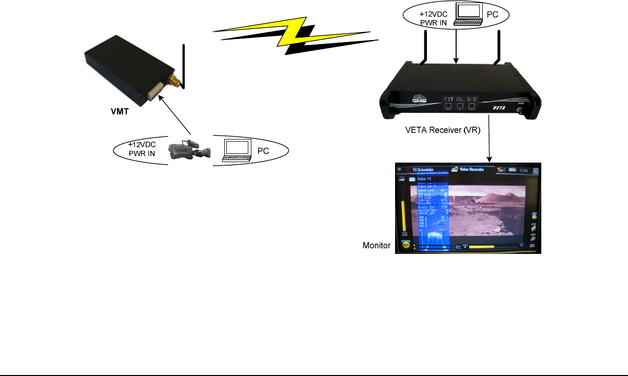
basic VETA Digital Link (VDL). In the case outlined, we will assume a VETA Receiver (VR) is used to
receive the VMT. Note, that any DVB-T compliant receiver can be employed instead if the VMT is set-
up in standard DVB-T Mode (RF BW 6, 7, or 8 MHz) and not in ultra-low delay mode.
Figure 5.1 Basic VDL Setup

100-M0169X1 11-15-11
12 of 24
www.cobham.com/gms
The following setup can be done, either wirelessly with antennas, or through hard line connection
with 50Ω cable. In either case, make sure there is enough attenuation from the Tx to the Rx to
avoid overdriving the receiver. In most DVB-T receivers, their optimal input power ranges from -30
to -70 dBm. The VR shown has internal BDCC installed locally within unit, which is our standard VR
configuration.
5.2.1 Initial Checkout of VMT
• Install Omni-directional antennas (or ones best suited for the application) onto the RF IN A
and RF IN B ports on the VETA Receiver (or equivalent DVB-T Receiver) and one on the SMA
RF connector on the VMT transmitter. Note: As a rule, transmitters should not be powered on
without a load attached to the RF output connector.
• Attach the VMT standard breakout cable (or customer equivalent), 780-C0449* to the Tx.
Apply +12VDC to the red pigtail and GND to the black pigtail. Ensure power supply can supply
at least 0.4A at +12VDC (Note: The VMT can operate over 5.9-18VDC range).
• Attach a composite video source to the BNC video input cable that is located on the VMT
breakout cable. Make sure that the source video is powered on and outputting the video in
the desired format (PAL or NTSC) and input port (Composite #1 or #2 or SDI).
• Connect the RS232 Control of the VMT to the corresponding serial port of the PC. Open the
GMS configurator software (see VETA Miniature Transmitter
Software Manual, 100-M0130, for
control software details).
• If the TX receives the source video signal, the Video Locked Status indicator will show: “YES.”
If the Video Locked Status shows “NO,” check the connection of the Video source, verify that
the video source is indeed active, and click the “Query” button. Verify that the Video source
matches the “Video Input” selection. If the source is NTSC, then the VMT “Video Input” should
show “NTSC.”
• Next, note which VMT Configuration is active, 1 through 16 under the Load Config pull down
window. This number must match the receiver configuration, which assumes all
configurations have matching parameters. Also verify that the Output Mode shows “ON,”
otherwise the RF section of the VMT will be shutdown and no RF transmission will be
possible.
• This completes the initial setup of the VMT for Video transmission and RF testing.
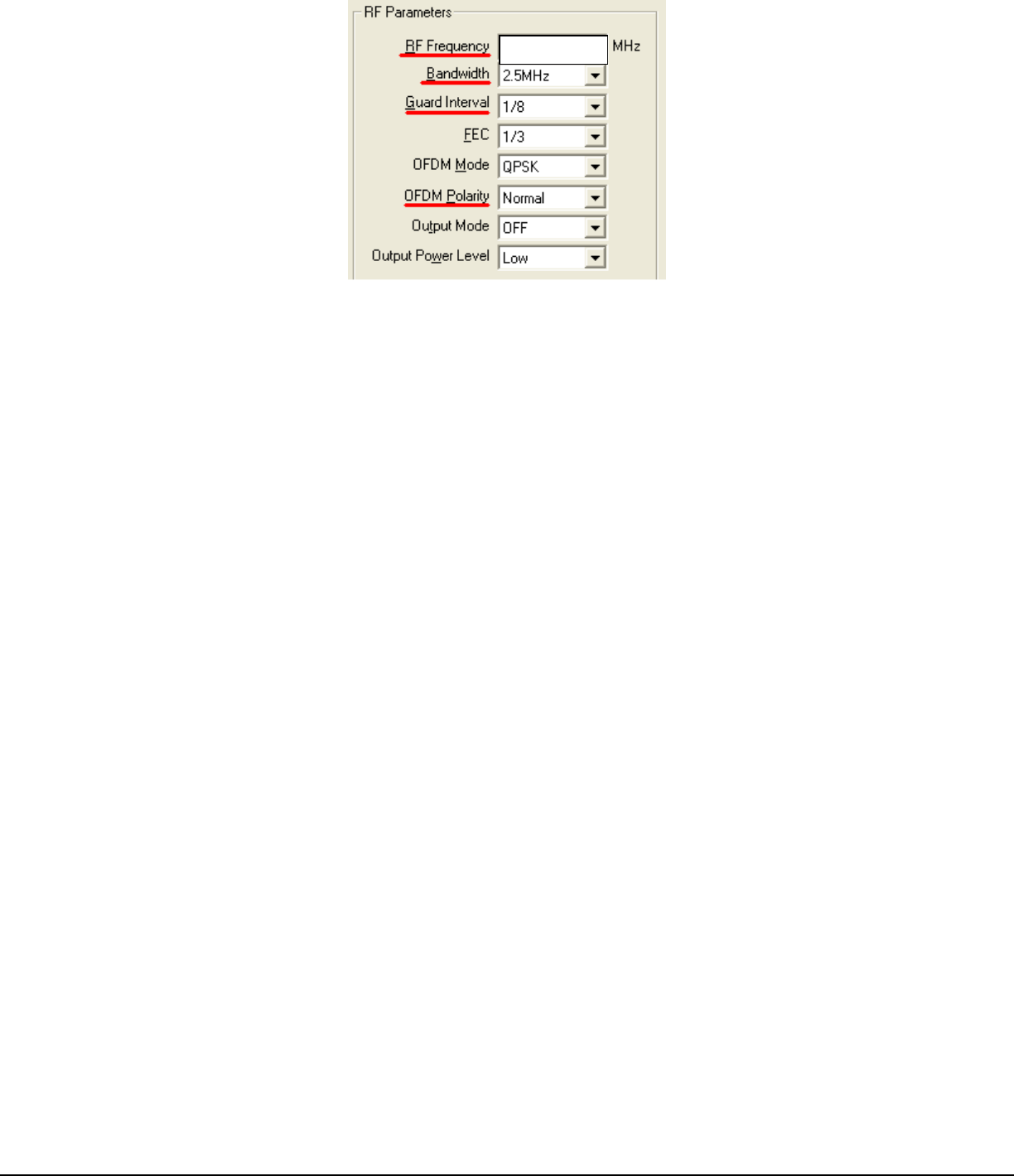
5.2.1.1 Key RF settings For COFDM Transmission
The RF settings shown in Figure 3.2 show the key COFDM configurations for setting up any
COFDM link. The settings underlined in RED must be matched specifically to the VETA
Receiver for proper RF lock and demodulation (the other COFDM parameters are auto-
detected). In general, when troubleshooting a RF link, the operator should make sure that
the following RF parameters are matched at both the Transmitter and Receiver.
100-M0169X1 11-15-11
13 of 24
www.cobham.com/gms
Figure 5.2 VMT RF Essentials
5.2.2 Setup of Corresponding VETA Receiver
• Attach a video cable from BNC VID output port on the VR (Veta Receiver) to the composite
input of the video monitor.
• Apply +12Vdc to the VR, pins 1, 2, +12V and 3, 4 ground to the J2 dB connector (if using
provided cable use the red (+12V) and black (GND) pigtails. Power supply must be able to
source 2 AMP at 12VDC.
• Turn on the video source and video monitor equipment.
• Turn on the VR with the PWR switch on the front panel (up is ON).
• Ensure the selected configuration matches that of the transmitter. If not, use the VETA
Receiver configurator to select or modify the configuration, see Figure 3.2 for VMT settings to
match to the VR.
• Once the VR has powered-up, ensure that the Config LED is light solid green. If not, press the
RF button on the front keypad (this action provides power to the internal down converters) so
that corresponding Config LED is solid green.
• Press the MODE button on the Front Panel to turn on the diagnostic OSD (on screen display)
for the video monitor.
• After approximately 5 seconds, the link should be established and video provided by the
source should be displayed on the monitor. On the Receiver side, the green RF LED should
light as well as the Signal Strength indicators. The OSD should show lock onto the incoming
signal with a corresponding power level and SNR on the two receive inputs.
• If the red Alarm LED lights it may be an indication that the receiver is unable to lock to a
signal. Check the following:
Ensure the receiver and transmitter have matching RF configurations, see Figure 3.2.
Ensure the transmitter Output Mode is “ON.”
If the TX and RX are physically too close to each other, the RX may overload causing
distorted Video. If the RF power sensed by the VR is greater than -20dBm, you may
want to reduce the power out of the TX (using RF attenuators) or physically move the TX
& RX further apart.
2412
.00

100-M0169X1 11-15-11
14 of 24
www.cobham.com/gms
Conversely, the power level to the VR may be too low for RF lock and demodulation. If
the RF power sensed by the VR is less than -80dBm, you may want to increase the RF
power to the VR. Either decrease the RF attenuation between the Tx and Rx or
physically move the two closer to one another.
The initial checkout described above is simply to check the basic video operation of the VMT unit.
For further details on the connectors, monitoring and controlling the VMT read thoroughly through
this manual.
100-M0169X1 11-15-11
15 of 24
www.cobham.com/gms
6.0 Hardware Overview
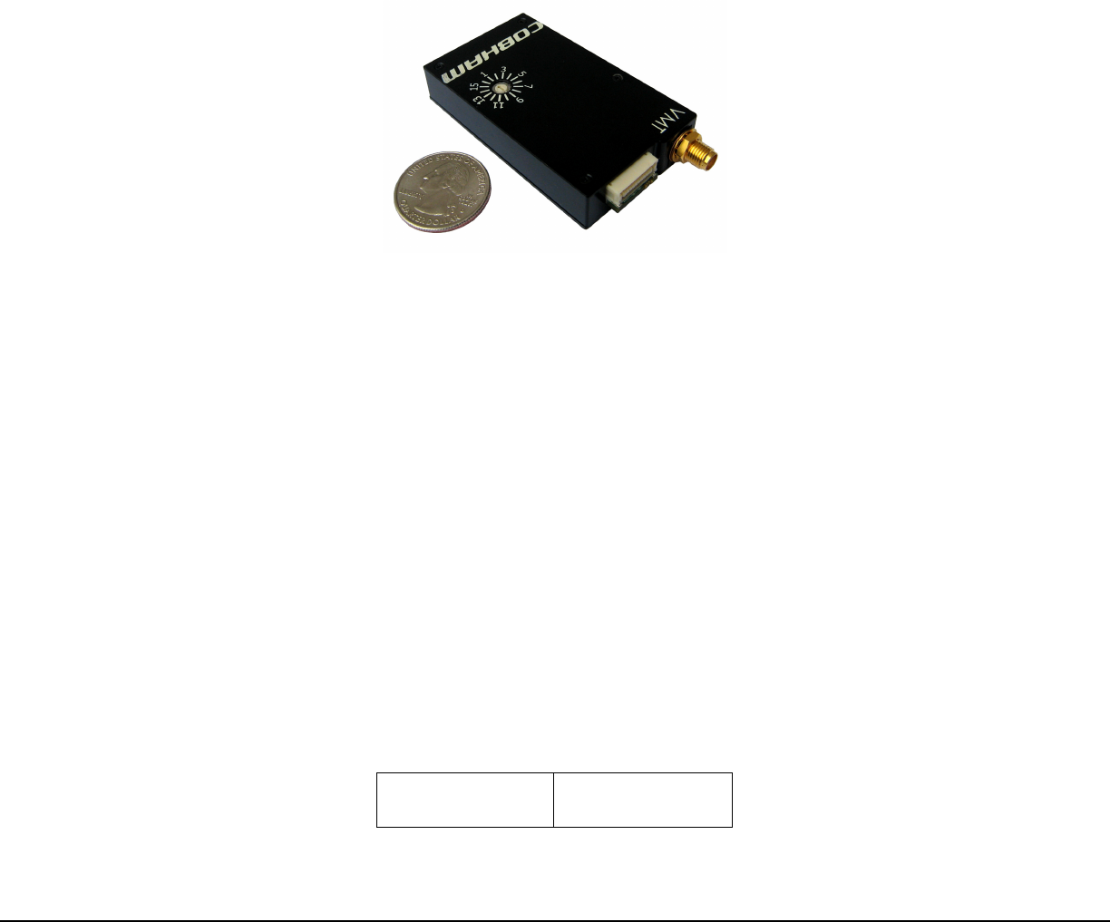
The VMT consists of a rotary switch along with interface connectors.
6.1 VMT Interface Connectors
The VMT interface connectors consist of a RF SMA, and a 21 PIN JST connector. They are described in this
section.
6.1.1 RF Out
The RF output consists of a female SMA connector.
Connector Type
Comments
SMA (F)
Antenna connects here
Table 1 RF Connector
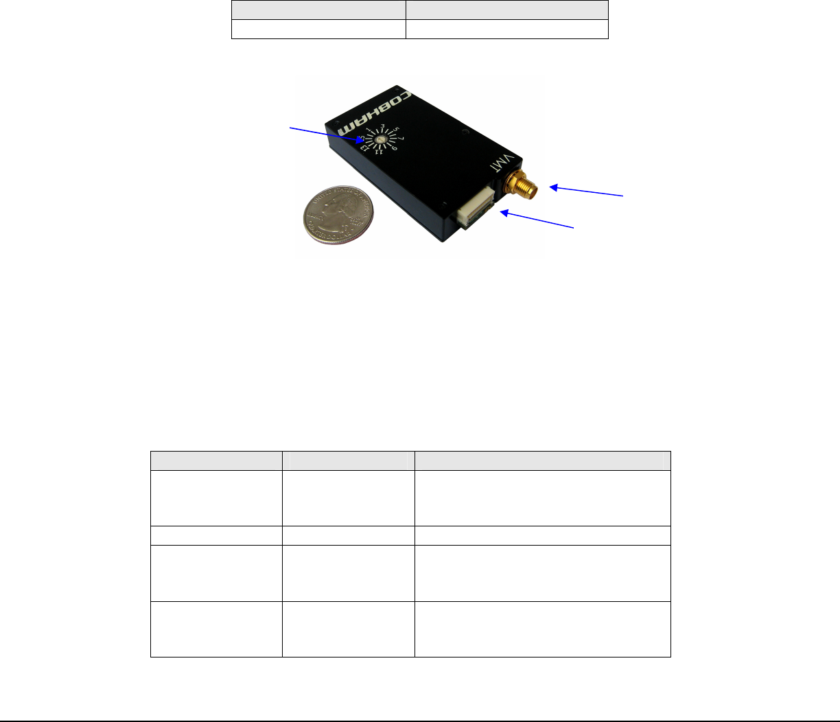
Figure 6.1 VMT Interface Connectors
6.1.2 I/O
The VMT ‘I/O’ connector is a dual row twenty one (21) pin JST, JST part number: SM21B-SHLVS-G-
TB(LF). A GMS breakout Cable, #780-C0449 is provided for testing. It is used to provide the
interface for external power, audio (with phantom biasing for Tibbetts microphones), analog video
and RS232 control. The pin out for the I/O connector is shown in Table 2 below.
PIN
SIGNAL
NOTES
1 SDI VIDEO IN
SD
-
SDI Video Input. This is an
optional upgrade. Must be selected
with GMS Control Software.
2
GND
GND
3 CHAIN CLK IN
N/C. Chaining used in
Repeater/Multiplexing applications,
contact GMS for details
4 CHAIN DATA IN
N/C. Chaining used in
Repeater/Multiplexing applications,
contact GMS for details
RF Out, Ant Port
I/O JST
-
21 Connector Pin Out
Rotary Switch

100-M0169X1 11-15-11
16 of 24
www.cobham.com/gms
PIN
SIGNAL
NOTES
5
AUDIO GND
AUDIO GND
6 COMP INPUT 1
Composite Video Input. Must be
selected with GMS Control Software.
Also used for S-VIDEO Input.
7 COMP INPUT 2
N/C.
Only used for S
-
VIDEO Input.
Must be selected with GMS Control
Software.
8
GND
GND
9
AUDIO LEFT
Audio Left, W/ 2V Phantom Bias
.
10
AUDIO RIGHT
Audio Right, W/ 2V Phantom Bias
.
11
GND
GND
12 CHAIN CLK OUT*
N/C.
Chaining used in
Repeater/Multiplexing applications,
contact GMS for details
13 CHAIN DATA
OUT*
N
/
C.
Chaining use
d in
Repeater/Multiplexing applications,
contact GMS for details
14
GND
GND
15
RS232_DATA_Rx
N/C. RS232 for User Data, Rx
16
RS232_DATA_Tx
N/C. RS232 for User Data, Tx
17
RS232_CNTRL_Rx
RS232 for PC CONTROL Software
18
RS232_CNTRL_Tx
RS232 for PC C
ONTROL Software
19
2.8V uC
N/C. 2.8V Output from Unit
20
GND
GND
21
VBATT_IN
Input Power to Unit: 5.9
-
18VDC
Table 2 JST Connector (21 Pins)
Note: Table 2 references Cable 780-C0449. GMS can build customized cables to
customer specifications to access functionality not included in our standard cable.
Customers can also choose to build their own cables. Contact GMS with any questions.
6.1.2.1 Phantom Bias for TIBBETTS Microphones
The VMT does not provide a traditional separate bias voltage for surveillance microphones.
Instead, we provide a 2V Microphone BIAS directly on the signal lines. This is called phantom
biasing of microphones and has been proven to work with TIBBETTS 151/251/351 series
microphones by GMS. See TIBBETTS technical application notes for Phantom powered 2-
wire connection for specific details, GMS standard breakout cable employs 2-Wire Option C.
This wiring is in accordance with section 4.9.2 of RFP: E007216R and Attachment A of RFP:
E007216R.
In addition, to note, single ended line level audio can also be used instead of microphones.
The user will want to lower the Audio Gain to “0dB” through the GMS control software when
Line level audio is input.
100-M0169X1 11-15-11
17 of 24
www.cobham.com/gms
6.2 Local Control
6.2.1 Set-Up Group Select Switch
How to Operate
There is one 16 position external rotary switch mounted into the chassis for the VMT
(reference Figure 6.2)
Figure 6.2 VMT with Rotary Switch
The switch is used to control set-up group selection. Set-up group selection can also be
controlled through GMS control software configurator GUI (refer to the Software Manual,
100-M0143).
As previously stated, administrators define the set-up groups for specific applications. Each
set-up group completely defines all of the transmitter’s set-up parameters including center
frequency, output RF power level, modulation parameters, video, audio, user data and
encryption. Each set-up group can be completely different from any other group. Field
personnel will select specific set-up groups via pre-determined guidance from the
administrators. Matching the transmitter operation to the receiver operation is as simple as
selecting the same set-up groups. For example: If the transmitter is set to preset #4, then
the receiver needs to be set to preset #4 for them to operate together.
The Rotary Switch is in Hexadecimal format, representing the 16 configurations. While the
switch is in hexadecimal the control software is shown in decimal format, see Table 3.
Because the switch is in binary format, the first setting begins at zero.
Rotary Switch
Position
Configuration #
(Decimal Value)
100-M0169X1 11-15-11
18 of 24
www.cobham.com/gms
Rotary Switch
Position
Configuration #
(Decimal Value)
0 1
1 2
2 3
3 4
4 5
5 6
6 7
7 8
8 9
9 10
A 11
B 12
C 13
D 14
E 15
F 16
Table 3 Rotary Switch Configurations
7.0 Remote Control of VMT
The VMT can be configured with GMS’ RS232 VETA Remote Control Unit (VRCU).
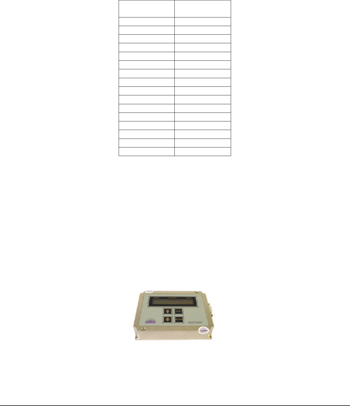
7.1 VETA Remote Control Unit – VRCU
In addition to being able to select a set-up group by using the rotary switch on the VMT, a RCU,
remote control unit, is available. The RCU is a small hand–held remote control unit designed for
serial control of the VMT transmitter. It allows the operator to access all features of the transmitter
on a two-wire RS-232 connection. For details, see the on-line manual: 100-M0104.
Figure 7.1 VETA Remote Control Unit

100-M0169X1 11-15-11
19 of 24
www.cobham.com/gms
8.0
Software Overview
Configuration, control and monitoring of the VMT units are done by using GMS’ MS Windows-based
VMT Configurator software program 100-SW0070. This Graphical User Interface (GUI) program
provides the end user with a straightforward way to interface with the VMT unit. During normal
operation, once a link is established, the VMT Configurator GUI does not need to be active and can be
disconnected from the VMT unit.
Refer to the Software Manual, 100-M0143, for further information.

100-M0169X1 11-15-11
20 of 24
www.cobham.com/gms
9.0 VETA Chaining Feature
The VETA series of products use a Proprietary Transport stream protocol called ‘Chaining’ to create the
VDR (VETA Digital Repeater), the CSM (Compact Surveillance Modem) or a UDP Tx. This is all available by
utilizing the chaining feature that comes standard on all VETA Tx, VR and VNA. Contact the factory for
more information about the Chaining feature and the variety of applications it can be employed with.
9.1 VETA Digital Repeater (VDR)
An In band or cross band repeater can be made very simply with the VETA series Transmitter
(VT-2W, VT-C, VT-L, or VMT) in conjunction with a VETA Receiver (VR). The user simply has to
connect the ‘Chaining Out’ of the VR into the ‘Chaining In’ of a VETA Tx.
9.2 Compact Surveillance Modem (CSM)
The VETA Compact Surveillance Modem is much like the VDR with the addition of the VETA
NETWORK ADAPTOR (VNA). The VNA allows for IP streaming of video, or with a complement
CSM a LAN Bridge (CSB) can be created across the link.
9.3 UDP Transmitter
A UDP transmitter can easily be employed using the Chaining Out of a VNA into the Chaining In
of a VETA Tx. UDP can be sent to the VNA via the RJ45 connector that is converted to Chaining
within the VNA and delivered to the VETA Tx through the Chaining interface. On the receiver
Side, a VR will send its Chaining Out to the Chaining In of a VNA. The VNA can be connected to a
router or simply another computer to distribute the UDP data.

100-M0169X1 11-15-11
21 of 24
www.cobham.com/gms
10.0 Specifications
10.1 COFDM RF Output
Output Frequency: 2412-2472MHz (ISM Band)
Bandwidth: Selectable 6, 7, 8 MHz (1.25 & 2.5 MHz Optional)
RF Output Power: Programmable up to 100 mW
Connector: SMA-F
Frequency Stability: +/-2 ppm,
Output Impedance: 50Ω, unconditionally stable, open & short circuit protected
Harmonics: <-25 dBm
10.2 Modulation
Modulation Type: COFDM 2K: QPSK, 16QAM
FEC: 1/2, 2/3, 3/4, 5/6, 7/8
Guard Intervals: 1/32, 1/16, 1/8, 1/4
Optional Narrow Band (1.25 & 2.5 MHz BW)
Modulation Type: C-OFDM 400: QPSK, 16QAM
FEC: 1/3, 2/3,
Guard Intervals: 1/16, 1/8
Spurious > 52dBc
10.3 Video Encoding
Video Input: Composite, S-Video
Standards: NTSC or PAL
SDI option available
Compression Standard: MPEG-2 or MPEG-4
Chrominance Profile: 4:2:0 or 4:2:2
Line Standard: 525 and 625
Horizontal Resolution: 704, 528, 480 or 352 pixels
Vertical Resolution: 576 (625 line) and 480 (525 line)
Systems Latency end to end delay: Down to ~40 ms
10.4 Audio Encoding
Analog Audio Inputs:
Dual, Line Level or Mic Level, Single Ended, Clip Level 12 dBm
(Mic connection via breakout cable)
Compression Type: MPEG or NICAM (User Selectable)
NICAM AUDIO
Bits per Sample: 12 or 8
Sampling Frequency: 32 KHz, 16 KHz or 8 KHz
MPEG AUDIO
Compression Standard: ISO/IEC 13818-3
Bit rates: Up to 448 kbit/s/ch
Sampling Frequency: 32 kHz or 48KHz
Mic Bias: 2V

100-M0169X1 11-15-11
22 of 24
www.cobham.com/gms
10.5 RS232 Data Input
Baud Rate: Up to 115 KBaud.
10.6 Security Option
ABS is standard. The VMT can optionally be provided with Advanced Encryption System (AES)
128/256 for protecting the signal in sensitive applications.
10.7 Physical
Dimensions: 1.6” wide x 2.7” long x 0.5” high
4.0 cm x 6.9 cm x 1.3 cm
Weight: 0.114 lbs
52 grams
10.8 Environmental
Operational Temperature: -20 to 70 deg C
Humidity: Up to 95% non-condensing
10.9 DC Power
DC Voltage Range: 5.9 V - 18 V
Reverse Polarity Protection up to 30 V
Power Consumption: Depends on Frequency, typical =4.1W
10.10 Antenna Description
Type: Directional Antenna
Gain: 2 dBi
GMS part # AOS2A02N360FG
10.11 Control
Local – Easy to use Rotary Switch allows up to 16 user-defined operating modes covering most
programmable parameters.
Connector - DB-9 (F), RS232 control.
100-M0169X1 11-15-11
23 of 24
www.cobham.com/gms
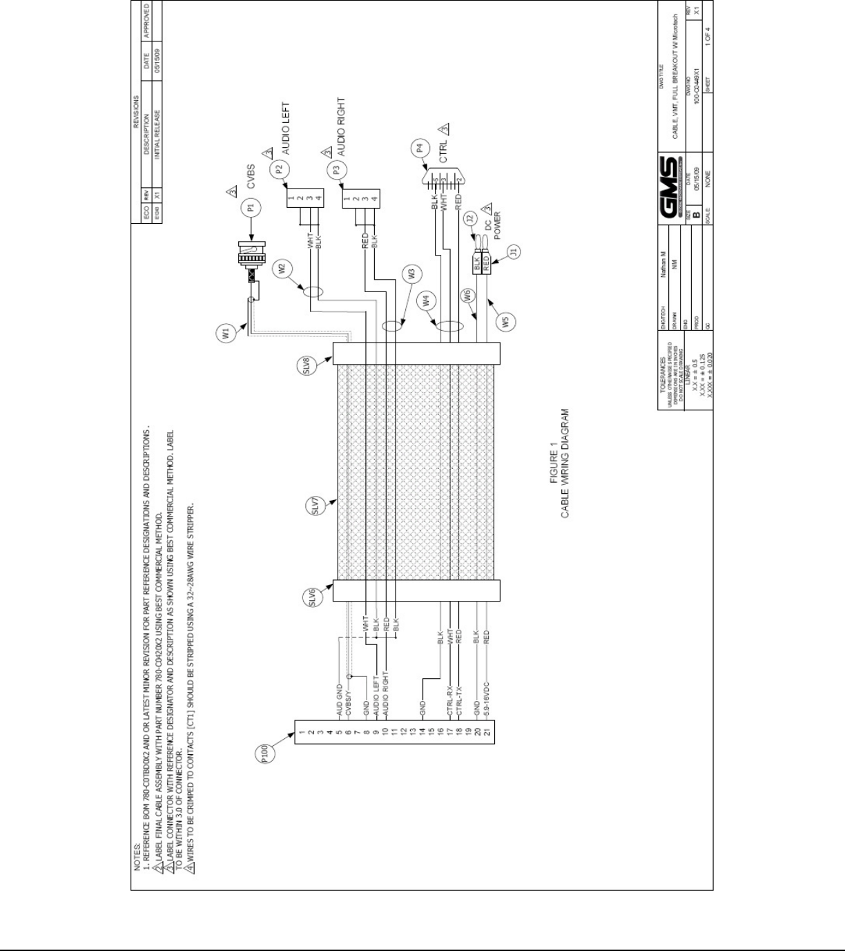
Appendix A: Standard Breakout Cable