Global Sun Technology AP-DS11 Access Point 11Mbps User Manual users manual
Global Sun Technology Inc Access Point 11Mbps users manual
users manual
G
GL
L2
24
41
11
1A
AP
P
Access Point
Version:1.0 Date:2000/10/04
1
FCC Information
This equipment has been tested and found to comply with the limits for a Class A digital device
pursuant to part 15 of the FCC Rules. These limits are designed to provide reasonable protection
against harmful interference when the equipment is operated in a commercial environment.
This equipment generates, uses, and can radiate radio frequency energy and, if not installed and
used in accordance with the instruction manual, may cause harmful interference to radio
communication.
Operation of this equipment in residential area is likely to cause harmful interference in which
case the user will be required to correct the interference at this own expense.
The user should not modify or change this equipment without written approval of the company.
Modification could make invalid any authority to use this equipment.
It is unsafe to work under circumstances in which the RF exposure exceeds recommended
amount. To prevent the situation happening, people who work with the antenna should be
aware of the following rules:
1. Install the antenna so that a 20 cm distance can be kept from the antenna.
2. While installing the antenna in the location, please do not turn on the power of the wireless
card.
3. While the device is working, please do not contact the antenna.
This device complies with Part 15 FCC Rules. Operation is subject to the following two
conditions: (1) This device may not cause harmful interference. (2) This device must accept any
interference received including interference that may cause undesired operation."
2
Contents
SECTION 1 ABOUT GL2411AP-0A ACCESS POINT...............................3
INTRODUCTION ................................................................................................................................................3
1-1 FEATURES...................................................................................................................................................3
1-2 FIRMWARE FUNCTIONALITY.............................................................................................................3
1-3 APPLICATIONS..........................................................................................................................................4
1-4 PRODUCT KIT...........................................................................................................................................4
SECTION 2 HARDWARE INSTALLATION........................................................6
2-1 EQUIPMENT REQUIREMENT.............................................................................................................. 6
2-2 GL2411AP-0A HARDWARE INSTALLATION............................................................................6
2-3 SOFTWARE LIMITATION.......................................................................................................................6
SECTION 3 HOW TO CONFIGURE GL2411AP-0A ACCESS
POINT..................................................................................................................................................................7
3-1 INSTALLTION GL2411AP-0A AP BY USB CABLE FOR WINDOWS 98..................... 7
3-2 GL2411AP-0A AP UTILITY SETUP..........................................................................................10
DFU (USB Configuration Utility) .....................................................................................................................10
SNMP Configuration Utility.............................................................................................................................. 12
3-3 GL2411AP-0A AP CONFIGURATION UTILITY....................................................................14
DFU (USB Configuration Utility) .....................................................................................................................14
SNMP Configuration Utility.............................................................................................................................. 16
APPENDIX A NETWORK CONFIGURATION.............................................19
A-1 NETWORK TOPOLOGY......................................................................................................................19
Ad-Hoc Mode.....................................................................................................................................................19
Infrastructure.....................................................................................................................................................19
A-2 ROAMING................................................................................................................................................20
APPENDIX B SPECIFICATIONS..................................................................................21
APPENDIX C GLOSSARY.....................................................................................................22
3
Section 1 About GL2411AP-0A Access Point
Introduction
The GL2411AP-0A (11 Mbps WLAN Access Point) is a long-range, high performance LAN product,
which provides Access Point services to a 2,4 GHz RF network and bridges to an Ethernet backbone. The
design of this product is based on AT76C510 (bridge-on-a-chip) module, a highly integrated ASIC designed
to combine legacy LANs with wireless LANs. AT76C510 performs all the necessary inter-networking and
bridging functions. It receives data from both networks, stores them locally for further processing, installs and
maintains connections and transmits the packets to the proper destination. Furthermore, AT76C510 interfaces
three more modules, the Ethernet PHY, the wireless PHY and the RAM modules, for allowing compact
system implementation and flexibility for supporting almost all the possible physical interfaces.
1-1 Features
– Glueless connection to Intersil PRISMI, PRISMII Direct Sequence Spread Spectrum (DSSS) radio chip
set. Able to communicate also with other DSSS radios
– Supports 11 Mbps rates with automatic fallback to 5.5, 2 and 1 Mbps
– WEP encryption/decryption is accomplished on the fly
– Ethernet MAC supports MII interface and 10/100Mbit speeds
– Hardware modules for Packet Filtering and statistics gathering
– Glueless SRAM, Flash interface for data buffering and program storage, supporting up to 16 MB of
memory
– Integrated 2 x 6K x 32 bit internal SRAM modules for fast 32-bit program execution and temporary
storage of data
– Supports 3V supply
– 128-pin PQFP, TQFP
– JTAG Boundary Scan (IEEE 1149.1) test access port for board-level production test
1-2 Firmware functionality
The firmware functionality of the bridge supports:
1. Distributed Coordination Function (DCF )
CSMA/CA
Backoff procedure
4
NAV management
ACK procedure
Retransmission of unacknowledged frames
2. RTS/CTS handshake
3. Duplicate detection and recovery
4. Fragmentation and Reassembly
5. Beacon generation
6. Probe response
7. Wired Equivalent Privacy Algorithm (WEP)
8. Authentication Algorithm (Open System, Shared Key)
1-3 Applications
The Serial of LAN products offer a fast, reliable, cost-effective solution, allowing clients to wirelessly
access the network in applications such as following:
1. Remote access to corporate network information
E-mail, file transfer and terminal emulation
2. Difficult-to-wire environments
Historical or old buildings, asbestos installations, and open area where wiring is difficult to employ
3. Frequently changing environments
Retailers, manufacturers and banks who frequently rearrange the workplace and change location
4. Temporary LANs for special projects or peak time
Trade shows, exhibitions and construction sites need temporary setup for a short time period. Retailers,
airlines and shipping companies need additional workstations for a peak period. Auditors require
workgroups at customer sites.
5. Access to database for mobile workers
Doctors, nurses, retailers, white-collar workers need access to database while being mobile in the hospital,
retail store or office campus.
6. SOHO (Small Office and Home Office) users
SOHO users need easy and quick installation of a small computer network.
1-4 Product Kit
! GL2411AP-0A ……………………………………………...……….x 1
! Antenna (fixed)………………………………………………………x 2
5
! GL2411AP-0A driver and utility CD…….…………………...…...x 1
! A/C Power Adapter…………………………………………………x 1
! USB cable…………………………………………………………….x 1
If any of the listed items are not included or found damaged, please contact your local dealer.
6
Section 2 Hardware Installation
2-1 Equipment Requirement
Installation of GL2411AP-0A requires:
1. An A/C power outlet (100~240V,50~60Hz) which will supply the power for the GL2411AP-0A Access
Point
2. A 10/100 Base-T (UTP) Ethernet cable drop (RJ-45 connector)
2-2 GL2411AP-0A Hardware Installation
Please follow these procedures while setting up the hardware:
1. Site Selection
Choose a proper place for your GL2411AP-0A.
In general, the best location to place your GL2411AP-0A is the center of your wireless coverage, with line
of sight to all your mobile stations.
2. Adjust the direction of the Antenna
Adjust the direction of the antenna placement to improve the GL2411AP-0A’s performance. Try to place
the antenna in the position which can best cover its BSS. Normally, the higher you place the antenna, the
better the performance will be. The character of diversity enhances the receiving sensitivity.
3. Connect the Ethernet Cable
GL2411AP-0A can be connected to the 10/100 Base-T Ethernet network. Connect your UTP Ethernet cable
to the RJ-45 connector of the GL2411AP-0A AP and connect the other side of UTP Ethernet cable to a hub.
4. Connect the Power Cable
Connect the power adapter cable to the DC5V Power Socket of the GL2411AP-0A. ONLY use the power
adapter supplied with the GL2411AP-0A. Otherwise, the product may be damaged.
2-3 Software Limitation
1. DFU Software
Operation System:
Chinese Windows 98/2000/ME, English Windows 98/2000/ME
2. SNMP Software
Operation System:
English Windows 98/NT/ME
7
Section 3 How to Configure GL2411AP-0A Access Point
The GL2411AP-0A can be configured by DFU utility for only Windows® 98. You need plug the USB
cable with the GL2411AP-0A and the USB slot of the PC to run DFU.exe for configuring the GL2411AP-0A
and setting the setup.
3-1 Installation GL2411AP-0A AP by USB cable For Windows 98
1. Because the utility is only for Windows® 98 at this moment, you must boot your PC into Windows® 98.
2. Run DFUzip.exe in GL2411AP-0A Access Point driver and utility disk to decompress the files into
C:\DFU.
3. Ensure you have followed the procedure as described in the previous section to finish hardware installation.
4. Plug the two sides of the USB cable into the USB slots of GL2411AP-0A and your PC.
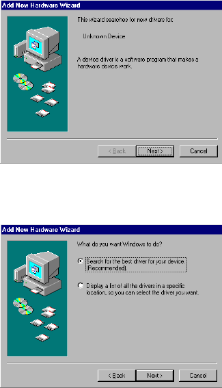
5. Windows® 98 will automatically detect the GL2411AP-0A and prompt you to install the necessary driver.
Click “Next” to begin the installation.
6. Select “Search for the best driver…” and click “Next”.
8
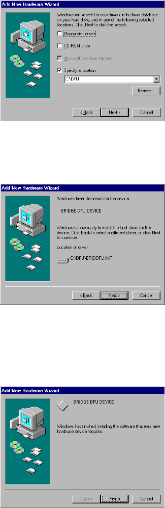
7. Select “Specify a location” and click “Browse”. On the windows information dialog, double-click the
“C:\DFU” folder icon from the list and Windows® 98 will automatically enter the path. Then click “Next”.
8. Windows® 98 will then acknowledge that it has found the appropriate driver and click "Next".
9. Windows® 98 will install the driver. As the driver files are being copied to the appropriate location, you
will be prompted to insert the Windows® 98 CD.
NOTE: You must insert the Windows 98®CD as the driver installation requires special files that will not be
available even if you have stored a copy of Windows® 98 source on your hard drive.
10. After Windows® 98 has finished installing the appropriate files, click “Finish”.
9
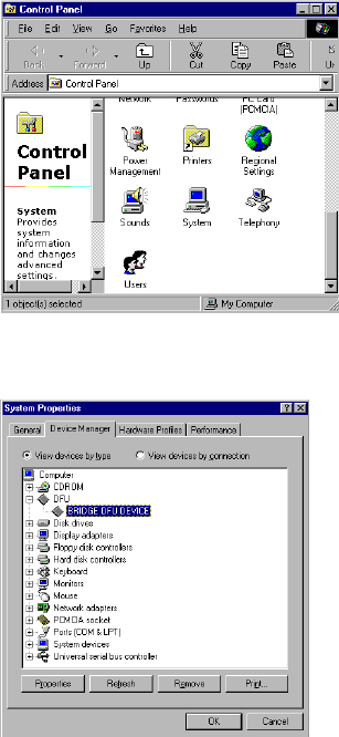
11. From the Control Panel, double-click the “System” icon.
12. From the “Properties” menu, please select the “Device Manager” tab. And check that the “BRIDGE
DFU DEVICE” device works fine.
10
3-2 GL2411AP-0A AP Utility Setup
DFU (USB Configuration Utility)
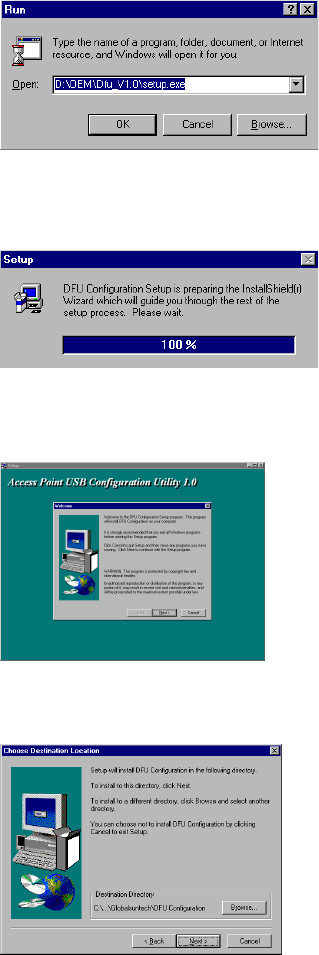
To setup the utility, please click the “Start” icon and then “Run”.
1. Please type “D:\OEM\Dfu_V1.0\setup.exe.” or use browse the file in the dialog box. Then click “OK” to
start the setup. (ps: D: is your CD-ROM driver)
2. In Computer screen will show this dialog, please wait for screen change.
3. Please click “Next” for further running.
4. Please browse the file shown in the dialog box, then click “Next”
11
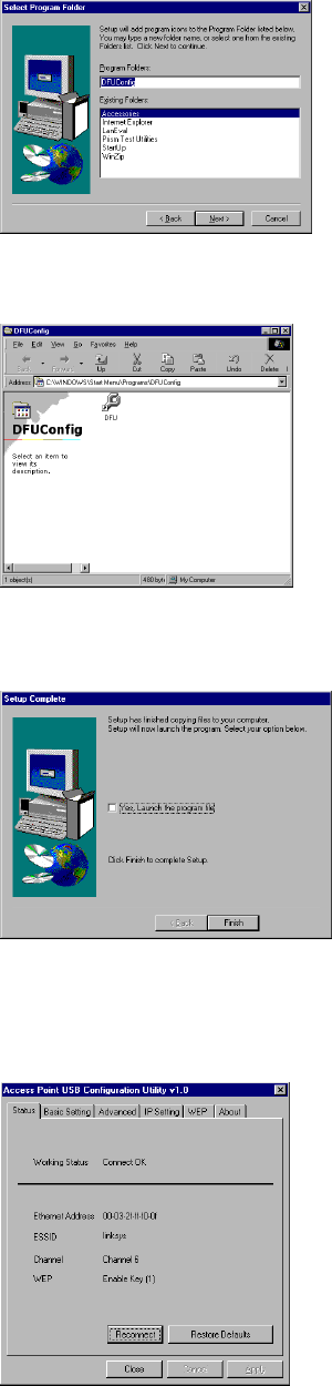
5. Setup will add program icon to the program folder shown as blow, then click “Next” for further setup.
6. Please click “DFU Config” folder for installation of USB configuration Utility.
7. After the installation of utility, please click “Finish”.
8. If you would like to configure the parameter, please click the page you want to change parameter. If not,
please just click “Close” to finish the setup.
12
SNMP Configuration Utility
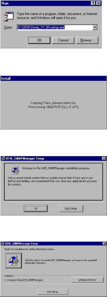
To setup the utility, please click the “Start” icon and then “Run”.
1. Please type “D:\OEM\SNMP_V1.3A\setup.exe.” or use browse to select the file in the dialog box. Then
click “OK” to start the setup. (ps: D: is your CD-ROM driver)
2. In Computer screen will show this dialog, please wait for screen change.
3. Please click “OK” for further running.
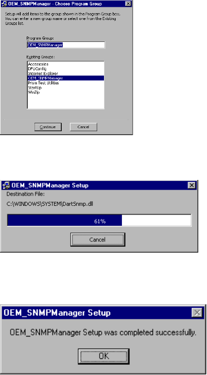
3. Please browse the file shown in the dialog box, then click the graphic icon
13
5. Please click “OEM_Manager” program Group for installation of SNMP configuration Utility.
And press “Continue” Button for next step.
6. Wait for screen change.
7. After the installation of utility, please click “OK”.
14
3-3 GL2411AP-0A AP Configuration Utility
DFU (USB Configuration Utility)
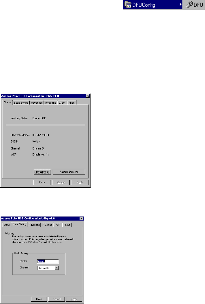
1. Click “Start” then, “Program” folder, you will find icon
please press icon “DFU” to execute program.
2. Page “Status” will show the DFU status including “Ethernet Address ”, ”ESSID”, ”Channel” and ”WEP”
Click “Reconnect” Button will reconnect AP and reread the parameter
Click “Restore Defaults” Button will restore the default value.
Click Page “Status” “Basic Setting” “Advanced” “IP Setting” “WEP” “About” to change other function.
If you had changed any configuration, click the “Apply” Button will become active.
3. Page “Basic Setting”, you can change ESSID and Channel
15
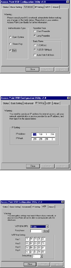
4. Page “Advanced”, you can change “Authentication Type” “Preamble Type” and “Basic Rate”
5. Page “IP Setting”, you can change “IP Address” and “IP Mask”
6. Page “WEP”, you can change “WEP Key Setting” if WEP is Enabled.
And you can use passphrase to generate the key.
16
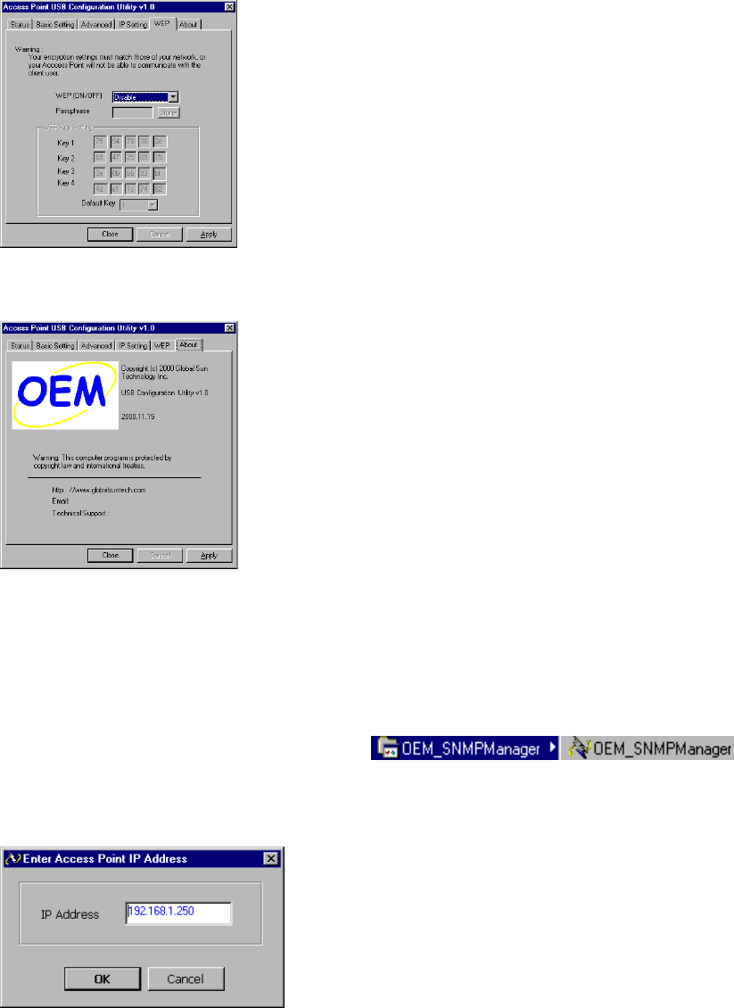
7. Page “WEP”, you can not change anything if WEP is disable.
8. Page “About” is our trademark and description.
SNMP Configuration Utility
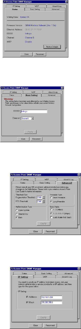
1. Click “Start” then, “Program” folder, you will find icon
, please press icon “OEM_SNMPManager” to execute program.
2.Please key in “IP Address” for your AP. (Default IP: 192.168.1.250)
3. Page “Status” will show the SNMP status including “Ethernet Address”, ”ESSID”, ”Channel”, ”WEP”
Click “Reconnect” Button will reconnect AP and reread the parameter
Click “Restore Defaults” Button will restore the default value.
Click Page “Status” “Basic Setting” “Advanced” “IP Setting” “WEP” “About” to change other function.
17
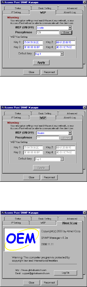
2. Page “Basic Setting”, you can change ESSID and Channel.
( The Apply button will be enabled, if you change any data on this page)
3. Page “Advanced”, you can change “Authentication Type” “Preamble Type” and “Basic Rate”
( The Apply button will be enabled, if you change any data on this page)
4. Page “IP Setting”, you can change “IP Address” and “IP Mask”
( The Apply button will enable if you change data on this page)
18
6. Page “WEP”, you can change “WEP Key Setting” if WEP is Enabled.
And you can use passphrase to generate the key.
( The Apply button will be enabled, if you change any data on this page)
7. Page “WEP”, you can not change anything, if WEP is disable.
8. Page “About” is our trademark and description.
19
Appendix A Network Configuration
A-1 Network Topology
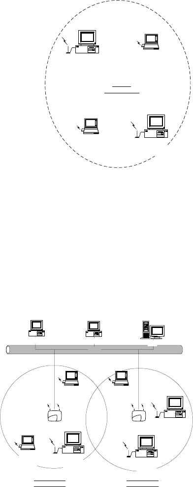
Ad-Hoc Mode
Fig. 1 - Ad-Hoc Wireless LAN
An Ad-Hoc wireless LAN is a group of computers, each equipped with one LAN adapter, connected as
an independent wireless LAN. Computers in a specific Ad-Hoc wireless LAN must be configured at the
same radio channel and ESSID.
Ad-Hoc wireless LAN is applicable at a departmental scale for a branch or SOHO operation.
Infrastructure
Fig. 2 An Example of Infrastructure Wireless LAN
Desktop PC
with
GL241101
Desktop PC
with
GL241101
Notebook
with
GL241101
Notebook
with
GL241101
Ad Hoc
Wireless LAN
Ethernet
Desktop PC with ethernet Desktop PC with ethernet Sever
GL2411AP-0A GL2411AP-0A
Notebook
with
GL241101
Notebook
with
GL241101
Notebook
with
GL241101
Desktop PC
with
GL241101
Desktop PC
with
GL241101
Desktop PC
with
GL241101
Infrastructure
Wireless LAN Infrastructure
Wireless LAN
20
GL2411AP-0A provides access to a wired LAN for wireless workstations. An integrated wireless and
wired LAN is called an Infrastructure configuration. A group of LAN PC users and a GL2411AP-0A
Access Point construct a Basic Service Set (BSS). Each LAN PC in the BSS can talk to any computer in
the wired LAN infrastructure via the GL2411AP-0A Access Point.
Infrastructure configuration not only extends the accessibility of a LAN PC to the wired LAN, but also
doubles the effective wireless transmission range for 2 LAN PCs. Since GL2411AP-0A is able to
forward data within its BSS, the effective transmission range in an infrastructure LAN is doubled.
BSS ID is, in essence, the ID of each independent GL2411AP-0A. All LAN PCs configured without
roaming options in the independent BSS must be configured with the BSS ID of the GL2411AP-0A.
Infrastructure is applicable in an enterprise scale for wireless access to central databases, or wireless
access for mobile workers.
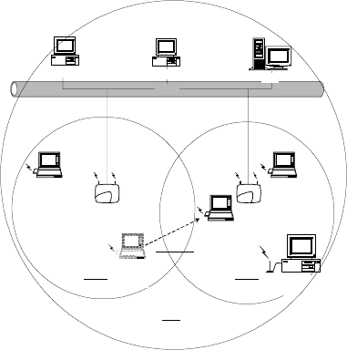
A-2 Roaming
Fig. 3 Roaming in an Extended Service Set (ESS)
An Infrastructure configuration also supports roaming capability for mobile workers. More than one BSS
can be configured to be an Extended Service Set (ESS). On account of a continuous connection to the
network, users within an ESS can roam freely. All LAN PCs and GL2411AP-0As within one ESS must be
configured with the same ESS ID and at the same radio channel.
Ethernet
Desktop PC with ethernet Desktop PC with ethernet Sever
GL2411AP-0A GL2411AP-0A
Notebook
with
GL241101
Notebook
with
GL241101
Notebook
with
GL241101
Desktop PC
with
GL241101
BSS1 BSS2
ESS
Notebook
with
GL241101
Roaming

21
Appendix B Specifications
GL2411AP-0A Access Point
Wired Interface Ethernet, 10/100 BaseT
Wireless Interface IEEE 802.11b standard Wireless LAN
Frequency Band 2. 412~2.462 GHz (FCC, Canada)
2.412~2.472 GHz (ETSI)
2.412~2.472 GHz (Japan STD-T66)
2.484 GHz (Japan STD-33) (Customized)
RF Technology Spread Spectrum Direct Sequence
(DSSS)
Channels FCC : 1-11 channels
ETSI : 1-13 channels
Japan STD-T66 : 1-13 channels
Japan STD-33 : 14 th channel only
22
Appendix C Glossary
Access Point ― An internetworking device that seamlessly connects wired and wireless networks.
Ad-Hoc ― An Ad-Hoc wireless LAN is a group of computers each with LAN adapters, connected as an
independent wireless LAN.
Backbone ― The core infrastructure of a network. The portion of the network transports information from one
central location to another central location where it is unloaded onto a local system.
Bridge ― An internetworking function that incorporates the lowest 2 layers of the OSI network protocol model.
BSS ― BSS stands for “Basic Service Set”. It is an Access Point and all the LAN PCs that associated with it.
ESS ― ESS stands for “Extended Service Set”. More than one BSS is configured to become Extended Service
Set. LAN mobile users can roam between different BSSs in an ESS.
Ethernet ― A popular local area data communications network, originally developed by Xerox Corp., that
accepts transmission from computers and terminals. Ethernet operates on a 10 Mbps baseband transmission rate,
using a shielded coaxial cable or over shielded twisted pair telephone wire.
Infrastructure ― An integrated wireless and wired LAN is called an Infrastructure configuration.
Roaming ― A LAN mobile user moves around an ESS and enjoys a continuous connection to the Infrastructure
network.
RTS Threshold ― Transmitters contending for the medium may not be aware of each other. RTS/CTS
mechanism can solve this “ Hidden Node Problem”. If the packet size is smaller than the preset RTS Threshold
size, the RTS/CTS mechanism will NOT be enabled.
DSSS ― direct sequence spread spectrum
PLCP ― physical layer convergence protocol
PPDU ― PLCP protocol data unit
PSDU ― PLCP service data unit
Ethernet Mac Address ― Don’t change it, as this will disable the AP.
Ethernet IP Address and SubMask ― Please setup them to match your network environment.
For example : If your IP address is 192.168.99.127 and your SubMask is 255.255.255.0. Please set the
IP address of the AP to 192.168.99.xx which will not have conflict with other IP address
and set the SubMask of the AP to 255.255.255.0.
Channel ― The AP and the with it associated stations will work in this channel. You must set the channel by
consulting Appendix B from violating the Specifications.
Basic Rate ― the data rate of the AP with the value 1,2,5.5 or 11 Mbps for your selection.
23
ESSID ― In infrastructure association , the stations will link to the AP with the same ESSID as they have.
WEP ― Wired Equivalent Privacy (Wep) is an encryption scheme used to protect wireless data communication.
To enable the icon will prevent other stations without the same WEP key from linking with the AP.
Preamble Type ― During transmission, the PSDU shall be appended to a PLCP preamble and header to create
the PPDU. Two different preambles and headers are defined : the mandatory supported long preamble and header
which interoperates with the current 1 and 2 Mbit/s DSSS specification as described in IEEE Std 802.11-1999,
and an optional short preamble and header. At the receiver, the PLCP preamble and header are processed to aid in
demodulation and delivery of the PSDU. The optional short preamble and header is intended for application
where maximum throughput is desired and interoperability with legacy and non short preamble capable equipment
is not consideration. That is, it is expected to be used only in networks of like equipment that can all handle the
optional mode. (IEEE 802.11b standard)
Authentication Type ― Indication of an authentication algorithm which can be supported by this node:
1. Open System : Open System authentication is the simplest of the available authentication algorithms.
Essentially it is a null authentication algorithm. Any station that requests authentication with this
algorithm may become authenticated if dot11AuthenticationType at the recipient station is set to Open
System authentication.
2. Shared Key : Shared Key authentication supports authentication of STAs as either a member of those
who know a shared secret key or a member of those who do not.
Open System authentication is the default authentication algorithm.