Global Sun Technology GL2411020700 Wireless LAN User Manual GL241101
Global Sun Technology Inc Wireless LAN GL241101
UserManual.wiki
>
Global Sun Technology
>
GL2411020700 User Manual
Users Manual
Navigation menu
Upload a User Manual
Namespaces
Wiki Guide
HTML
PDF
Info
Views
User Manual
Discussion / Help
Navigation
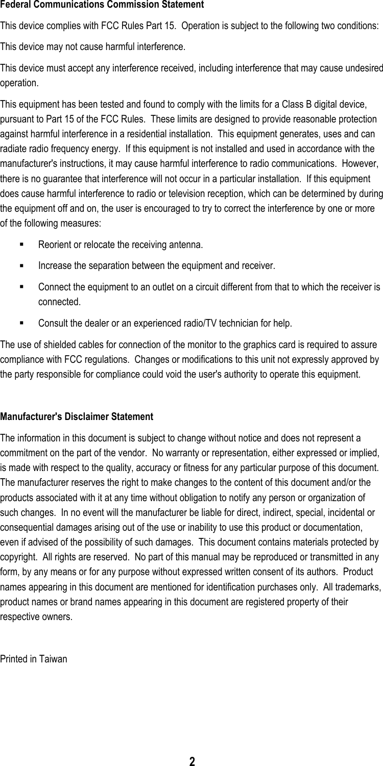
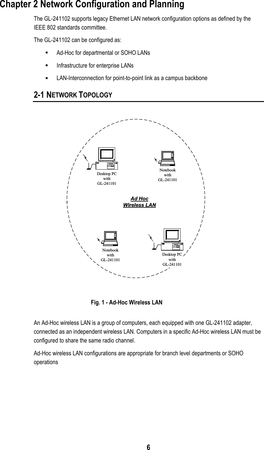

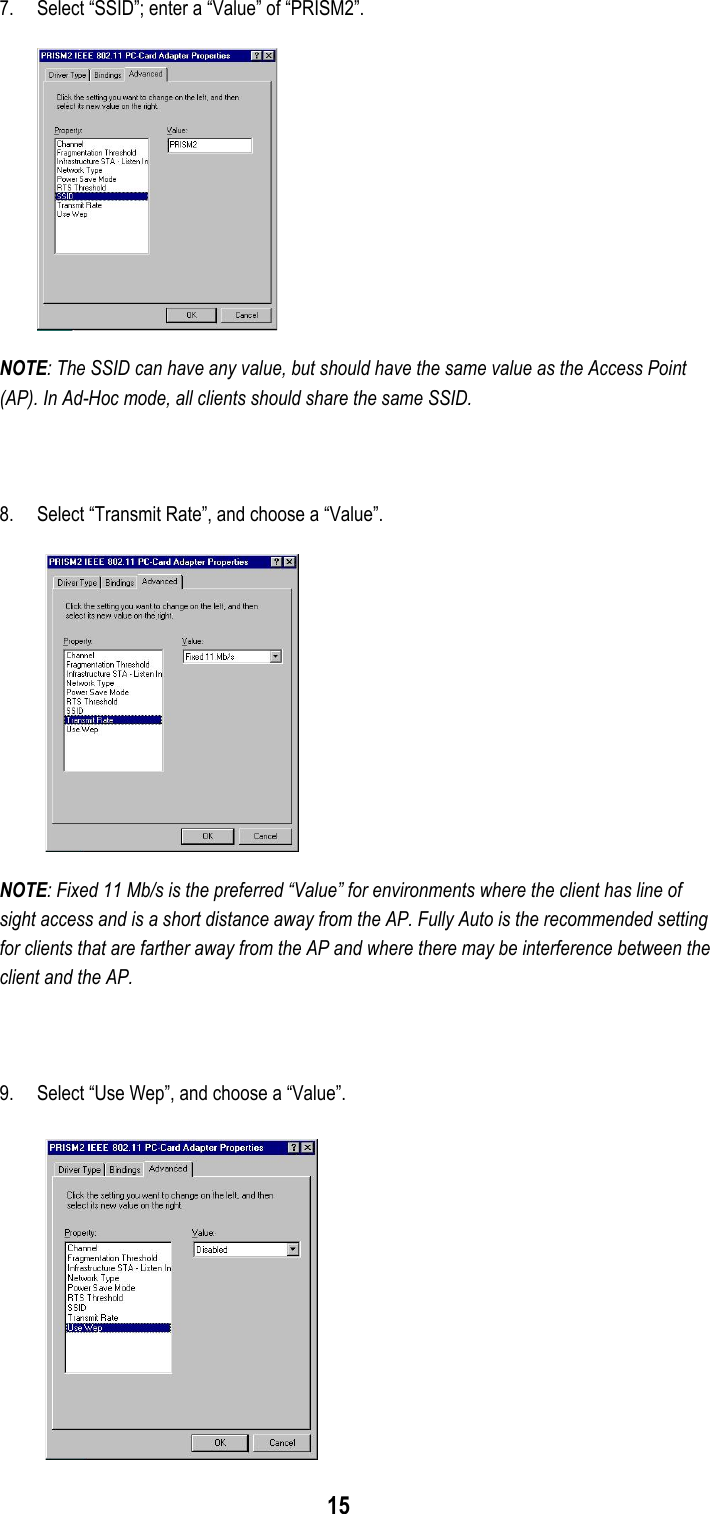
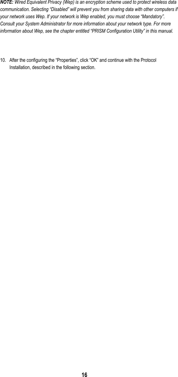
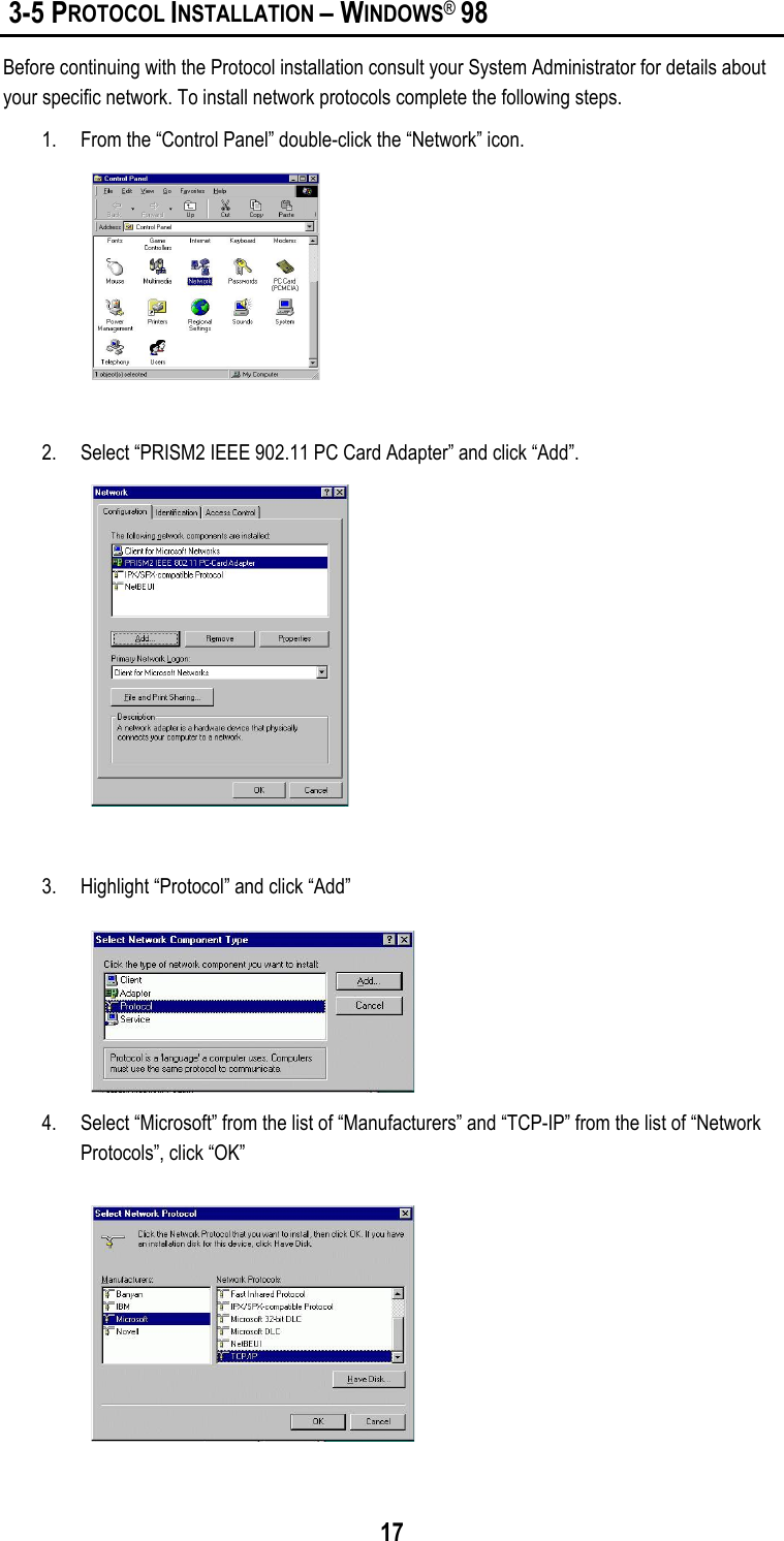
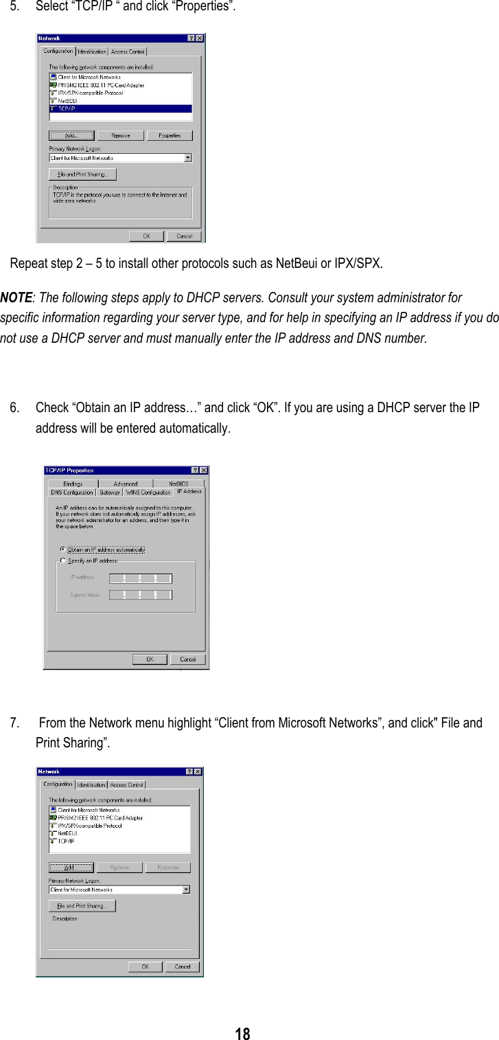
![28 APDTIMINT=3 APCFPOLLABLE=false APCFPOLLREQ=false APCFPPERIOD=3 APCFPMAXDURATION=100 APPROBEDELAY=100 APCHANNEL=6 APBASICRATES="2 4" APOPRATES="2 4 11 22" ; Station Settings (SSID is all we have for now) ; Set the DESIRED_SSID to the SSID of the AP which you want to link. DESIRED_SSID="WLAN_PRISM2" 12) Edit your network.opts file to set up your IP settings. # vi /etc/pcmcia/network.opts ;Transceiver selection, for some cards -- see 'man ifport' IF_PORT="" ; Use BOOTP? [y/n] BOOTP="n" ; Use DHCP? [y/n] ; If your local network has DHCP, you can set DHCP to 'y' then save the ; file and exit.If you set DHCP to 'n', you must set the items below. DHCP="n" ; Host's IP address, netmask, network address, broadcast address ; It is a example to set the items for my local network. You must depend ; on your system. IPADDR="192.168.0.201" NETMASK="255.255.255.0" NETWORK="192.168.0.0" BROADCAST="192.168.0.255" ; Gateway address for static routing GATEWAY="192.168.0.1" ; Things to add to /etc/resolv.conf for this interface DOMAIN="lcat" SEARCH="](https://usermanual.wiki/Global-Sun-Technology/GL2411020700/User-Guide-114208-Page-28.png)