Global Sun Technology GL2411AP Wireless Access Point User Manual users manual
Global Sun Technology Inc Wireless Access Point users manual
UserManual.wiki
>
Global Sun Technology
>
GL2411AP User Manual
users manual
Navigation menu
Upload a User Manual
Namespaces
Wiki Guide
HTML
PDF
Info
Views
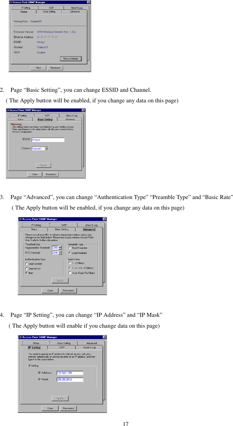
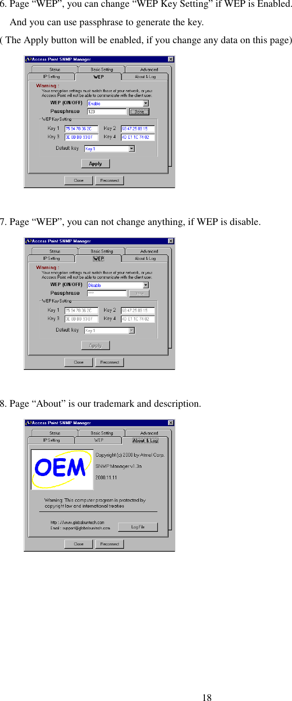
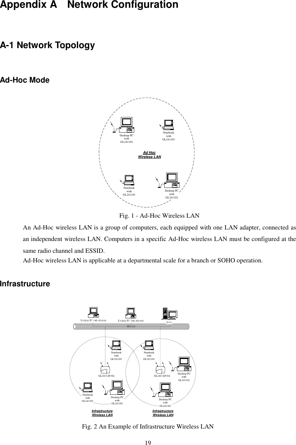
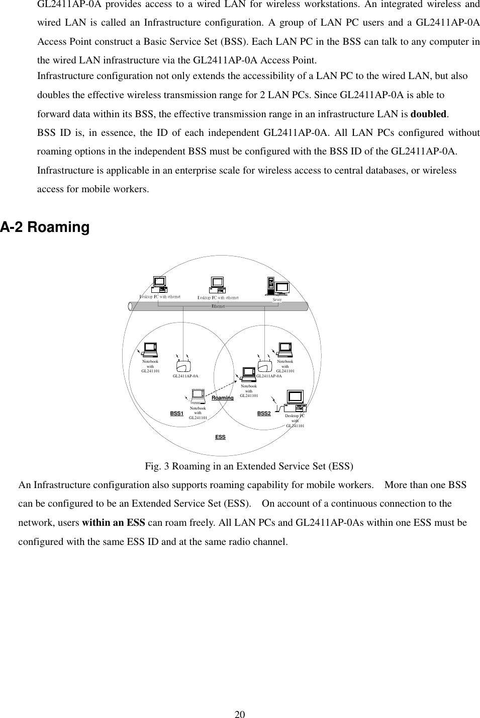
User Manual
Discussion / Help
Navigation