Global Sun Technology GL2411MP-MP 11Mbps WLAN Mini PCI Card User Manual Manual GL2411MP MP
Global Sun Technology Inc 11Mbps WLAN Mini PCI Card Manual GL2411MP MP
Contents
- 1. Manual Part 1
- 2. Manual Part 2
Manual Part 1

11Mbps Wireless Network
PCI Adapter User Manual
version 1.0
Manufacturer's Disclaimer Statement
The information in this document is subject to change without notice and does not represent a
commitment on the part of the vendor. No warranty or representation, either expressed or
implied, is made with respect to the quality, accuracy or fitness for any particular purpose of
this document. The manufacturer reserves the right to make changes to the content of this
document and/or the products associated with it at any time without obligation to notify any
person or organization of such changes. In no event will the manufacturer be liable for direct,
indirect, special, incidental or consequential damages arising out of the use or inability to use
this product or documentation, even if advised of the possibility of such damages. This
document contains materials protected by copyright. All rights are reserved. No part of this
manual may be reproduced or transmitted in any form, by any means or for any purpose
without expressed written consent of its authors. Product names appearing in this document
are mentioned for identification purchases only. All trademarks, product names or brand
names appearing in this document are registered property of their respective owners.
Federal Communication Commission Interference Statement
This equipment has been tested and found to comply with the limits for a Class B
digital device, pursuant to Part 15 of the FCC Rules. These limits are designed to
provide reasonable protection against harmful interference in a residential installation.
This equipment generates, uses and can radiate radio frequency energy and, if not
installed and used in accordance with the instructions, may cause harmful interference
to radio communications. However, there is no guarantee that interference will not
occur in a particular installation. If this equipment does cause harmful interference to
radio or television reception, which can be determined by turning the equipment off
and on, the user is encouraged to try to correct the interference by one of the following
measures:
-Reorient or relocate the receiving antenna.
-Increase the separation between the equipment and receiver.
-Connect the equipment into an outlet on a circuit different from that
to which the receiver is connected.
-Consult the dealer or an experienced radio/TV technician for help.
This device complies with Part 15 of the FCC Rules. Operation is subject to the
following two conditions: (1) This device may not cause harmful interference, and (2)
this device must accept any interference received, including interference that may
cause undesired operation.
FCC Caution: Any changes or modifications not expressly approved by the party
responsible for compliance could void the user's authority to operate this equipment.

IMPORTANT NOTE:
FCC Radiation Exposure Statement:
This equipment complies with FCC radiation exposure limits set forth for an
uncontrolled environment. This equipment should be installed and operated with
minimum distance 20cm between the radiator & your body.
This transmitter must not be co-located or operating in conjunction with any other
antenna or transmitter.
This device is intended only for OEM integrators under the following
conditions:
1) The antenna must be installed such that 20 cm is maintained between the antenna
and users, and
2) The transmitter module may not be co-located with any other transmitter or
antenna.
As long as 2 conditions above are met, further transmitter test will not be required.
However, the OEM integrator is still responsible for testing their end-product for any
additional compliance requirements required with this module installed (for example,
digital device emissions, PC peripheral requirements, etc.).
IMPORTANT NOTE: In the event that these conditions can not be met (for example
certain laptop configurations or co-location with another transmitter), then the FCC
authorization is no longer considered valid and the FCC ID can not be used on the
final product. In these circumstances, the OEM integrator will be responsible for re-
evaluating the end product (including the transmitter) and obtaining a separate FCC
authorization.
End Product Labeling
This transmitter module is authorized only for use in device where the antenna may be
installed such that 20 cm may be maintained between the antenna and users (for
example : Access Point). The final end product must be labeled in a visible area with
the following: “Contains TX FCC ID: O7J-GL2411MP-MP”.
Manual Information That Must be Included
The OEM integrator has to be aware not to provide information to the end user
regarding how to install or remove this RF module in the users manual of the end
product which integrate this module.
The users manual for OEM integrators must include the following information in a
prominent location “ IMPORTANT NOTE: To comply with FCC RF exposure
compliance requirements, the antenna used for this transmitter must be installed to
provide a separation distance of at least 20 cm from all persons and must not be co-
located or operating in conjunction with any other antenna or transmitter.

3
Table of Contents:
TABLE OF CONTENTS: ................................................................................................................ 3
INTRODUCTION............................................................................................................................ 4
PRODUCT FEATURES....................................................................................................................... 4
SYSTEM REQUIREMENTS ................................................................................................................ 4
ONE CD-ROM DRIVEGETTING STARTED.................................................................. 4
GETTING STARTED......................................................................................................... 5
GETTING TO KNOW THE 11MBPS WIRELESS NETWORK PCI ............................................................ 5
WIRELESS NETWORK PCI’S LEDs......................................................................................... 5
SETTING UP THE WIRELESS NETWORK............................................................................................ 5
INSTALLING YOUR 11MBPS WIRELESS NETWORK PCI..................................................................... 7
CONFIGURING YOUR WIRELESS NETWORK PCI............................................................... 12
Link Info. Page ....................................................................................................................... 12
Configuration Page................................................................................................................. 13
Security Page.......................................................................................................................... 15
SiteSurvey Page...................................................................................................................... 16
About Page............................................................................................................................. 18
APPENDIX A: TROUBLESHOOTING........................................................................................ 19
APPENDIX B: NETWORKING BASIS........................................................................................ 24
APPENDIX C: 802.1X AUTHENTICATION SETUP .................................................................. 37
802.1X AUTHENTICATION INFRASTRUCTURE ................................................................................. 38
SUPPLICANT: WIRELESS NETWORK PCI ........................................................................................ 39
AUTHENTICATOR: WIRELESS NETWORK ACCESS POINT ................................................................. 58
RADIUS SERVER: WINDOW2000 SERVER....................................................................................... 60
APPENDIX D: GLOSSARY.......................................................................................................... 82
APPENDIX E: TECHNICAL SPECIFICATION ......................................................................... 87
4
INTRODUCTION
The 11Mbps Wireless Network Adapter delivers
reliable and high-speed wireless performance of
11Mbps
Product Features
- Full 2.4GHz IEEE 802.11b standard and Wi-Fi compliant
- High-Speed data transfer rate of up to 11Mbps with automatic fallback under
noisy environment or longer distance.
- Excellent distance coverage with reliable performance.
- Plug-and-Play setup and operation.
- Supports strong security of 802.1x, which is available in Windows XP, and WEP
128 bit security.
- Supports software upgrade for Wi-Fi Access Protected (WPA) security available
in Q3 ‘03.
- Supports Ad-Hoc, Infrastructure and wireless roaming.
- Easy-to-use software client management utility for configuration.
System Requirements
Ø Windows 98, 98SE, Millennium Edition (ME), 2000 and XP computers
Ø PC with Pentium III 600MHz system or above is recommended
Ø Equipped with at least one PCIbus socket or PCIbus adapter.
Ø One CD-ROM drive
5
GETTING STARTED
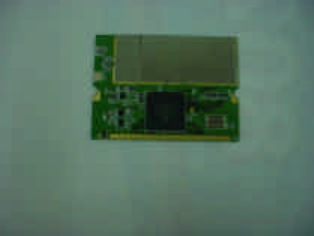
Getting To Know The 11Mbps Wireless Network PCI
WIRELESS NETWORK PCI’S LEDs
Ø Power LED
ON when the unit is powered up
Ø WLAN LED
ON indicates WLAN connection; blink indicates wireless activity
Setting Up The Wireless Network
There two wireless network topologies that you can setup your wireless card with.
One is called “Ad-Hoc”, and the other is “Infrastructure”. On an Ad-Hoc network,
two or more computers each has at least one wireless network client device such as
wireless PCI installed, establish point-to-point data communication with each other.
While on an Infrastructure network, every wireless station communicates through
Access Points.
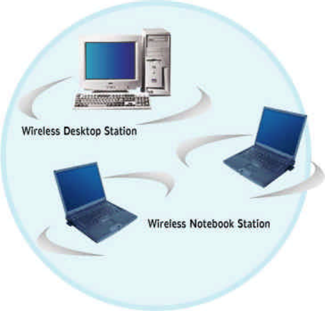
Setting Up Ad-Hoc Network
The idea of Ad-Hoc Network is rather simple. All the wireless station are set to use
the same BSS ID and channel to establish communication linkage with each other to
form a point-to-point network for data transmission and reception.
6
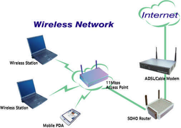
Setting Up Infrastructure Network
In order to setup an Infrastructure of a wireless network such as the example shown
above, you will need the following:
1. A broadband Internet connection.
2. ADSL or Cable modem provided by your ISP as part of the broadband connection
installation.
3. A Router that connects to the ADSL/Cable modem for internet connection sharing.
4. An Access Point to connect with the Router to form a wireless infrastructure
network.
5. Wireless clients equipped with wireless networking devices such as wireless PCI
for wireless connection.
In this case, all the wireless clients and Access Point operate under the same channel
with the same ESSID. The wireless clients are all connected to the Access Point for
data transmission.
7
Installing Your 11Mbps Wireless Network PCI
Installing Utility Program
Please note that the installation screens in this quick guide are captured from WindowsXP. The
other Windows systems will have similar screen for the installation procedure.
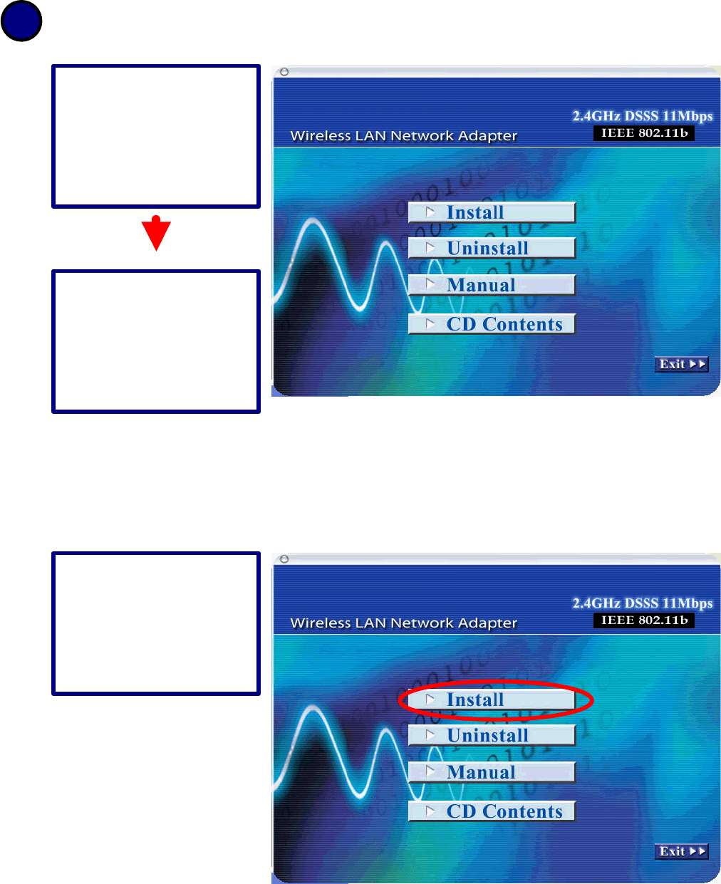
1
Make sure that the
11Mbps Wireless
Network PCI is
NOT
inserted into the Cardbus
slot.
Turn on the computer.
Insert the software CD
into the CD-ROM Drive.
Click on “Install” button
to start Utility
installation.
8
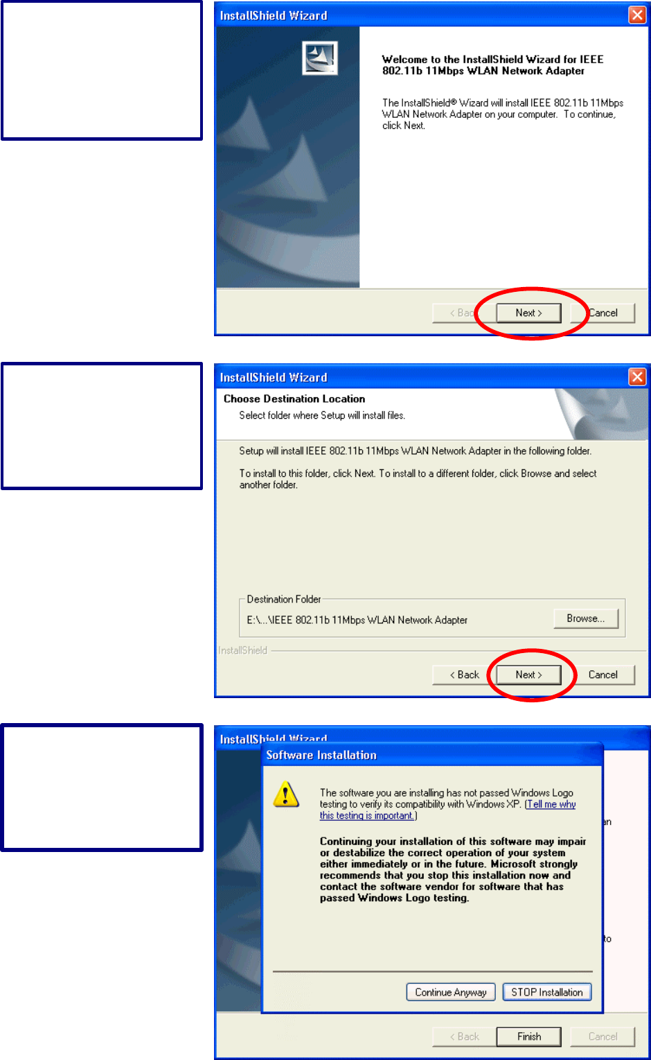
InstallShield Wizard
starts. Click “Next” to
continue.
Click “Next” to install the
program files in the
default folder.
Installation of driver files,
click “Continue
Anyway” to continue.
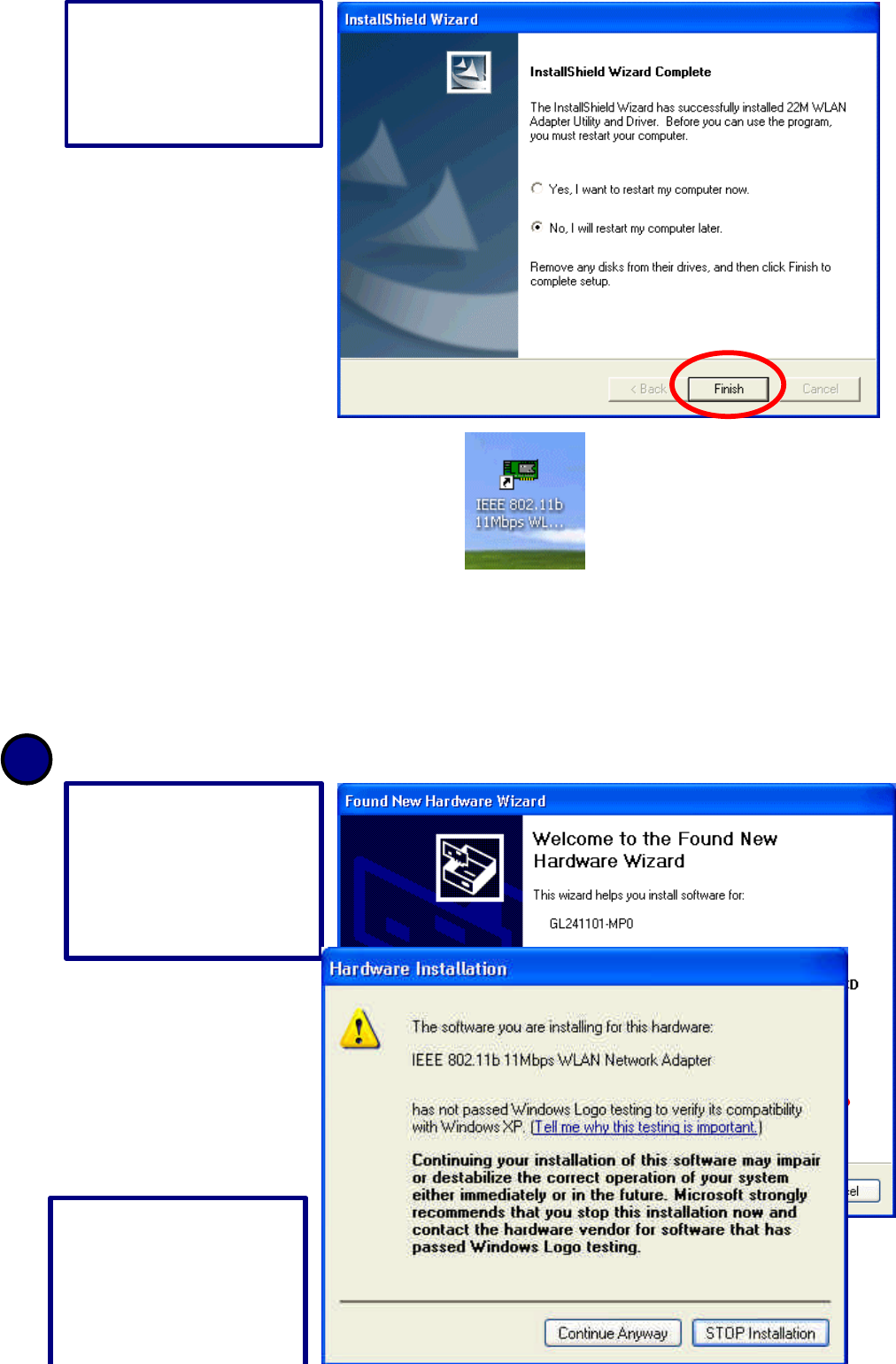
9
The Utility Icon appears in your desktop.
- Turn off your computer
- Insert the 11Mbps Wireless Network PCI into the CardBus slot in your notebook
- Turn on your computer
- Continue with Driver Installation.
Starts Up PCI for the First Time
Select the second option,
and click “Finish” to
complete the installation.
2
Select the second option
and click “Next” to
continue.
click “Continue
Anyway” to proceed.
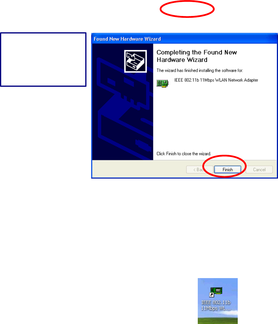
10
Simply, double-click the icon to launch the utility.
Click “Finish” to
complete new hardware
installation.
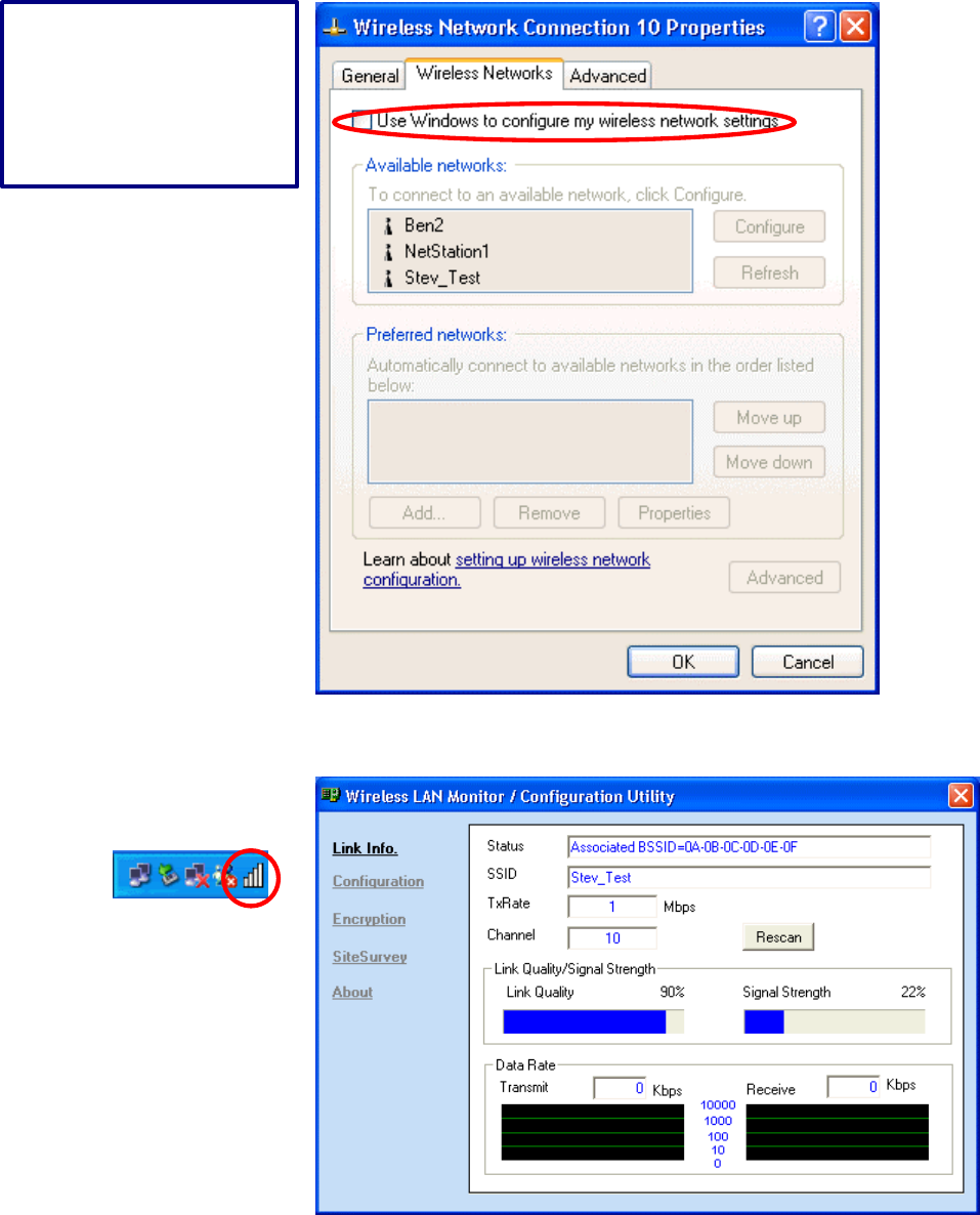
11
Double-click on the utility
icon in the system tray
again to launch the 11Mbps
PCI Utility.
Click off the “Use
Windows to …” option
to
use the 11Mbps PCI
utility.
12
CONFIGURING YOUR WIRELESS NETWORK PCI
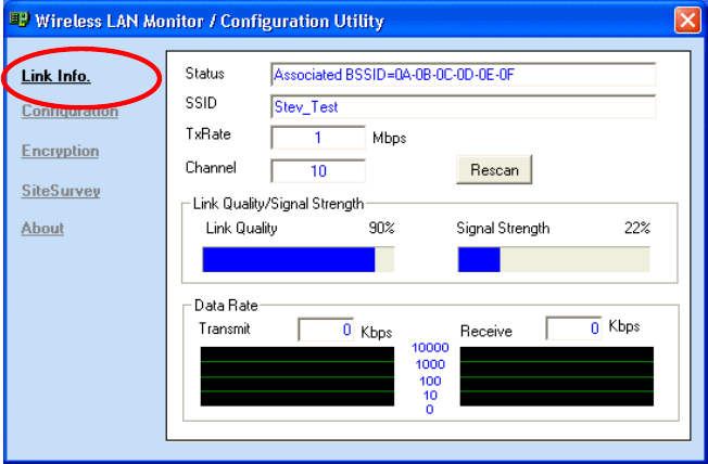
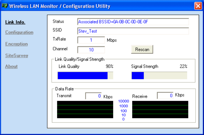
Link Info. Page
This is the default page when the utility starts up.
Status: Shows the BSSID associated, which can be used to identify the wireless
network.
SSID: Shows current SSID, which must be the same for the wireless client and AP in
order for communication to be established.
TxRate: Shows the current data rate used for transmitting.
Channel: Shows the current channel for communication.
Radio Off button: When clicked, you disable the radio signal, and cut-off the wireless
connection.
Link Quality: Shows the link quality of the 11Mbps wireless PCI with the Access
Point when operating under Infrastructure mode.
Signal Strength: Shows the wireless signal strength of the connection between the
11mpbs wireless PCI with the Access Point.
Data Rate: Shows the statistics of data transfer, and the calculation is based on the
number of packets transmitted and received.
13
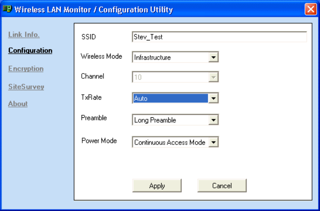
Configuration Page
This is the page where you can change the basic settings of the Access Point with the
minimum amount of effort to adjust a secure wireless network.
SSID: Service Set Identifier, which is a unique name shared among all clients and
nodes in a wireless network. The SSID must be identical for each clients and nodes in
the wireless network.
BSS Type: There are two types available for selection
l Infrastructure – to establish wireless communication with LAN and other
wireless clients through the use the Access Points.
l Ad-Hoc – to establish point-to-point wireless communication directly with
other wireless client devices such as wireless network PCI.
Channel: The value of channel that AP will operate in. You can select the channel
range of 1 to 11 for North America (FCC) domain, 1 to 13 for European (ETSI)
domain and 1 to 14 for Japanese domain.
Tx Rate: Select the data rate for data transmission.
Preamble: Select Long or Short Preamble type. Preamble is a sequence of bits
transmitted at 1Mbps that allows the PHY circuitry to reach steady-state demodulation
and synchronization of bit clock and frame start. Two different preambles and headers
are defined: the mandatory supported Long Preamble and header, which interoperates
with the 1 Mbit/s and 2 Mbit/s DSSS specification (as described in IEEE Std 802.11),
and an optional Short Preamble and header (as described in IEEE Std 802.11b). At the
14
receiver, the Preamble and header are processed to aid in demodulation and delivery
of the PSDU. The Short Preamble and header may be used to minimize overhead and,
thus, maximize the network data throughput. However, the Short Preamble is
supported only from the IEEE 802.11b (High-Rate) standard and not from the original
IEEE 802.11. That means that stations using Short-Preamble cannot communicate
with stations implementing the original version of the protocol.
Power Mode: There are 3 modes to choose from
l Continuous Access Mode (default) – the PCI is constantly operating with
full power and it consumes the most power
l Maximum Power Save – the PCI consumes the least power and only
operates when there is wireless network activity.
l Power Save – the PCI consumes the moderate level of power.
For the changes made to any of the items above to be effective, click “Apply”. The
screen will be changed back to Link Info. Page
15
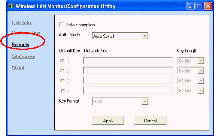
Security Page
This is the page where you configure Security settings of your 11Mbps wireless PCI.
Data Encryption: Click the box to enable Data Encryption feature.
Aut. Mode: There are three modes available to choose from.
l Open Authentication – the sender and receiver do not share secret Key for
communication. Instead, each party generates its own key-pairs and ask the
other party to accept it. The key is regenerated when the connection is
established every time.
l Shared Authentication – the sender and receiver shares the common key
for data communication, and the key is used for extended length of time.
l Auto – depend on the communication to establish, and automatically use
the proper authentication mode.
The following will only be activated to allow for configuration when Data
Encryption is enabled.
Default Key: select one of the 4 keys to use.
Network Key: enter values to these fields, either in HEX or ASCII formats. You only
have to enter the key that you will use
Key Length: select 64 or 128 bits as the length of the keys
Key Format: ASCII or HEX (Please refer to Appendix G: Glossary for details about
these two formats).
16
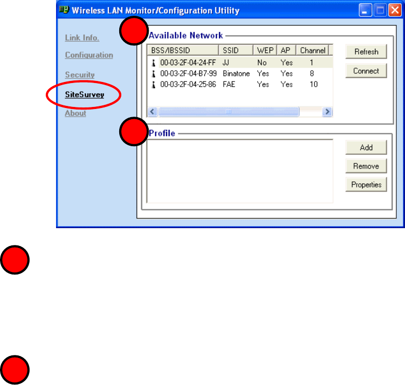
SiteSurvey Page
This page allows to utilize the SiteSurvey function to scan for the available wireless
network (wireless clients and Access Points) and select one to establish wireless
communication.
Available Network – displays the wireless networks (wireless clients and Access
Points) that are in your signal range. Select any one of them and establish
communication by simply mouse double-click or a single click on the
“Connect” button.
Click “Refresh” button to start scanning for available network again.
Profile – You can create and manage the created profiles for Home, offices or
public areas.
By double-clicking on one of the created profile, the setting will adapt to the
configuration such as SSID, channel, and WEP settings saved by that particular
profile.
Click to select any one of the profiles, and you can
Click on “Remove” button to remove the profile, or
Click on “Properties” button to view and change its settings. The Properties is
very similar to that of adding profile.
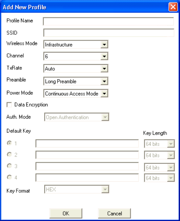
Click “Add” to add a profile, and the following screen would appear.
1
1
2
2
17
All the detail information about each settings and configuration item are described in
previous Configuration and Security Page sessions. Please refer to those two sessions
for more information.
When you finish enter the setting for this profile, click “OK” to add a new profile.
18
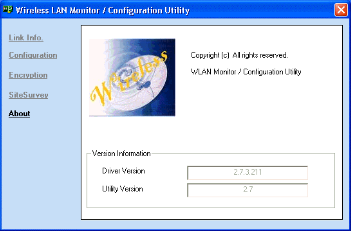
About Page
This page displays some information about the 11mpbs PCI utility, which includes the
version numbers for Driver, Firmware and Utility.
When there is new version of software available for upgrade, you will be able to
identify by version numbers.
19
APPENDIX A: TROUBLESHOOTING
This chapter provides solutions to frequently encountered problems that can occur
during the installation and operation of the 11Mbps Wireless Network PCI. Please
read through the following to solve your problems.
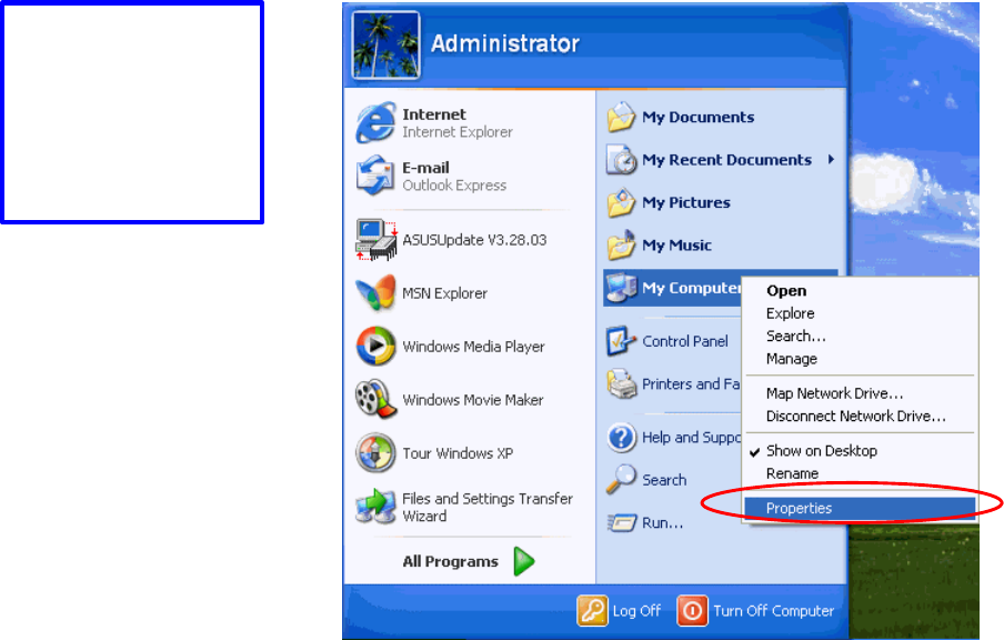
1. The wireless clients cannot access the network in the infrastructure mode.
Ø Check that the wireless network device is being installed and working
properly.
Go to “Start” >
Right mouse click
on “My Computer”
> “Properties”
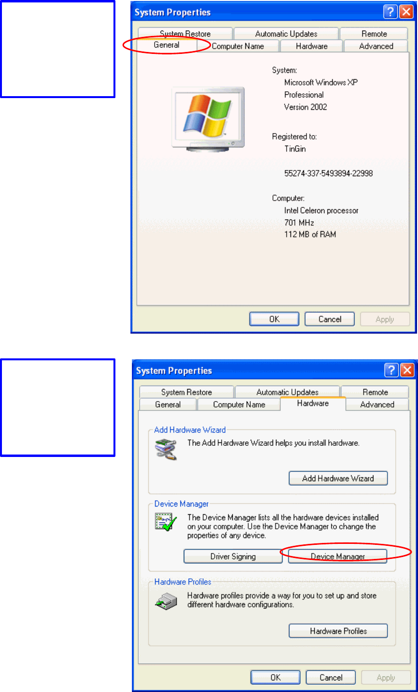
20
Go to “Device
Manager”
Go to “Hardware”
21
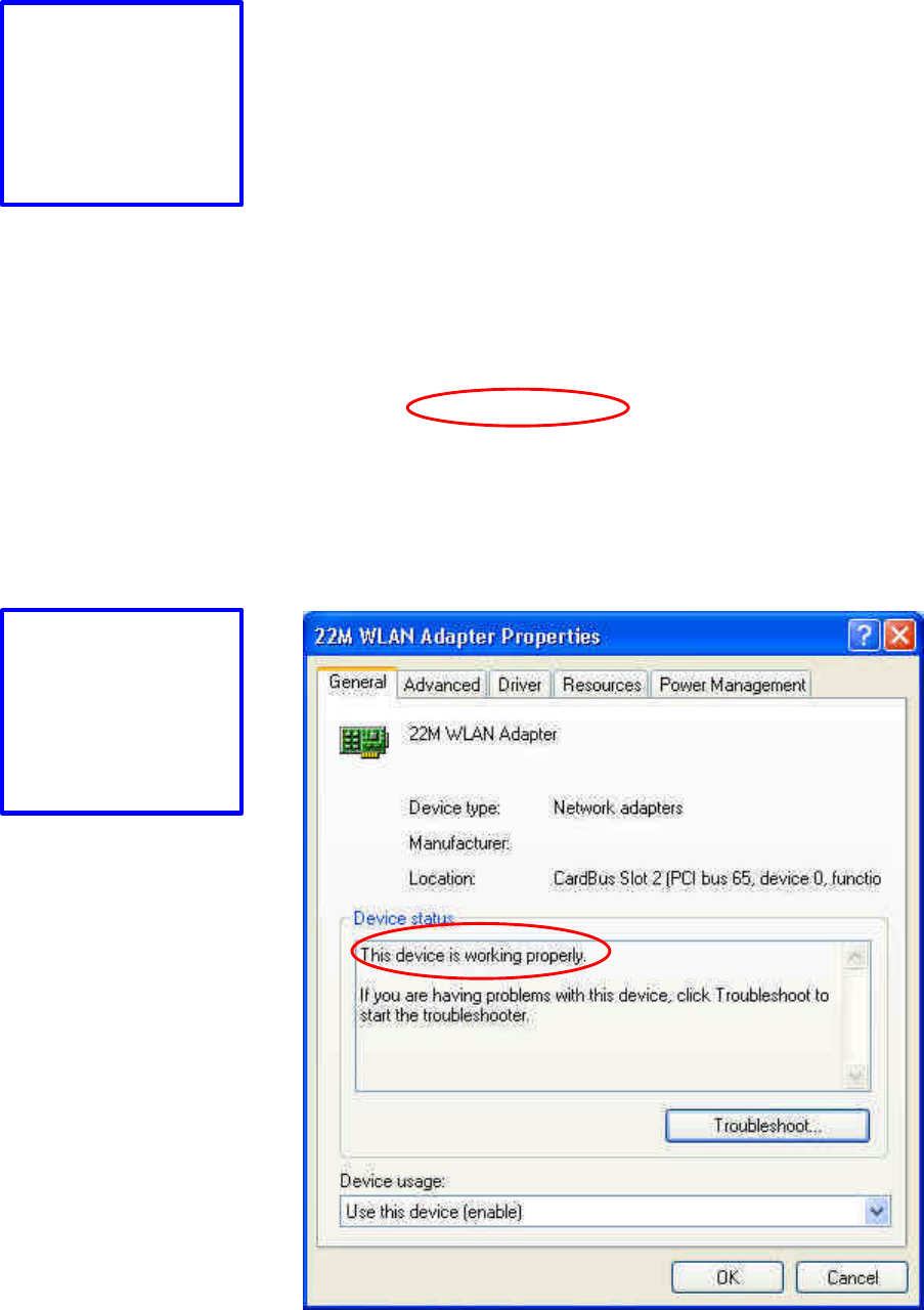
Right mouse click
on the wireless
network adapter.
Go to “Properties”
Check and make
sure that the
network adapter is
working properly
22
2. What is the difference between 11Mbps and 11Mbps wireless products?
What’s the benefit of 11Mbps Wireless Access Point?
The 11Mbps is made possible by the new modulation method called PBCC
developed by TI, which is different from the current CCK modulation method
for 11Mbps. The 11Mbps Wireless Access Point offers double data rate than that
of 11Mbps with 20% more distance coverage. The 11Mbps wireless products
also operate in the 2.4GHz ISM band and they are backward compatible with
11Mbps wireless products.
3. What is Roaming?
Roaming is the ability of portable computers, e.g., Packet PC and notebook, to
have consistent and continuous data transmission/reception throughout an area
covered by more than one Wireless Access Point. In order to achieve seamless
connectivity, all the wireless clients and Access Points must be set to use the
same SSID. When a user walked out of the coverage area of one AP into
another, the wireless client network device will automatically reestablish
connection with the new AP.
4. What is a MAC Address?
The Media Access Control (MAC) address is a unique number assigned by the
manufacturer to any Ethernet networking devices, e.g. a network adapter, that
allows the network to identify it at the hardware level. Unlike IP addresses,
which can be changed or dynamically assigned by the network, the MAC
address of a networking device is permanent.
5. What is WEP?
Wired Equivalent Privacy (WEP) is a type of data encryption mechanism
described in the IEEE 802.11 standard. The 11Mbps Wireless Access Point
supports 64/128/256 bit shared key for WEP.
6. Would the information be transmitted securely in the air?
WLAN offers two layers of protection for security. First layer is on the hardware
level. As with Direct Sequence Spread Spectrum (DSSS) technology, it has the
inherent security feature of scrambling. Second of all, on the software level, the
security control is made possible by Wired Equivalent Privacy (WEP) for access
control.
7. What is ISM band?
23
The FCC and their counterparts outside of the U.S. have set aside bandwidth for
unlicensed use in the ISM (Industrial, Scientific and Medical) band. The 2.4GHz
unlicensed ISM band is available worldwide, which presents the opportunity for
the global market of 802.11b high speed wireless products.
8. What is 4X mode?
This is a proprietary wireless data transmission mode provided by TI, which
enhances TI’s 11Mbps PBCC speed to reach data throughput to over 12Mbps.
Since it is not IEEE 802.11b standard wireless data mode, in order to allow 4X
mode, both the receiving and transmitting parties must be using TI solution.
24
APPENDIX B: NETWORKING BASIS
This chapter will help you learn the basics of home networking.
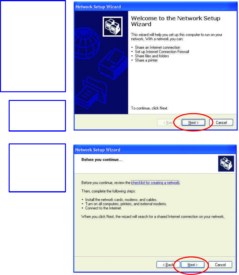
Using the Windows XP Network Setup Wizard
Go to Start menu >
Control Panel >
Network Connections
In the menu on the left
side of the window,
select “Set up a home
or small office
network”
Click “Next” to
procced
Click “Next” to
continue
25
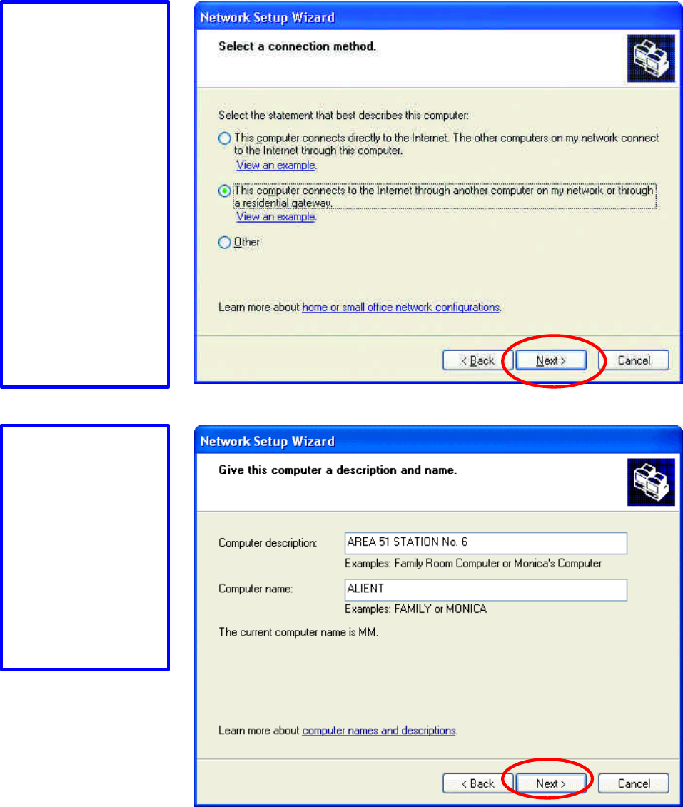
Select the option
that best describes
how you connect
your computer to the
Internet.
In the case of using
router in the
network, choose the
second option.
Click “Next” to
continue.
1. Enter a short
description for your
computer.
2. Enter a name for
your computer
to be
recognized among
the network.
3. Click “Next” to
continue.
26
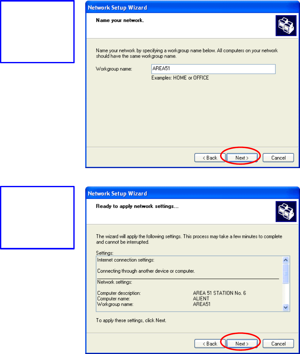
Enter “Workgroup
name” for your
home network.
Click “Next” to
continue”
Click “Next” and
wait for the wizard
to apply the settings.
27
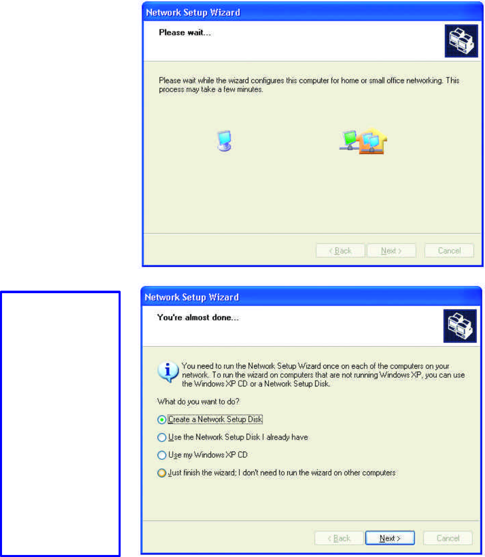
You may create a
network setup disk
which saves you the
trouble of having to
configure every PCs
in your network.
Select the first
choice, and insert a
floppy disk into
your disk drive
Click “Next” to
continue.
28
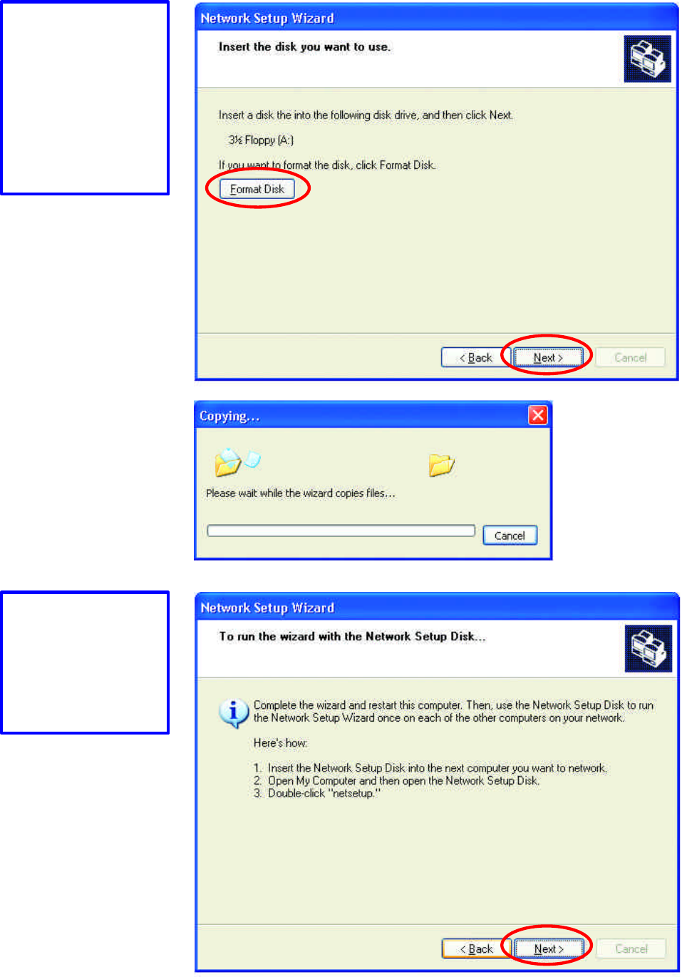
Click “Format
Disk” if you wish to
format the disk.
Click “Next” to
copy the necessary
files to the disk.
Click “Next” to
continue with the
Network Setup
Wizard
29
!Note: Now you may use the Network Setup Disk you just created in any PCs in your
network that you wish to setup. Simply insert the Network Setup Disk into the disk
drive of a PC, and open to browse the content of the disk with “My Computer” or
“Windows File Manager”. Double-click and run the file “netsetup” for the program
to handle the rest.
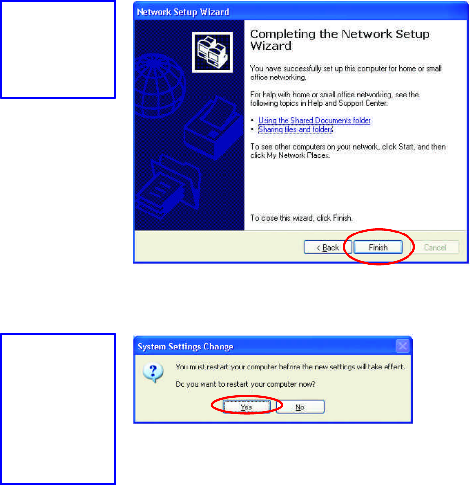
Click “Finish” to
complete the
Network Setup
Wizard.
System will now
have to restart in
order for the new
settings to be
effective.
Click “Yes” to
restart the computer
30
Checking IP Address of Your Computer in Windows XP
Sometimes you will need to know the IP address of the computer that you are using.
For example, when you want to make sure that your computer is in the same network
domain as that of your Access Point for you can configure and access the AP.
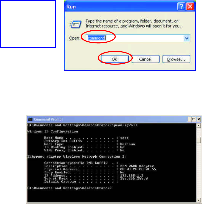
When the command prompt window appears, type command “ipconfig /all” and press
Enter. This command will display the IP addresses of all the network adapters in
your computer.
In this case, the IP address of your network adapter is 192.168.1.2, which means your
Access Point must have an IP address of 192.168.1.xxx in order for you to be able to
access it.
If the IP address is assigned by DHCP server on the network, there are chances you
might have to release the IP and acquire it from DHCP server again. Here is how
you do it.
Go to Start menu >
Run > type
“command”
Click “OK”
31
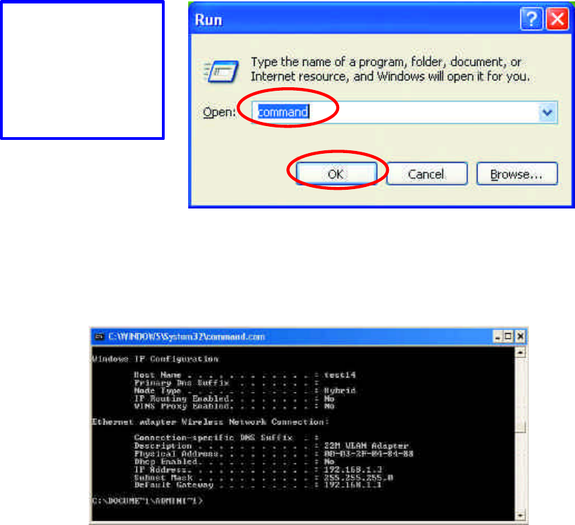
Type command, “ipconfig /renew” in the command prompt window and press Enter.
This command releases the current IP address and acquire it from the network, i.e.
DHCP server, once more.
In this case, the IP address that we acquired is 192.168.1.3. However, it’s often that
the acquired IP address of the network adapter might would not be the same.
!Note: To renew IP under Windows 98 and Windows ME, you will have to go to the
Start menu > Run > type winipcfg and click “OK”. The Windows IP Configuration
Menu window would appear, where you first click “release” button to release the
current IP address, followed by clicking of “Renew” to acquire a new IP address from
network.
If the above methods for IP renew fail, you will have to try and restart the computer,
which will reinitializes the network adapter settings during startup including renewing
IP address. If you still have problems getting an IP address after computer restarts,
you will have to consult with your MIS in your office or call computer and network
technicians.
Go to Start menu >
Run > type
“command”
Click “OK”
32
Dynamic IP Address V.S. Static IP Address
By definition Dynamic IP addresses are the IP addresses that are being automatically
assigned to a network device on the network. These Dynamically assigned IP
addresses will expire and may be changed over time.
Static IP addresses are the IP addresses that users manually enter for each of the
network adapters.
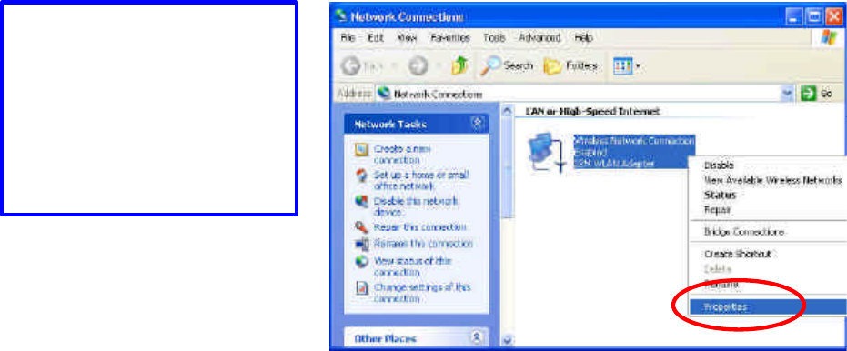
!Note: There might be two or more Local Area Connection to choose from. You must
select the one that you will use to connect to the network.
Go to Start menu > Control
Panel > Network
Connections > Right-
click on
the active Local Area
connection > Select
“Properties”
33
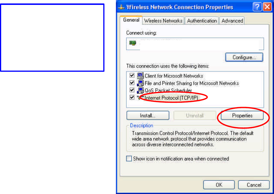
The Local Area Connection
Properties would appear.
Select “Internet Protocol
(TCP/IP)” and Click
“Properties” to continue.
IEEE 802.11b 11Mbps WLAN Network Adapter
34
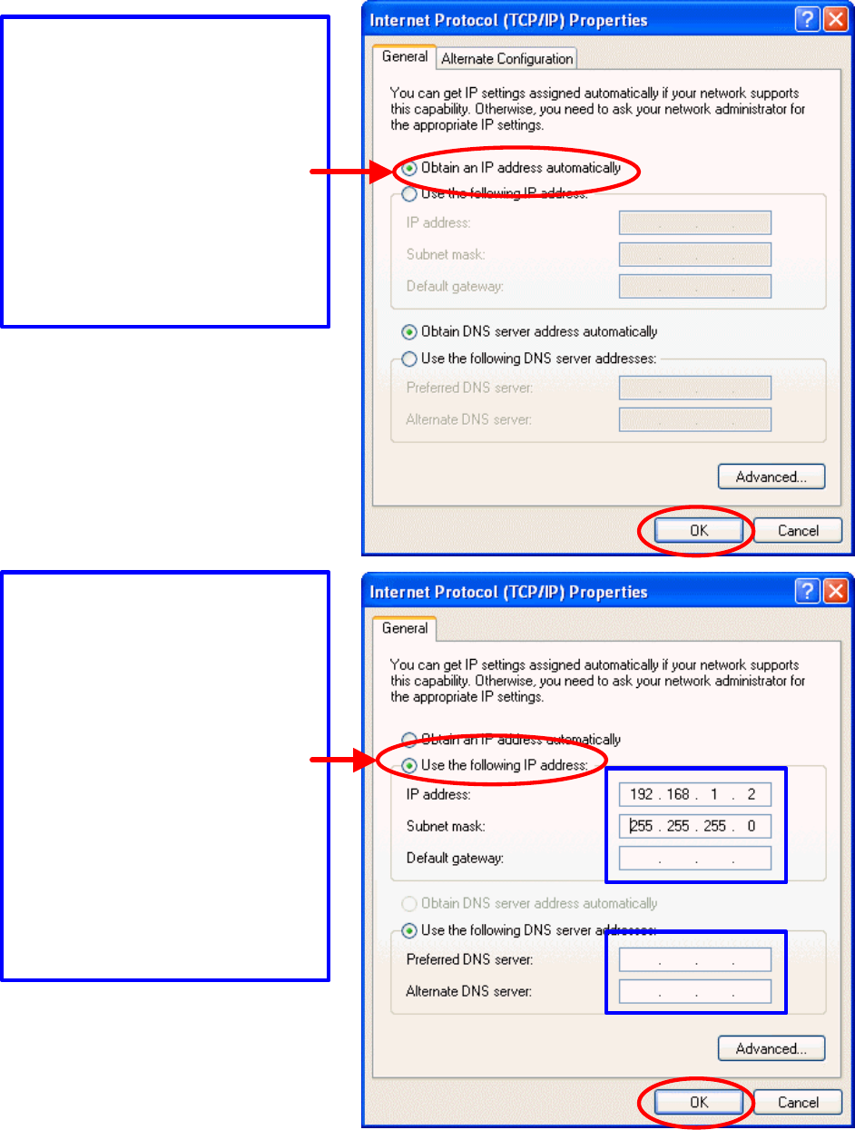
Dynamically Assigned IP Address
Static IP Address
The TCP/IP Properties window
appears.
Select “Obtain an IP address
automatically” if you are on a
DHCP enabled network.
Click “OK” to close the window
with the changes made
Select “Use the following IP
address”
Enter the IP address and subnet
mask fields.
Enter the IP address of the Router
in the Default gateway field.
Enter the IP address of the Router
in the DNS server field
Click “Ok” to close the window
35
!Note: The IP address must be within the same range as the wireless route or Access
Point.
Wireless Network in Windows 2000
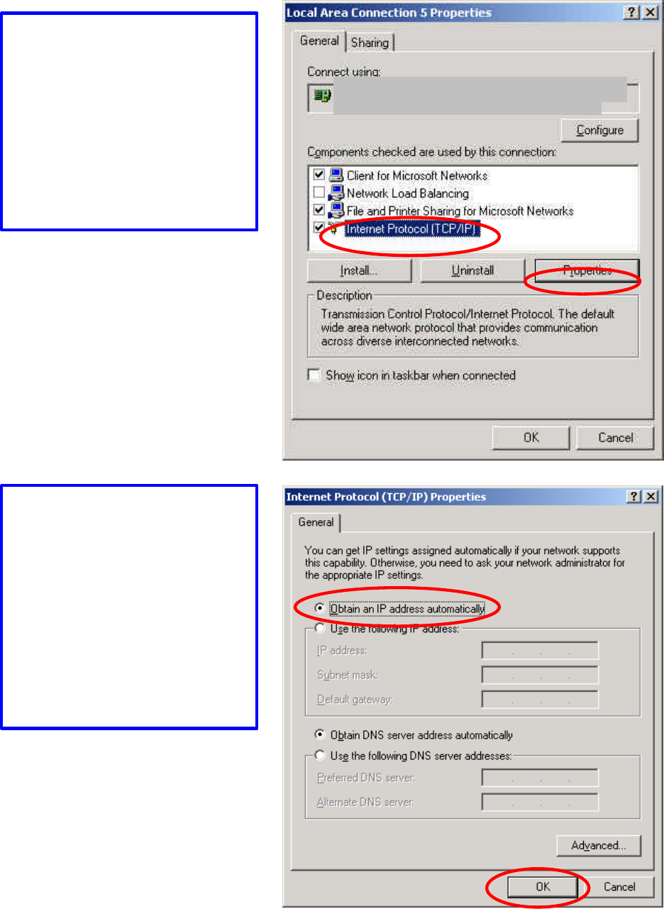
The TCP/IP Properties window
appears.
Select “Obtain an IP address
automatically” if you are on a
DHCP enabled network.
Click “OK” to close the window
with the changes made
Go to Start menu > Settings >
Network and Dial-up
Connections > Double-click on
the Local Area Connection
Select “Internet Protocol
(TCP/IP)” and click
“Properties”
IEEE 802.11b 11Mbps WLAN Network Adapter
36
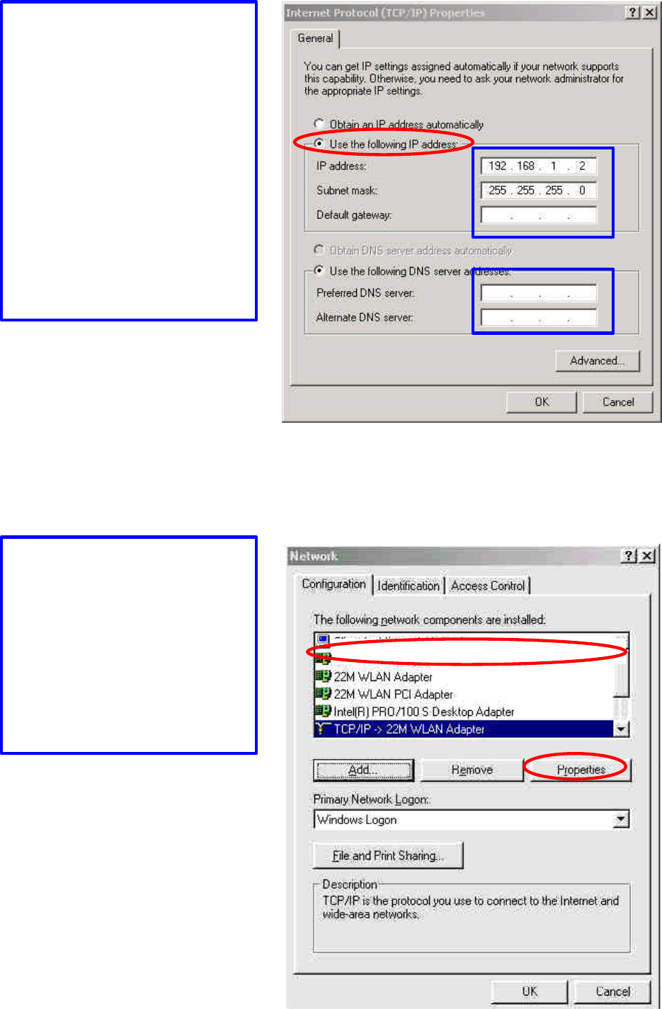
Wireless Network In Windows 98 and Windows ME
Select “Use the following IP
address”
Enter the IP address and subnet
mask fields.
Enter the IP address of the Router
in the Default gateway field.
Enter the IP address of the Router
in the DNS server field
Click “Ok” to close the window
Go to Start menu > Settings >
Control Panel > Double-click on
Network
Select TCP/IP of the network
device
Click “Properties” to continue
IEEE 802.11b 11Mbps WLAN Network Adapter
37
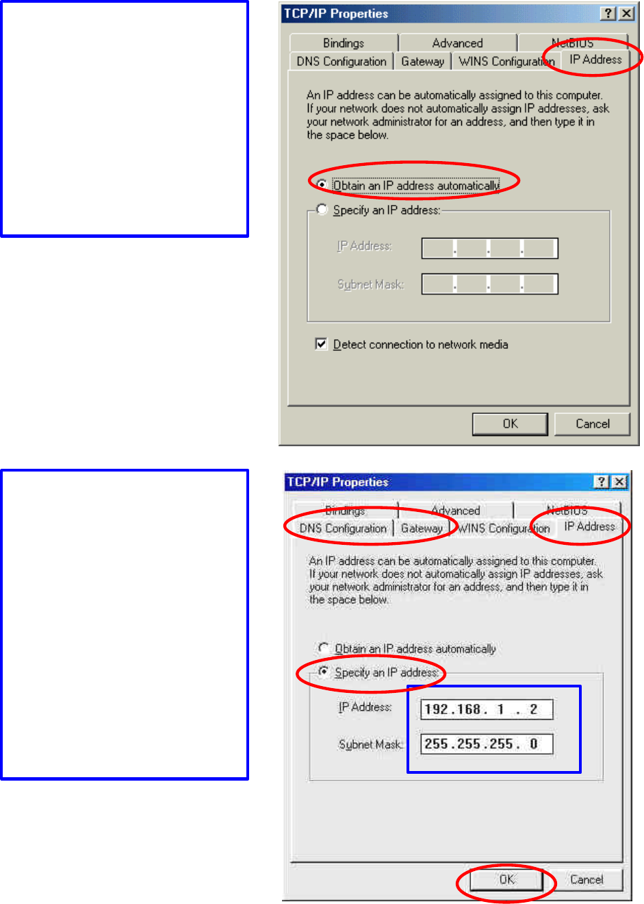
The TCP/IP Properties window
appears.
Select “Obtain an IP address
automatically” if you are on a
DHCP enabled network.
Click “OK” to close the window
with the changes made
Select “Specify an IP address”
Enter the IP address and subnet
mask fields.
In the DNS Configuration Tab
Page, (1) enter the IP address of
the Router in the Default
gateway field.
(2) Enter the IP address of the
Router in the DNS server field
38
APPENDIX C: 802.1x Authentication Setup
There are three essential components to the 802.1x infrastructure: (1) Supplicant, (2)
Authenticator and (3) Server. The 802.1x security supports both MD5 and TLS
Extensive Authentication Protocol (EAP). The 802.1x Authentication is a
complement to the current WEP encryption used in wireless network. The current
security weakness of WEP encryption is that there is no key management and no
limitation for the duration of key lifetime. 802.1x Authentication offers key
management, which includes key per user and key per session, and limits the lifetime
of the keys to certain duration. Thus, key decryption by unauthorized attacker
becomes extremely difficult, and the wireless network is safely secured. We will
introduce the 802.1x Authentication infrastructure as a whole and going into details of
the setup for each essential component in 802.1x authentication.
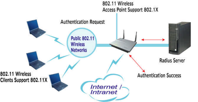
802.1x Authentication Infrastructure
The Infrastructure diagram showing above illustrates that a group of 802.11 wireless
clients is trying to form a 802.11 wireless network with the Access Point in order to
have access to the Internet/Intranet. In 802.1x authentication infrastructure, each of
these wireless clients would have to be authenticated by the Radius server, which
would grant the authorized client and notified the Access Point to open up a
39
communication port to be used for the granted client. There are 2 Extensive
Authentication Protocol (EAP) methods supported: (1) MD5 and (2) TLS.
MD5 authentication is simply a validation of existing user account and password that
is stored in the server with what are keyed in by the user. Therefore, wireless client
user will be prompted for account/password validation every time when he/she is
trying to get connected. TLS authentication is a more complicated authentication,
which involves using certificate that is issued by the Radius server, for authentication.
TLS authentication is a more secure authentication, since not only the Radius server
authenticates the wireless client, but also the client can validate the Radius server by
the certificate that it issues. The authentication request from wireless clients and reply
by the Radius Server and Access Point process can be briefed as follows:
1. The client sends an EAP start message to the Access Point
2. The Access Point replies with an EAP Request ID message
3. The client sends its Network Access Identifier (NAI) – its user name – to the
Access Point in an EAP Respond message.
4. The Access Point forwards the NAI to the RADIUS server with a RADIUS
Access Request message.
5. The RADIUS server responds to the client with its digital certificate.
6. The client validates the digital certificate, and replies its own digital
certificate to the RADIUS server.
7. The RADIUS server validates client’s digital certificate.
8. The client and RADIUS server derive encryption keys.
9. The RADIUS server sends the access point a RADIUS ACCEPT message,
including the client’s WEP key.
10. The Access Point sends the client an EAP Success message along with the
broadcast key and key length, all encrypted with the client’s WEP key.
Supplicant: Wireless Network PCI
Here is the setup for the Wireless Network PCI under Windows XP, which is the only
Operating System that our driver supports for 802.1x. Microsoft is planning on
supporting 802.1x security in all common Windows Operating System including
Win98SE/ME/2000 by releasing Service Pack in 2003.
Please note that the setup illustration is based on our 11Mbps wireless PCI.
40
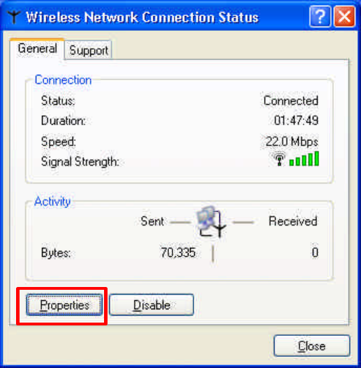
1. Go to Start > Control Panel
2. double-click on “Network Connections”
3. right-click on the Wireless Network Connection that you use with our 11Mbps
wireless PCI.
4. Click “Properties” to open up the Properties setting window.
41
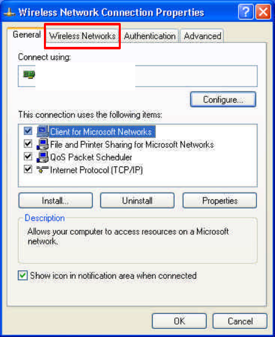
5. Click on the “Wireless Network” tab.
11M WLAN Adapter
42
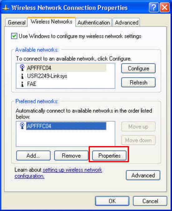
6. Click “Properties” of the available wireless network, which you wish to
connect or configure.
Please note that if you are going to change to a different 802.1x authentication
EAP method, i.e. switch from using MD5 to TLS, , you must remove the current
existing wireless network from your Preferred networks first, and add it in
again.
To configure for using TLS authentication method, please follow steps 7 ~ 25.
Please follow steps 26 ~ for using MD5 authentication method.
43
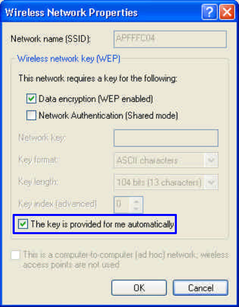
TLS Authentication
7. Select “The key is provided for me automatically” option
8. Click “OK” to close the Wireless Network Properties window.
44
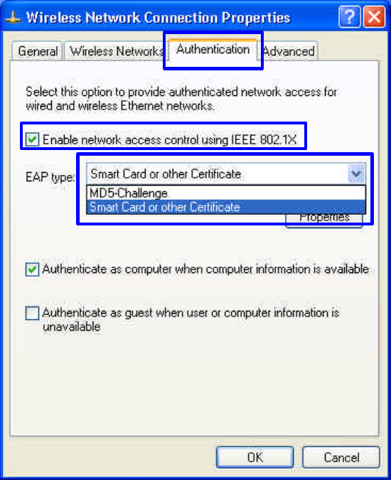
9. Click “Authentication” tab
10. Select “Enable network access control using IEEE 802.1x” option to enable
802.1x authentication.
11. Select “Smart Card or other Certificate” from the drop-down list box for
EAP type.
12. Click “OK” to close the Wireless Network Connection Properties window,
thus make the changes effective.
The wireless client configuration in the zero-configuration utility provided in
Windows XP is now completed for TLS configuration. Before you can enable IEEE
802.1x authentication and have wireless client authenticated by the Radius server, you
have to download the certificate to your local computer first.
45
TLS Authentication – Download Digital Certificate from Server
In most corporations, it requires internal IT or MIS staff’s help to have the
certificated downloaded to your local computer. One of the main reasons is that
each corporation uses its own server systems, and you will need the assistance
from your IT or MIS for account/password, CA server location and etc. The
following illustration is based on obtaining a certificate from Windows 2000
Server which can act as a CA server, assuming you have a valid account/password
to access the server.
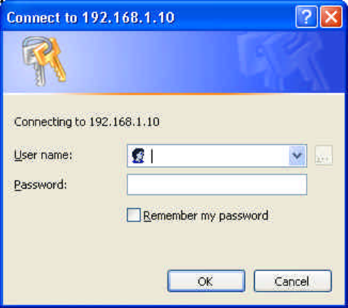
13. Connect to the server and ask for access, and the server will prompt you to
enter your user name and password.
14. Enter your user name and password, then click “OK” to continue.
Please note that we use IP addresses for connection with the server for our
illustration, and the IP of the server is 192.168.1.10.
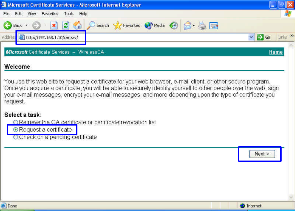
15. After successful login, open up your Internet Browser, and type the following
in the address field.
http://192.168.1.10/certsrv
This is how we connect to the Certificate Service installed in Windows 2000
server.
46
16. Now we are connected to the Certificate Service. Select “Request a
certificate”, and click “Next” to continue.
47
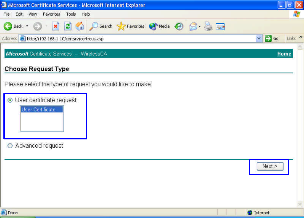
17. Select “User Certificate request”, and click “Next” to continue.
48
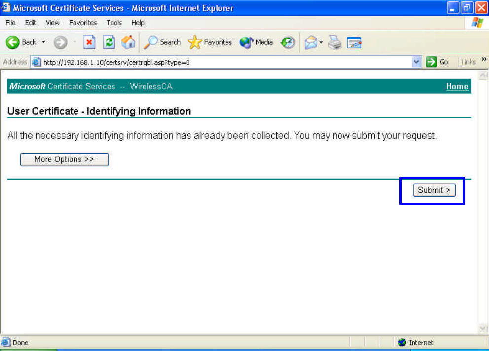
18. Click “Submit >” to continue.
49
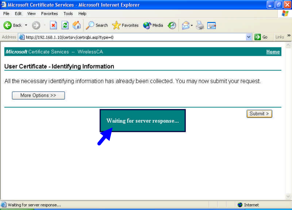
19. The Certificate Service is now processing the certificate request.