Global Sun Technology GL2411MUA Wireless Mini Size USB Adapter User Manual MINI USB MANUAL 121101
Global Sun Technology Inc Wireless Mini Size USB Adapter MINI USB MANUAL 121101
Manual

W
WI
IR
RE
EL
LE
ES
SS
S
M
MI
IN
NI
I
S
SI
IZ
ZE
E
U
US
SB
B
A
AD
DA
AP
PT
TE
ER
R
Version:1.0 Date:12/11/2001
1
Federal Communications Commission Statement
This device complies with FCC Rules Part 15. Operation is subject to the following two conditions:
This device may not cause harmful interference.
This device must accept any interference received, including interference that may cause undesired operation.
This equipment has been tested and found to comply with the limits for a Class B digital device, pursuant to Part
15 of the FCC Rules. These limits are designed to provide reasonable protection against harmful interference in a
residential installation. This equipment generates uses and can radiate radio frequency energy. If this equipment
is not installed and used in accordance with the manufacturer's instructions, it may cause harmful interference to
radio communications. However, there is no guarantee that interference will not occur in a particular installation. If
this equipment does cause harmful interference to radio or television reception, which can be determined by
during the equipment off and on, the user is encouraged to try to correct the interference by one or more of the
following measures:
Reorient or relocate the receiving antenna.
Increase the separation between the equipment and receiver.
Connect the equipment to an outlet on a circuit different from that to which the receiver is connected.
Consult the dealer or an experienced radio/TV technician for help.
The use of shielded cables for connection of the monitor to the graphics card is required to assure compliance
with FCC regulations. Changes or modifications to this unit not expressly approved by the party responsible for
compliance could void the user's authority to operate this equipment.
This equipment complies with FCC radiation exposure limits set forth for an uncontrolled environment. This
equipment should be installed and operated with minimum distance 20cm between the radiator and your body.
This transmitter must not be co-located or operating in conjunction with any other antenna or transmitter.
FCC RF Radiation Exposure Statement:
This equipment complies with FCC RF radiation exposure limits set forth for an uncontrolled environment. This
equipment should be installed and operated with a minimum distance of 20 centimeters between the radiator and
your body. This transmitter must not be co-located or operating in conjunction with any other antenna or
transmitter.
Manufacturer's Disclaimer Statement
The information in this document is subject to change without notice and does not represent a commitment on the
part of the vendor. No warranty or representation, either expressed or implied, is made with respect to the
quality, accuracy or fitness for any particular purpose of this document. The manufacturer reserves the right to
make changes to the content of this document and/or the products associated with it at any time without obligation
to notify any person or organization of such changes. In no event will the manufacturer be liable for direct,
indirect, special, incidental or consequential damages arising out of the use or inability to use this product or
documentation, even if advised of the possibility of such damages. This document contains materials protected
by copyright. All rights are reserved. No part of this manual may be reproduced or transmitted in any form, by
any means or for any purpose without expressed written consent of its authors. Product names appearing in this
document are mentioned for identification purchases only. All trademarks, product names or brand names
appearing in this document are registered property of their respective owners.
Printed in Taiwan
2
Contents
SECTION 1 ABOUT WIRELESS MINI-USB ADAPTER CARD………………………………………………..3
1-1 INTRODUCTION ..................................................................................................................................................................... 3
1-2 FEATURES .............................................................................................................................................................................. 3
1-3 APPLICATIONS ....................................................................................................................................................................... 3
1-4 PRODUCT KIT........................................................................................................................................................................ 4
SECTION 2 WIRELESS MINI-USB ADAPTER HARDWARE INSTALLATION……………………………..5
2-1 EQUIPMENT REQUIREMENT ................................................................................................................................................. 5
2-2 WIRELESS MINI-USB ADAPTER HARDWARE INSTALLATION ................................................................................ 5
2-3 WIRELESS MINI-USB ADAPTER SOFTWARE LIMITATION....................................................................................... 5
SECTION 3 SOFTWARE INSTALLATION AND CONFIGURING…………………………………………….6
3-1 MINI-USB ADAPTER DRIVER INSTALLATION - WINDOWS 98................................................................................6
3-2 MINI-USB ADAPTER DRIVER INSTALLATION - WINDOWS 2000 .................................................................................... 8
3-3 MINI-USB ADAPTER DRIVER INSTALLATION - WINDOWS ME…….. .......................................................................... 11
3-4 MINI-USB ADAPTER DRIVER INSTALLATION - WINDOWS XP..................................................................................... 13
3-5 CONFIGURING MINI-USB ADAPTER USING XP BUILT-IN UTILITY (XP ONLY)............................................ 15
3-6 CONFIGURING MINI-USB ADAPTER …………………………………........... ..................................................... 18
APPENDIX A NETWORK CONFIGURATION……………………………………………………………… .21
A-1 NETWORK TOPOLOGY....................................................................................................................................................... 21
Ad-Hoc Mode....................................................................................................................................................................... 21
Infrastructure ....................................................................................................................................................................... 22
A-2 ROAMING............................................................................................................................................................................ 23
APPENDIX B GLOSSARY………………………………………………………………………………………23
3
Section 1 About WIRELESS MINI SIZE USB ADAPTER CARD
1-1 Introduction
The WIRELESS MINI SIZE USB ADAPTER is a long-range, high performance LAN product, which
provides the connectivity with the access point to a 2.4 GHz RF network and bridges to an Ethernet backbone.
The design of this product is based on bridge -on-a-chip module, a highly integrated ASIC designed to
combine legacy LANs with wireless LANs. The Wireless MINI SIZE USB Adapter supports an
outside-the-box LAN connection for MINI SIZE USB-enabled PCs with excellent levels of security,
robustness and roaming features required for you business with a data rate up to 11Mbps. In
compatibility with MINI SIZE USB specification 1.1, this MINI SIZE USB adapter device also
provides energy-saving suspends mode and resume operations. It is a real plug-and-play,
Hot-swapping and simple test installation device with the support of full Microsoft network
security.
1-2 Features
–IEEE 802.11b Direct Sequence high data rate compatible
–Glueless connection to Intersil PRISM 2.5 Direct Sequence Spread Spectrum (DSSS) radio chip set. Able
to communicate also with other DSSS radios
–Supports 11 Mbps rates with automatic fallback to 5.5, 2 and 1 Mbps
–Advanced Power Management for power saving mode
–External Dipole antenna to increase the transmission power and receiving sensitivity
–Plug-and-Play installation
–WEP encryption/decryption is accomplished on the fly. 64/128 bit
–Glueless SRAM, Flash interface for data buffering and program storage, supporting up to 16 MB of
memory
1-3 Applications
The Serial of LAN products offer a fast, reliable, cost-effective solution, allowing clients to wirelessly
access the network in applications such as following:
1. Remote access to corporate network information
E-mail, file transfer and terminal emulation
2. Difficult-to-wire environments
4
Historical or old buildings, asbestos installations, and open area where wiring is difficult to employ
3. Frequently changing environments
Retailers, manufacturers and banks that frequently rearrange the workplace and change location
4. Temporary LANs for special projects or peak time
Trade shows, exhibitions and construction sites need temporary setup for a short time period. Retailers,
airlines and shipping companies need additional workstations for a peak period. Auditors require
workgroups at customer sites.
5. Access to database for mobile workers
Doctors, nurses, retailers, white-collar workers need access to database while being mobile in the hospital,
retail store or office campus.
6. SOHO (Small Office and Home Office) users
SOHO users need easy and quick installation of a small computer network.
1-4 Product Kit
u WIRELESS MINI SIZE USB ADAPTER ……………………………………………………….x 1
u External Dipole Antenna or Internal metal “L” type Antenna…………………………………x 1
u Driver\Utility CD.….………………………………………………………………..….……...…...x 1
u MINI SIZE USB cable……………………………………………………………….. …………….x 1
If any of the listed items are not included or found damaged, please contact your local dealer.

5
Section 2 WIRELESS MINI SIZE USB ADAPTER
Hardware Installation
2-1 Equipment Requirement
Installation of WIRELESS MINI SIZE USB ADAPTER requires
One PC with USB version 1.1 compliant interface
Windows
® 98, ME, 2000, XP OS Software CD, as Windows 95/NT do not support USB.
500 Kbytes free disk space for utility and driver installation.
2-2 WIRELESS MINI SIZE USB ADAPTER Hardware Installation
To install the wireless MINI SIZE USB ADAPTER, please connect one end of the MINI SIZE USB cable to
the device card first. Then connect the other end of MINI SIZE USB cable to the MINI SIZE USB port on the
desktop or laptop. The power LED should light up in green when the PC is on.
Adjust the direction of the antenna placement to improve the WIRELESS MINI SIZE USB Adapter’s
performance. Try to place the antenna in the position which can have the good connection to Access point.
Normally, the higher you place the antenna, the better the performance will be.
2-3 WIRELESS MINI SIZE USB ADAPTER Software Limitation
Before installing the MINI SIZE USB Adapter, please check that if your desktop or laptop is running on
Windows 98, ME, 2000 or XP Operating System .
Note!
Please note that Windows 95 / NT do
not support USB.
6
Section 3 Software Installation and Configuration
3-1 MINI SIZE USB Adapter Driver/Utility Installation - Windows 98
1. Ensure you have followed the procedure as described in the previous section to finish hardware installation.
Plug the two sides of the MINI SIZE USB cable into the MINI SIZE USB slots of MINI SIZE USB Adapter
and your PC.
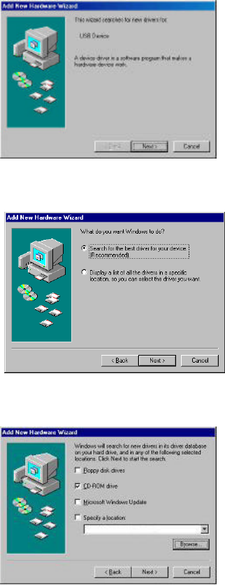
2. The Windows® will automatically detect the Wireless MINI SIZE USB Adapter and prompt you to install
the necessary driver. Please make sure that t he Setup Utility Driver CD is inserted into your CD ROM
drive and click “Next” to begin the installation.
3. Select “Search for the best driver for your device…” and click “Next”.
4. Select “CD-ROM drive”. Windows® will automatically find the file. Then click “Next”.
7
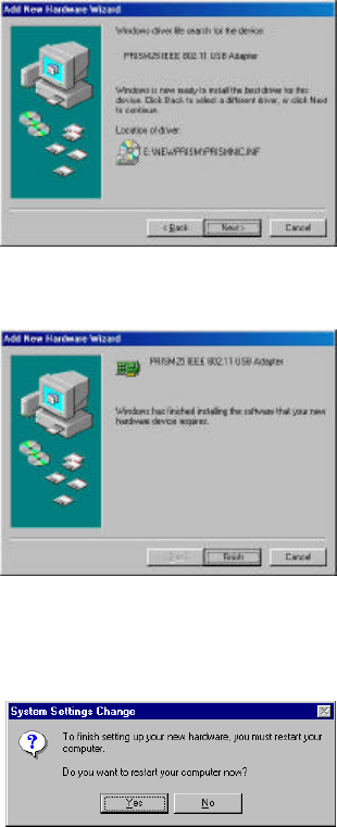
5. The Windows® will then acknowledge that it has found the appropriate driver and click "Next".
6. Windows® will install the driver and finish the installing.
7. After Windows has finished installing the appropriate files and will ask you to restart your computer.
Please just click “Yes”.
8
3-2 MINI SIZE USB Adapter Driver/Utility Installation -Windows® 2000
1. Ensure you have followed the procedure as described in the previous section to finish
hardware installation. Plug the two sides of the MINI SIZE USB cable into the MINI SIZE USB
slots of MINI SIZE USB Adapter and your PC.
2. The Windows® will automatically detect the Wireless MINI SIZE USB Adapter and prompt you to
install the necessary driver. Please make sure that the Setup Utility Driver CD is inserted into your
CD ROM drive.
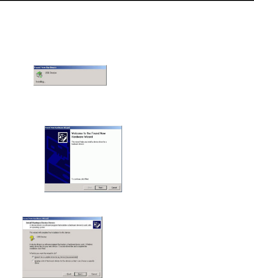
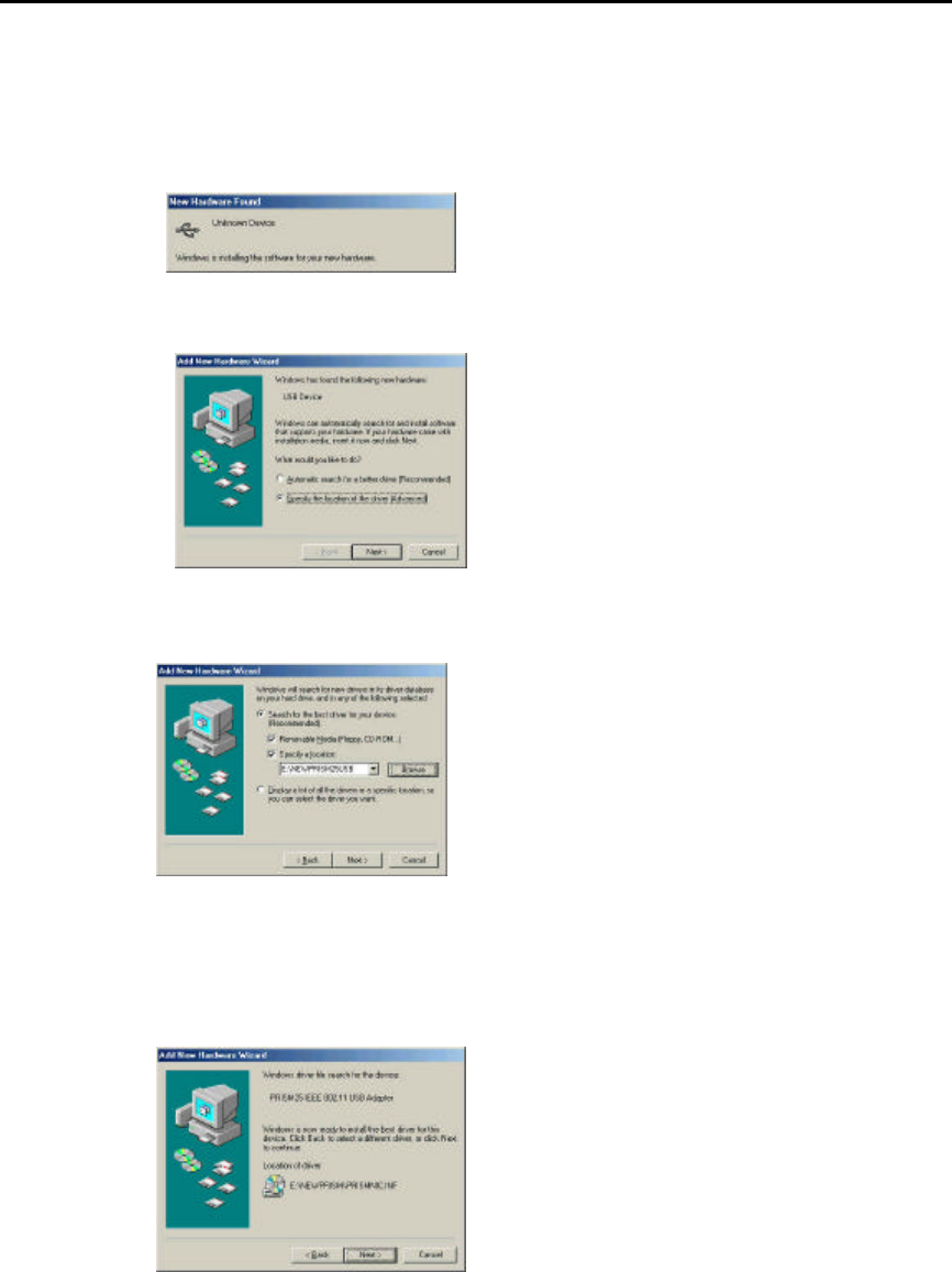
3. Windows® 2000 will automatically detect the MINI SIZE USB Adapter and prompt you to
install t he necessary driver. Click “Next” to begin the installation.
4. Select “Search for a suitable driver…” and click “Next” to find the GL2411V1-A driver.
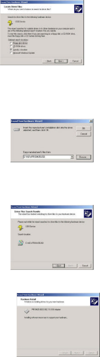
5. Select “Specify a location” and click “Next”.
9
6. Make sure driver CD is in the drive. Then type in “ E:\NEWPRISM25USB ” and click “OK”
Where E: is your CD-ROM drive.
7. Windows® 2000 will automatically scan the driver. After acknowledge of Windows® 2000,
please click "Next".
8. Windows® 2000 is installing the software to support the hardware.
10
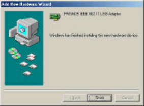
9. Windows® 2000 will install both the driver and the utility. Then Windows® 2000 will show
a windows information dialog. Click “Finish”.
11
3-3 MINI SIZE USB Adapter Driver/Utility Installation - Windows® Me
1. After inserting the MINI SIZE USB Adapter into a USB slot and powering on the PC under
Windows
® Me, Windows® Me will automatically detect the MINI SIZE USB Adapter and
prompt you to install the necessary driver. Check “Specify the location of the driver
(Advanced)” and click “Next” to begin the installation.
2. Insert the Driver \Utility CD. Check “Specify a location” and browse
“E:\NEWPRISM25USB ” folder. Then click “Next”. ( “E” represents the CD-ROM drive)
3. Windows® Me will install the driver. As the driver files are being copied to the appropriate
location, you will be prompted to insert the Windows® ME CD.
12
4. After installation, please click "Finish"
13
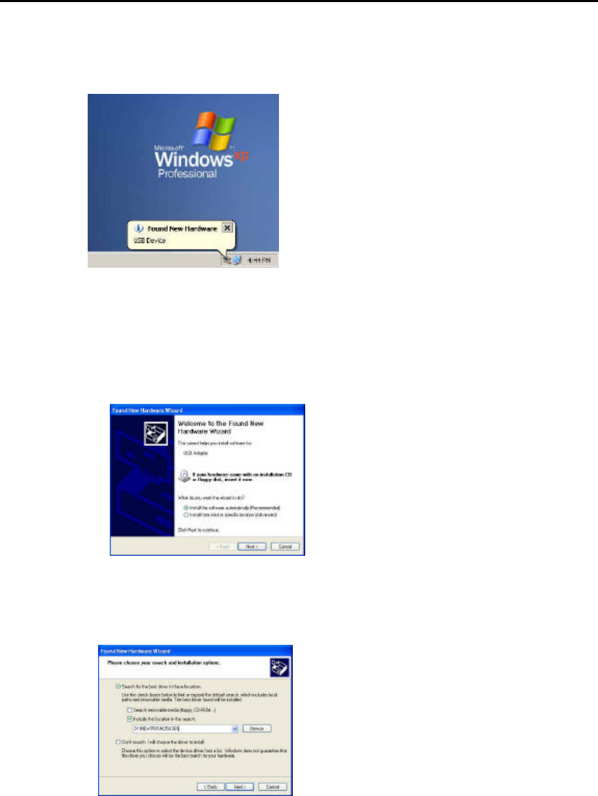
3-4 MINI SIZE USB Adapter Driver/Utility Installation -Windows® XP
1. After inserting the MINI SIZE USB Adapter into a USB slot and powering on the PC under
Windows
® XP, Windows® XP will automatically detect the adapter and prompt you to install the
necessary driver.
2. Check “Specify the location of the driver (Advanced)” and click “Next” to begin the
installation.
3. Insert the Driver\Utility CD. Check “Include this location for the search” and browse
“D:\NEWPRISM25USB ” folder. Then click “Next”. (where “D” represents the CD-ROM
drive)
14
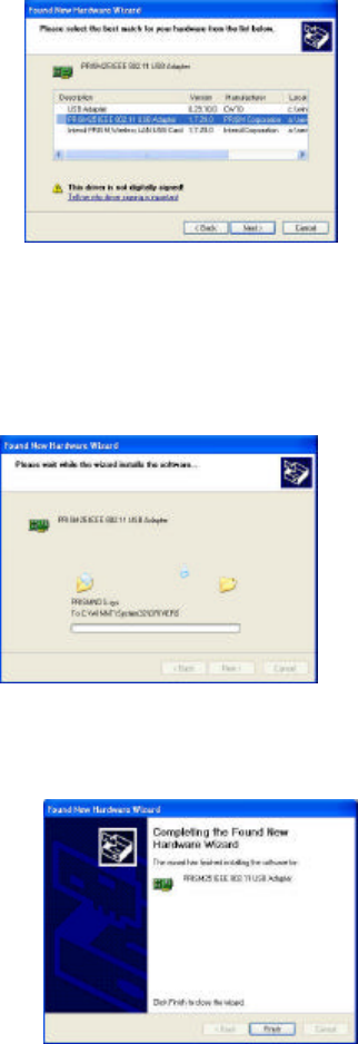
4. Select “Prism25 IEEE 802.11 USB Adapter” from the list and click “Next ” to continue.
5. Windows® XP will install the driver. As the driver files are being copied to the appropriate
location.
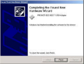
6. After installation, please click "Finish"
15
3-5 Configuring the Mini-Size USB Adapter using XP Built-in Utility
(XP only)
Note: Windows XP has its built-in configuration utility. You may use it to configure the
Mini-Size USB Adapter instead of the utility that came with the adapter.
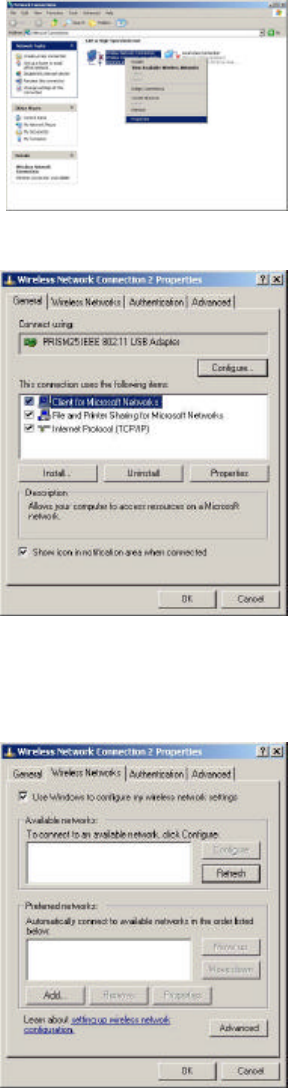
1. Right click “My Network Places ” and select “Properties”.
2. Right click “Wireless Network Connection” icon.
3. Select “Wireless Networks” Tab.
You may click “Refresh” if you currently have existing wireless network and need to search for it .
16
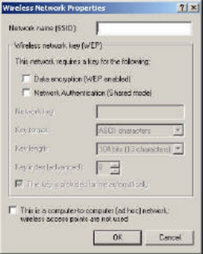
You may also click “Add” to add your adapter to the existing network.
SSID: The SSID is the name shared among all points in a wireless network system. The network name is
also known as a Service Set Identifier. The SSID must be identical with the Access Point in a
“Infrastructure” mode. If choosing “Ad Hoc”, all clients should share all the same SSID name, make sure
you check the box for “This is a computer-to-computer (ad hoc) network; wireless access points are
not used”. After changing, please click “ Ok” to continue.
You may check the box for “Data encryption (WEP enabled)” to encrypt the data.
Data Encryption (WEP enabled) : Specifies whether Wired Equivalent Privacy (WEP) is enabled for this
preferred wireless network. If this check box is selected, a network key is used to encrypt your data while
it is transmitted over the network. WEP is a set of security services used to protect 802.11 wireless
networks from unauthorized access.
Network Authentication (Shared mode ): Specifies whether a network key is used to authenticate to this
preferred wireless network. Under 802.11 standard for wireless networks, when a network key is used for
authentication, the network is operating in Shared Key authentication mode. If a network key is not used
for authentication, the network is operating in Open System mode.
By default the box for “The key is provided for me automatically” is being checked. If you would like
to enter the key yourself, uncheck the box and enter the Network Key for the existing network. The Key
format can be either “ASCII characters” or “Hexadecimal digits”. And for the key length, you can either
select “40 bits ” for 5 characters or “104 bits ” for 13 characters.
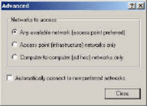
You may click on “Advanced” button to select:
-Any available network (access point preferred)
-Access point (infrastructure) networks only.
-Computer-to-computer (ad hoc) networks only
or
check the box for “Automatically connect to non-preferred networks ”
17
18
3-6 Configuring MINI SIZE USB ADAPTER
Note: The utility software will be installed at the same time while installing the drivers.
After the driver installation, an icon will appear on the task bar on the right.
1. Double click the icon to execute the program.
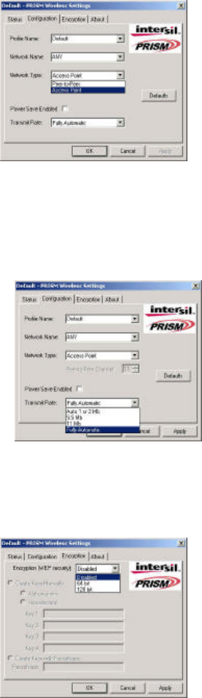
2. The “Status ” Tab, it will show the Wireless Network MINI SIZE USB Adapter current connection. Click
“OK” to close the Configuration Utility.
Disable Radio: means to disable the usage of radio frequency.
Rescan: means to allow the device to rescan all the other station s or Access Points on the existing wireless
networks.
3. The “Configuration” Tab, you can change Profile Name, Network Name, Network Type and
Transmit Rate.
Profile Name : is for you to choose different profiles which were saved in various configurations.
Network Name: means you are able to select different ESSID names or Group name that you have
created and saved.
19
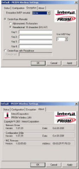
Network Type: The choices are “Access Point ” or “Peer to Peer”. The default is set to “Access Point ”.
Transmit Rate: The selections are “Auto 1 or 2Mb”, “5.5Mb”, “11Mb” or “Fully Automatic”. The
default is set to “Fully Automatic” so the device will perform auto fall back to justify the actual through
put of the network.
5. The “Encryption” Tab, .under the drop box the user can select to have WEP Encryption Disabled, 64 bit
or 128 bit.
Enter WEP Key Setting. This setting key is to configure the WEP encryption in the wireless network system.
To generate the key, please insert the same PassPhrase in the field and click the “Done” to create the
encryption key which must be same as the every point on the Wireless Network system. Then Click the
“Apply” to store the setting keys.
20
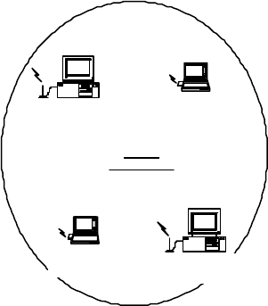
6. The “About” Tab, is to show the copyright and version information about the driver, utility and firmware.
21
Appendix A Network Configuration
A-1 Network Topology
Ad -Hoc Mode
Desktop PC
with
Wireless USB Adapter
Desktop PC
with
Wireless USB Adapter
Notebook
with
Wireless USB Adapter
Notebook
with
Wireless USB Adapter
Ad Hoc
Wireless LAN
Fig. 1 - Ad-Hoc Wireless LAN
An Ad-Hoc wireless LAN is a group of computers, each equipped with one LAN adapter, connected as
an independent wireless LAN. Computers in a specific Ad-Hoc wireless LAN must be configured at the
same radio channel and ESSID.
Ad-Hoc wireless LAN is applicable at a departmental scale for a branch or SOHO operation.
22
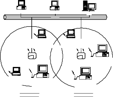
Infrastructure
Ethernet
Desktop PC with ethernet Desktop PC with ethernet Sever
Access Point Access Point
Notebook
with
Wireless USB Adapter
Notebook
with
Wireless USB Adapter
Notebook
with
Wireless USB Adapter
Desktop PC
with
Wireless USB Adapter
Desktop PC
with
Wireless USB Adapter
Desktop PC
with
Wireless USB Adapter
Infrastructure
Wireless LAN Infrastructure
Wireless LAN
Fig. 2 An Example of Infrastructure Wireless LAN
Access Point provides access to a wired LAN for wireless workstations. An integrated wireless and wired
LAN is called an Infrastructure configuration. A group of LAN PC users and an Access Point construct a
Basic Service Set (BSS). Each LAN PC in the BSS can talk to any computer in the wired LAN
infrastructure via the Access Point.
Infrastructure configuration not only extends the accessibility of a LAN PC to the wired LAN, but also
doubles the effective wireless transmission range for 2 LAN PCs. Since the Access Point is able to
forward data within its BSS, the effective transmission range in an infrastructure LAN is doubled.
BSS ID is, in essence, the ID of each independent Access Point. All LAN PCs configured without
roaming options in the independent BSS must be configured with the BSS ID of the Access Point.
Infrastructure is applicable in an enterprise scale for wireless access to central databases, or wireless
access for mobile workers.
23
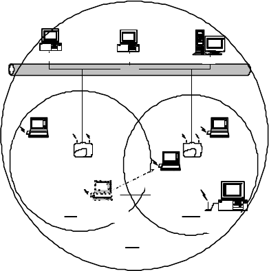
A-2 Roaming
Ethernet
Desktop PC with ethernet Desktop PC with ethernet Sever
Access Point Access Point
Notebook
with
Wireless USB Adapter
Notebook
with
Wireless USB Adapter
Notebook
with
Wireless USB Adapter
Desktop PC
with
Wireless USB Adapter
BSS1 BSS2
ESS
Notebook
with
Wireless USB Adapter
Roaming
Fig. 3 Roaming in an Extended Service Set (ESS)
An Infrastructure configuration also supports roaming capability for mobile workers. More than one BSS can
be configured to be an Extended Service Set (ESS). On account of a continuous connect ion to the network,
users within an ESS can roam freely. All LAN PCs and Access Points within one ESS must be configured
with the same ESS ID and at the same radio channel.

24
Appendix B Glossary
Access Point An internetworking device that seamlessly conn ects wired and wireless networks.
Ad-Hoc An Ad-Hoc wireless LAN is a group of computers each with LAN adapters, connected as an
independent wireless LAN.
Authentication Type Indication of an authentication algorithm which can be supported by this node:
1. Open System: Open System authentication is the simplest of the available authentication algorithms.
Essentially it is a null authentication algorithm. Any station that requests authentication with this
algorithm may become authenticated if dot11Authent icationType at the recipient station is set to Open
System authentication.
2. Shared Key : Shared Key authentication supports authentication of STAs as either a member of those
who know a shared secret key or a member of those who do not.
Open System authentication is the default authentication algorithm.
Backbone The core infrastructure of a network. The portion of the network transports information from one
central location to another central location where it is un loaded onto a local system.
Basic Rate the data rate of the AP with the value 1,2,5.5 or 11 Mbps for your selection.
Bridge An internetworking function that incorporates the lowest 2 layers of the OSI network protocol model.
BSS BSS stands for “Basic Service Set”. It is an Access Point and all the LAN PCs that associated with it.
Channel The AP and the with it associated stations will work in this channel. You must set the channel by
consult ing Appendix B from violating the Specifications.
DSSS direct sequence spread spectrum
ESS ESS stands for “Extended Service Set”. More than one BSS is configured to become Extended Service Set.
LAN mobile users can roam between different BSSs in an ESS.
ESSID In infrastructure association , the stations will link to the AP with the same ESSID as they have.
Ethernet A popular local area data communications network, originally developed by Xerox Corp., that accepts
transmission from computers and terminals. Ethernet operates on a 10 Mbps base band transmission rate, using a
shielded coaxial cable or over shielded twisted pair telephone wire.
Ethernet IP Address and Subnet Mask Please setup them to match your network environment.
For example: If your IP address is 192.168.99.127 and your Subnet Mask is 255.255.255.0. Please set
the IP address of the AP to 192.168.99.xx which will not have conflict with other IP

25
address and set the Subnet Mask of the AP to 255.255.255.0.
Ethernet Mac Address Don’t change it, as this will disable the AP.
Infrastructure An integrated wireless and wired LAN is called an Infrastructure configuration.
PLCP physical layer convergence protocol
PPDU PLCP protocol data unit
Preamble Type During transmission, the PSDU shall be appended to a PLCP preamble and header to create the
PPDU. Two different preambles and headers are defined : the mandatory supported long preamble and header
which interoperates with the current 1 and 2 Mbps DSSS specification as described in IEEE Std 802.11-1999, and
an optional short preamble and header. At the receiver, the PLCP preamble and header are processed to aid in
demodulation and delivery of the PSDU. The optional short preamble and header is intended for application where
maximum throughput is desired and interoperability with legacy and non short preamble capable equipment is not
consideration. That is, it is expected to be used only in networks of like equipment that can all handle the optional
mode. (IEEE 802.11b standard)
PSDU PLCP service data unit
Roaming A LAN mobile user moves around an ESS and enjoys a continuous connection to the Infrastructure
network.
RTS Threshold Transmitters contending for the medium may not be aware of each other. RTS/CTS mechanism
can solve this “Hidden Node Problem”. If the packet size is smaller than the preset RTS Threshold size, the
RTS/CTS mechanism will NOT be enabled.
WEP – “Wired Equivalent Privacy ” WEP is an encryption scheme used to protect wireless data communication to
enable the icon will prevent other stations without the WEP key from linking with the AP.