Global Sun Technology GL2411RT-0B Access Point User Manual GL2411RT 0B 4
Global Sun Technology Inc Access Point GL2411RT 0B 4
UserManual.wiki
>
Global Sun Technology
>
GL2411RT-0B User Manual
>
Users Manual Part 1
Contents
1.
Users Manual Part 1
2.
Users Manual Part 2
3.
DoC Statement
4.
Users Manual Part 3 revised
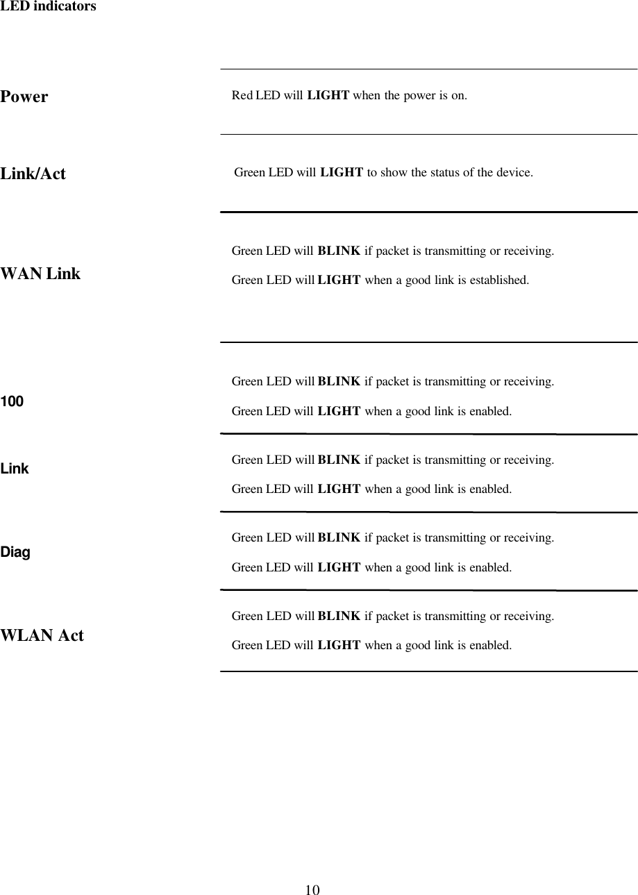
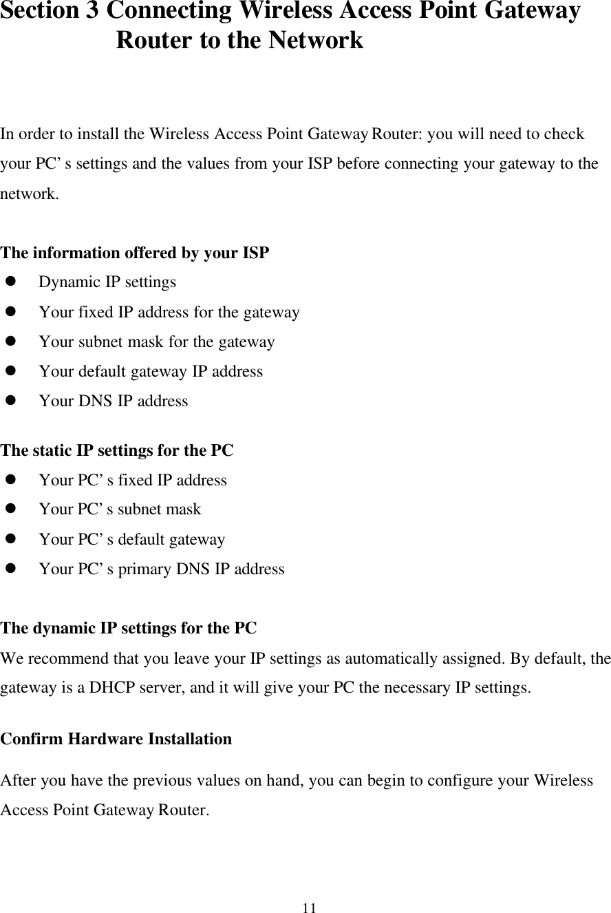
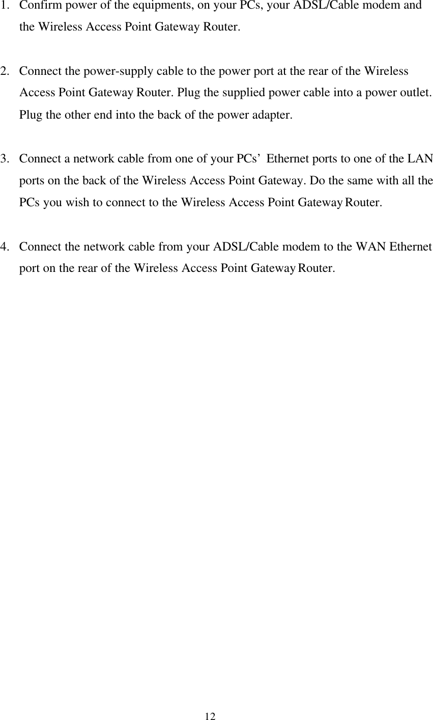
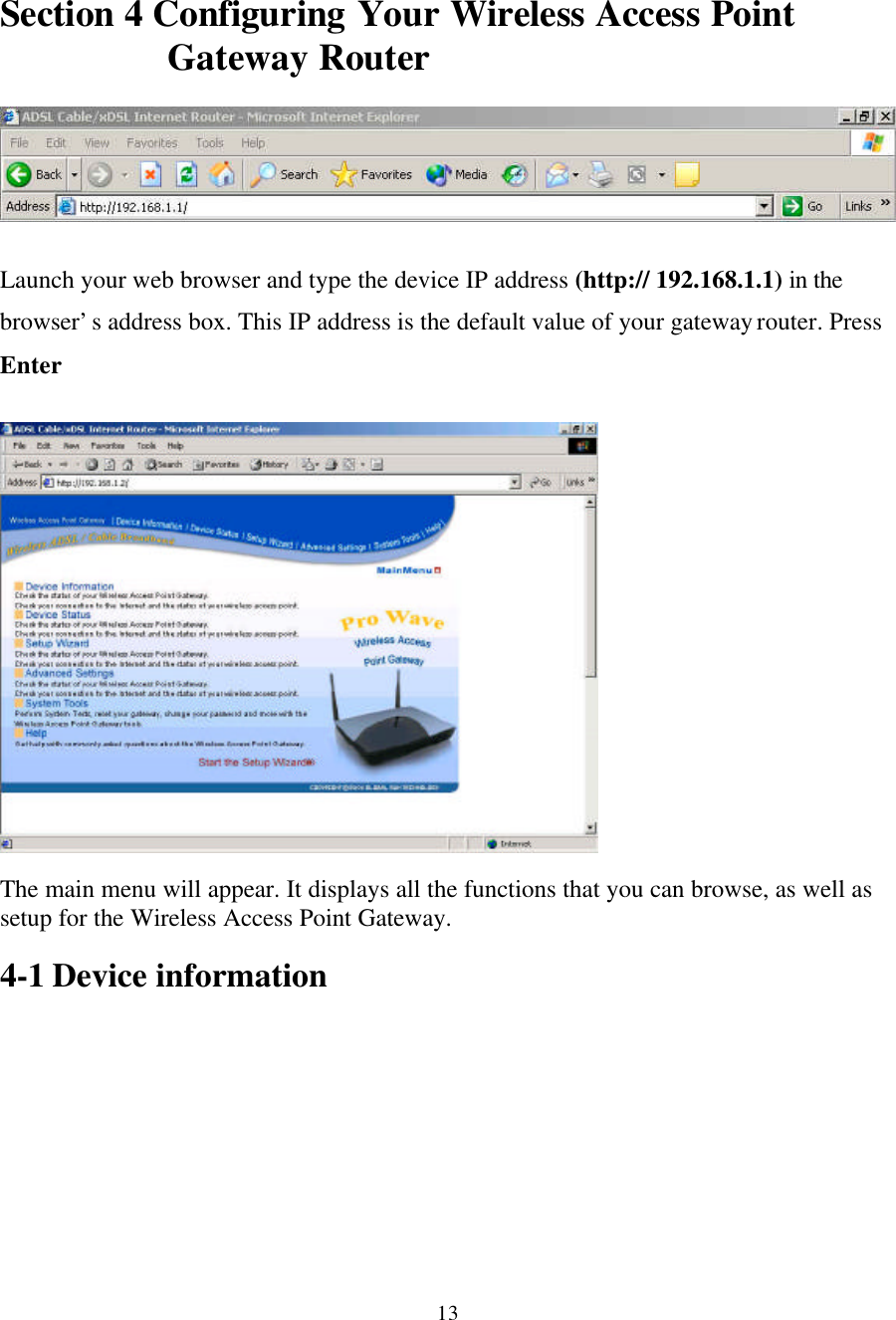
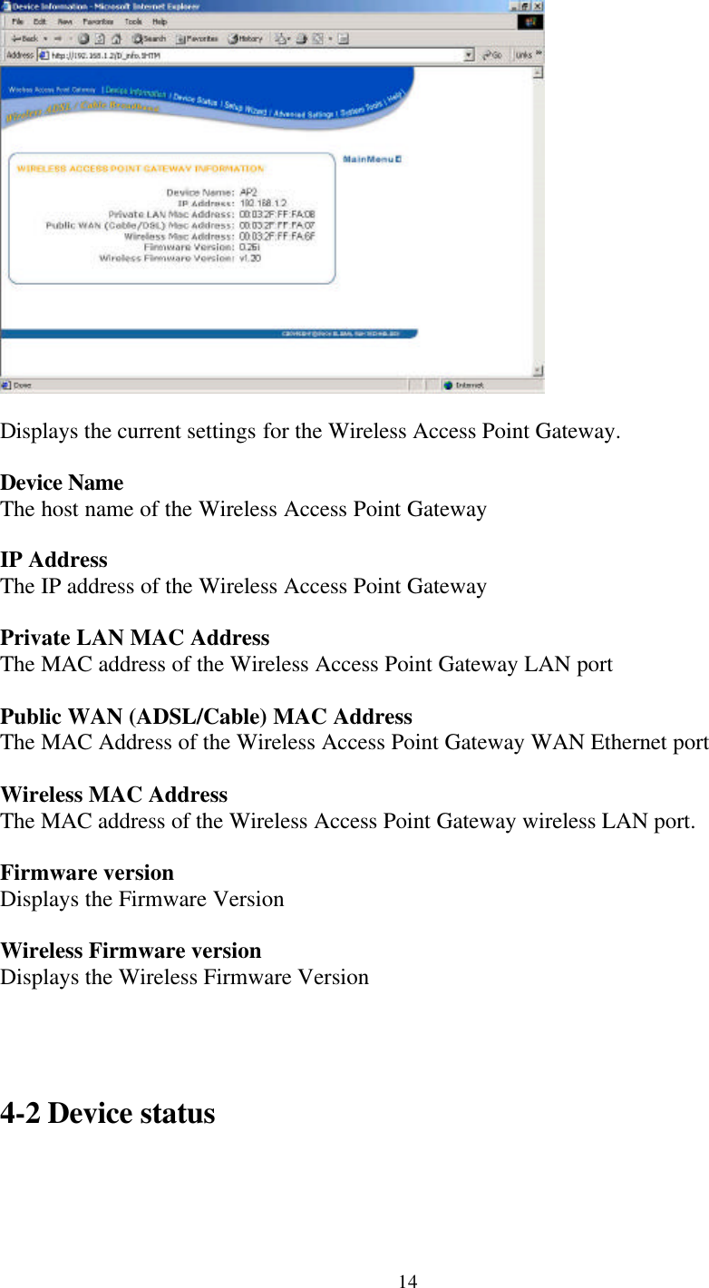
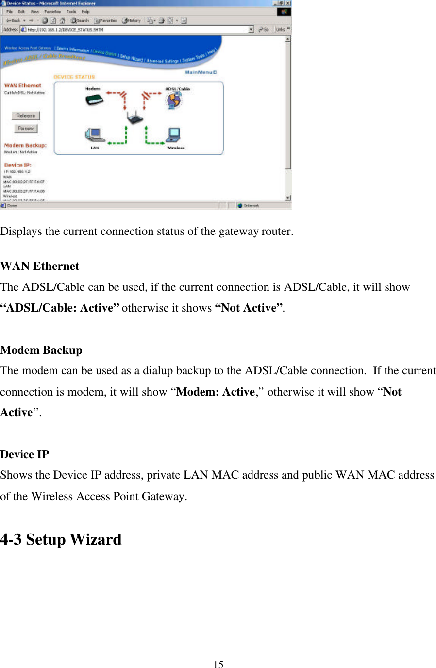
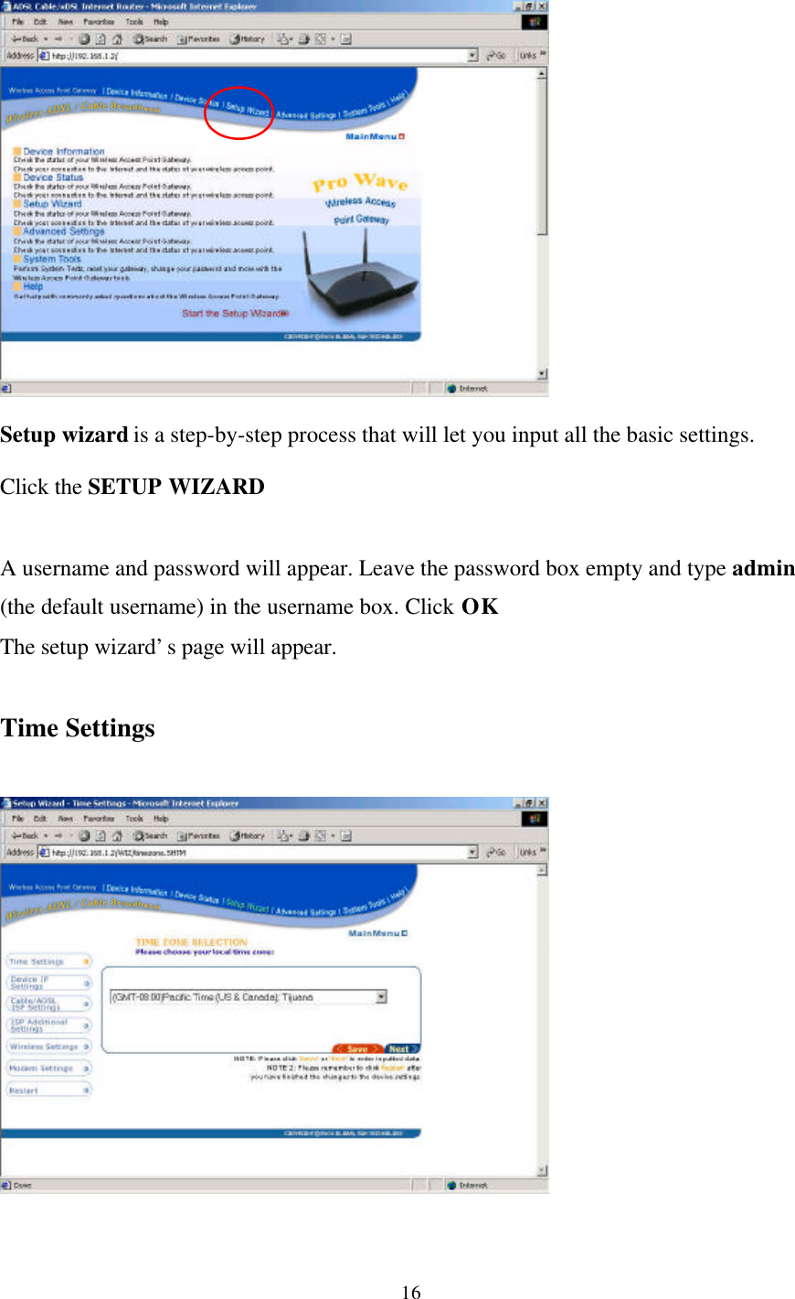
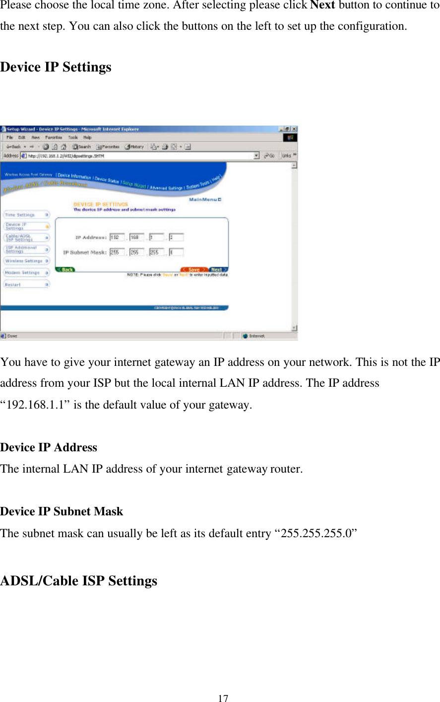
Users Manual Part 1
Navigation menu
Upload a User Manual
Namespaces
Wiki Guide
HTML
PDF
Info
Views
User Manual
Discussion / Help
Navigation