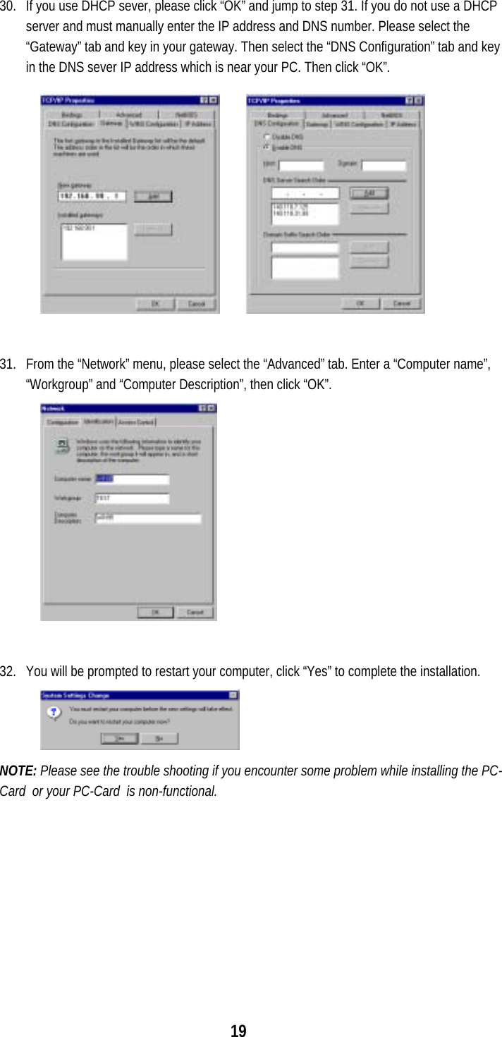
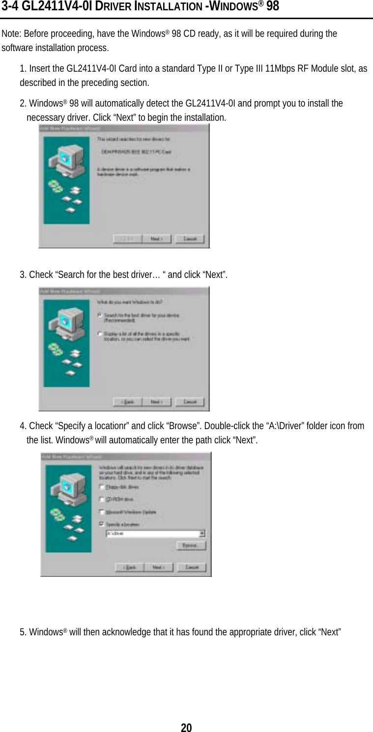
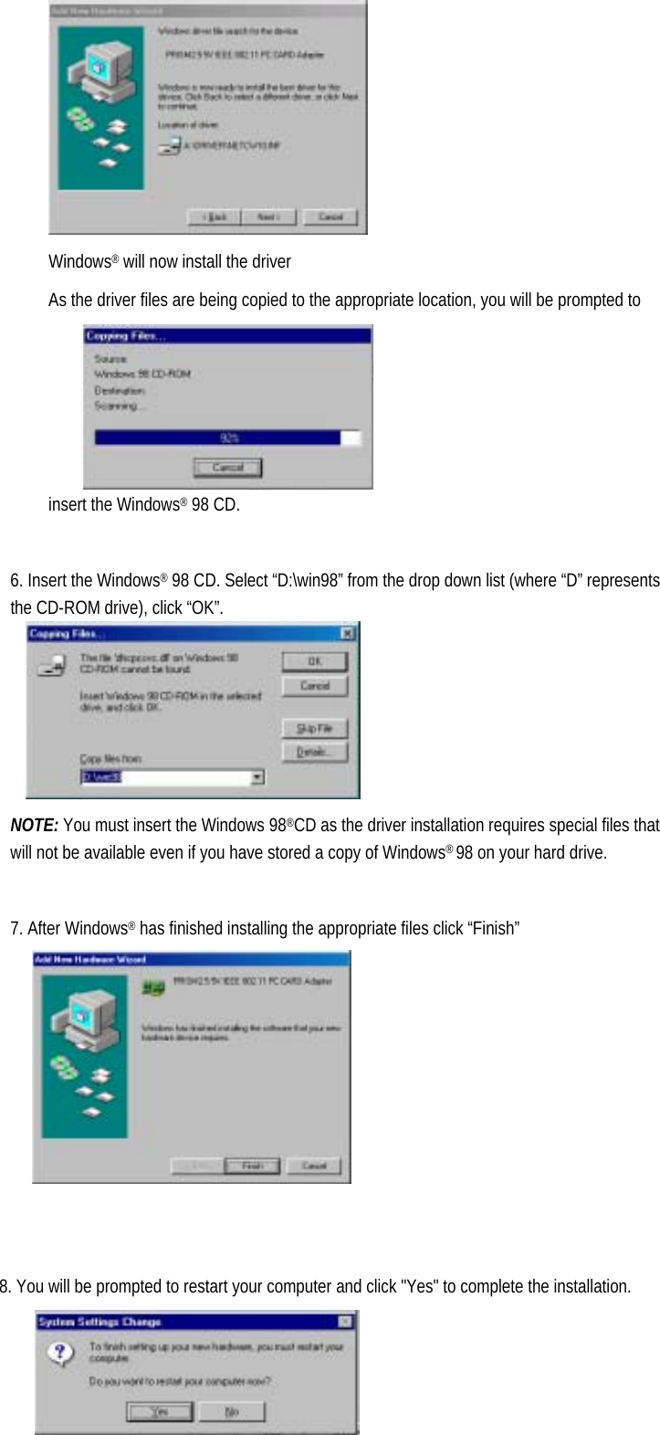
Global Sun Technology GL2411V4-0I Wireless 11Mbps PCMCIA RF Module User Manual users manual
Global Sun Technology Inc Wireless 11Mbps PCMCIA RF Module users manual
UserManual.wiki
>
Global Sun Technology
>
GL2411V4 0I User Manual
users manual
Navigation menu
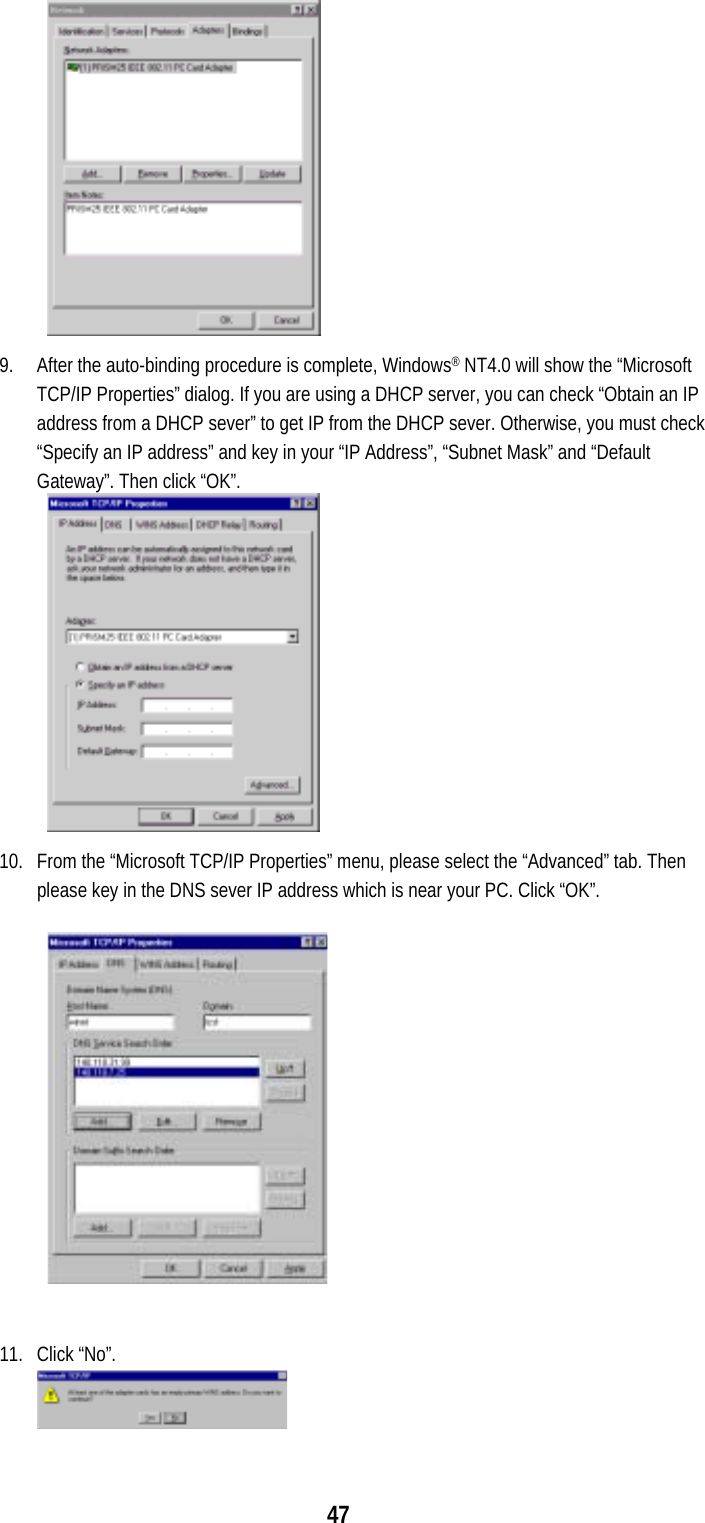
Upload a User Manual
Namespaces
Wiki Guide
HTML
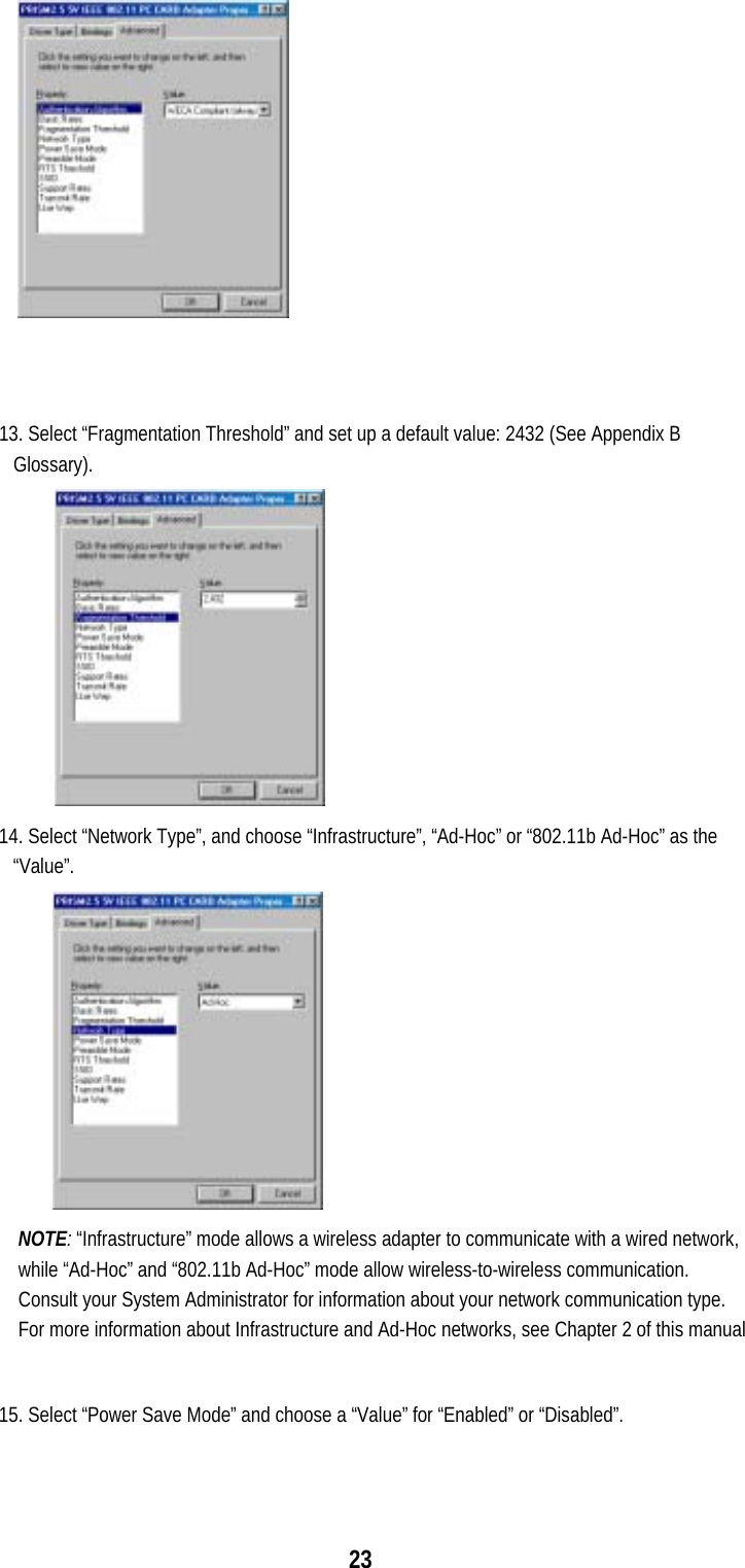
PDF
Info
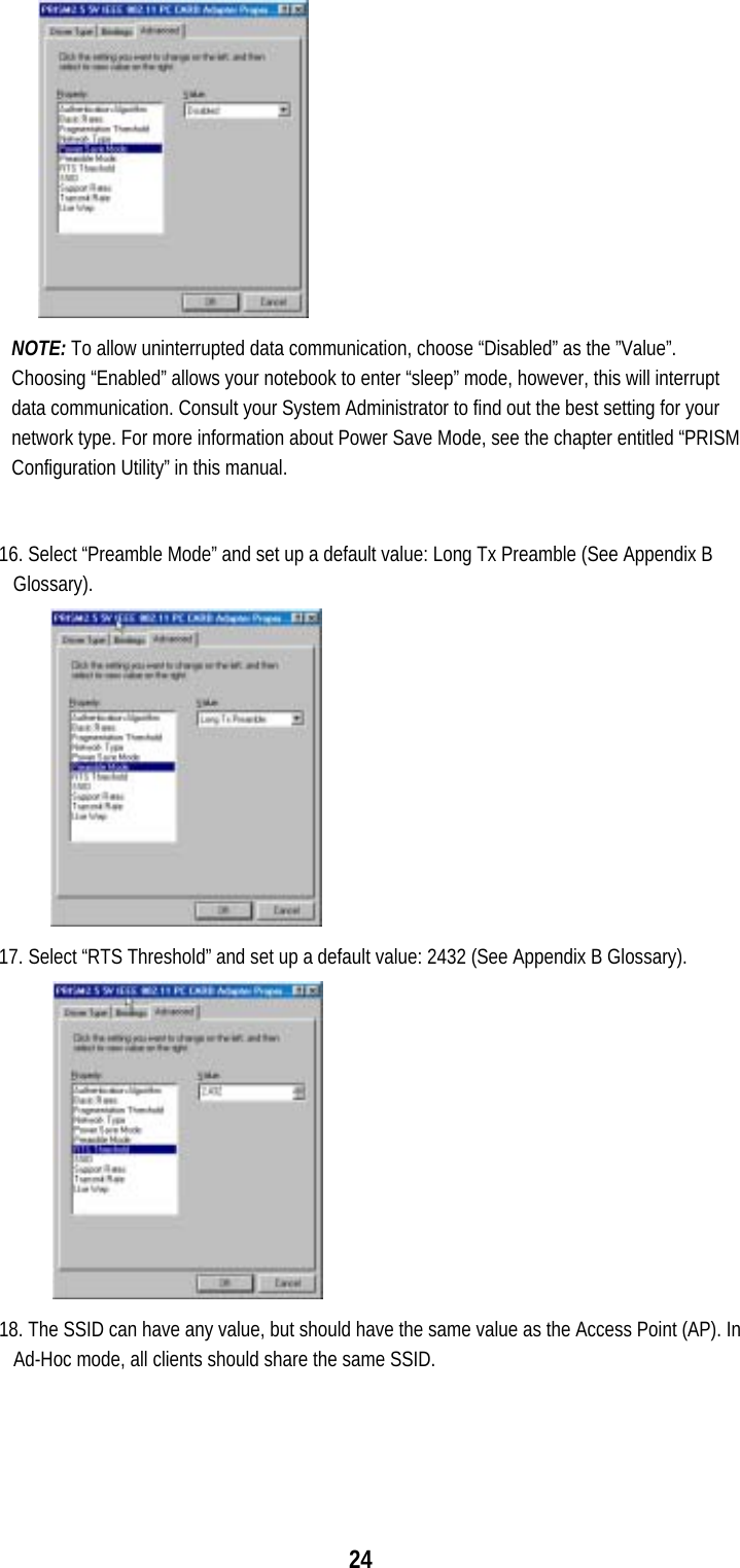
Views
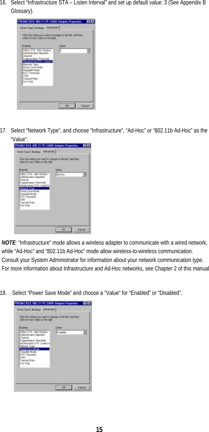
User Manual
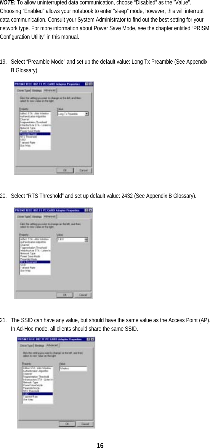
Discussion / Help
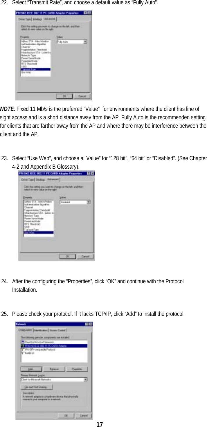
Navigation

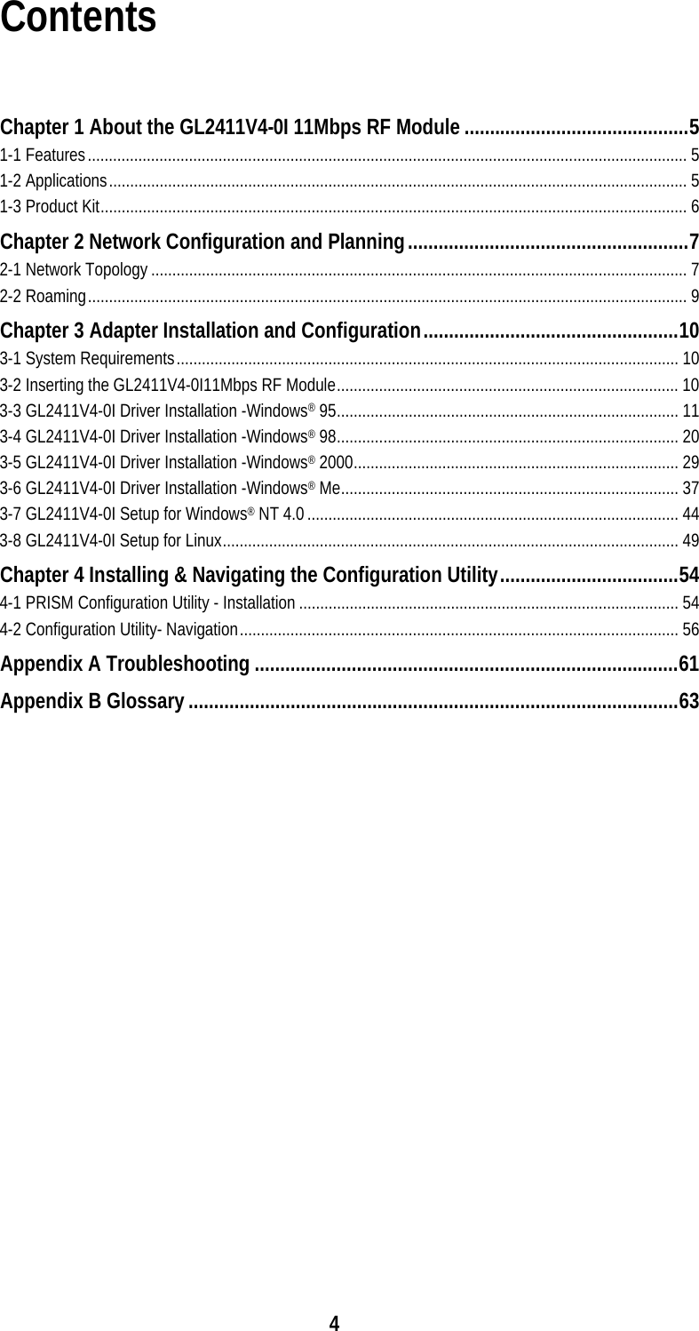
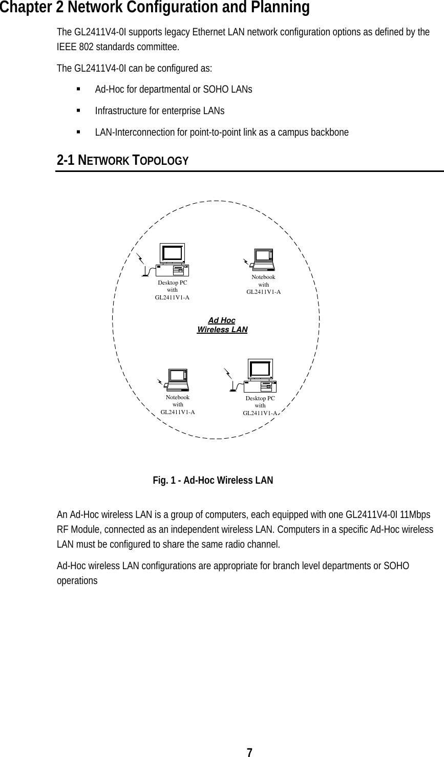
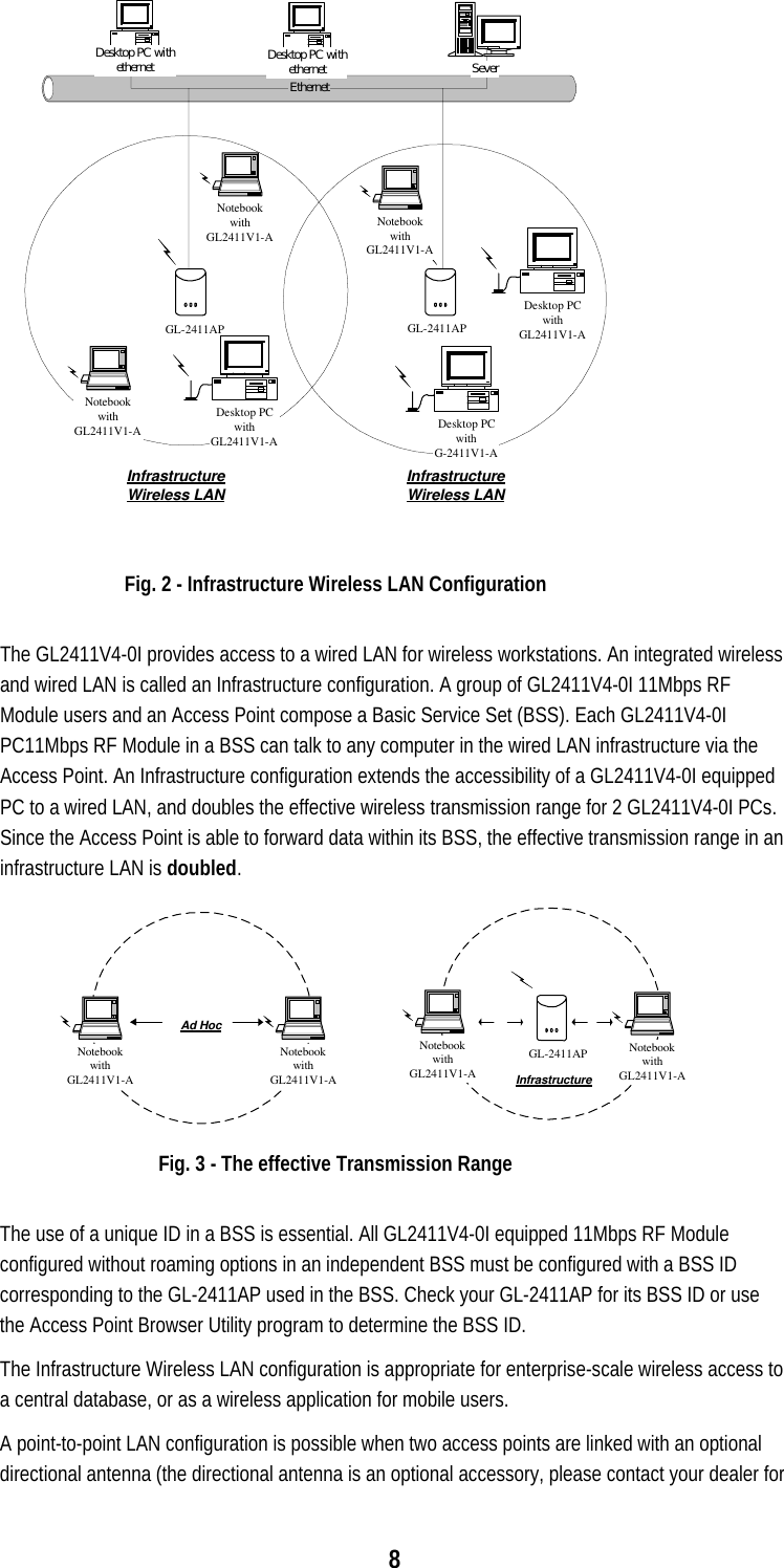
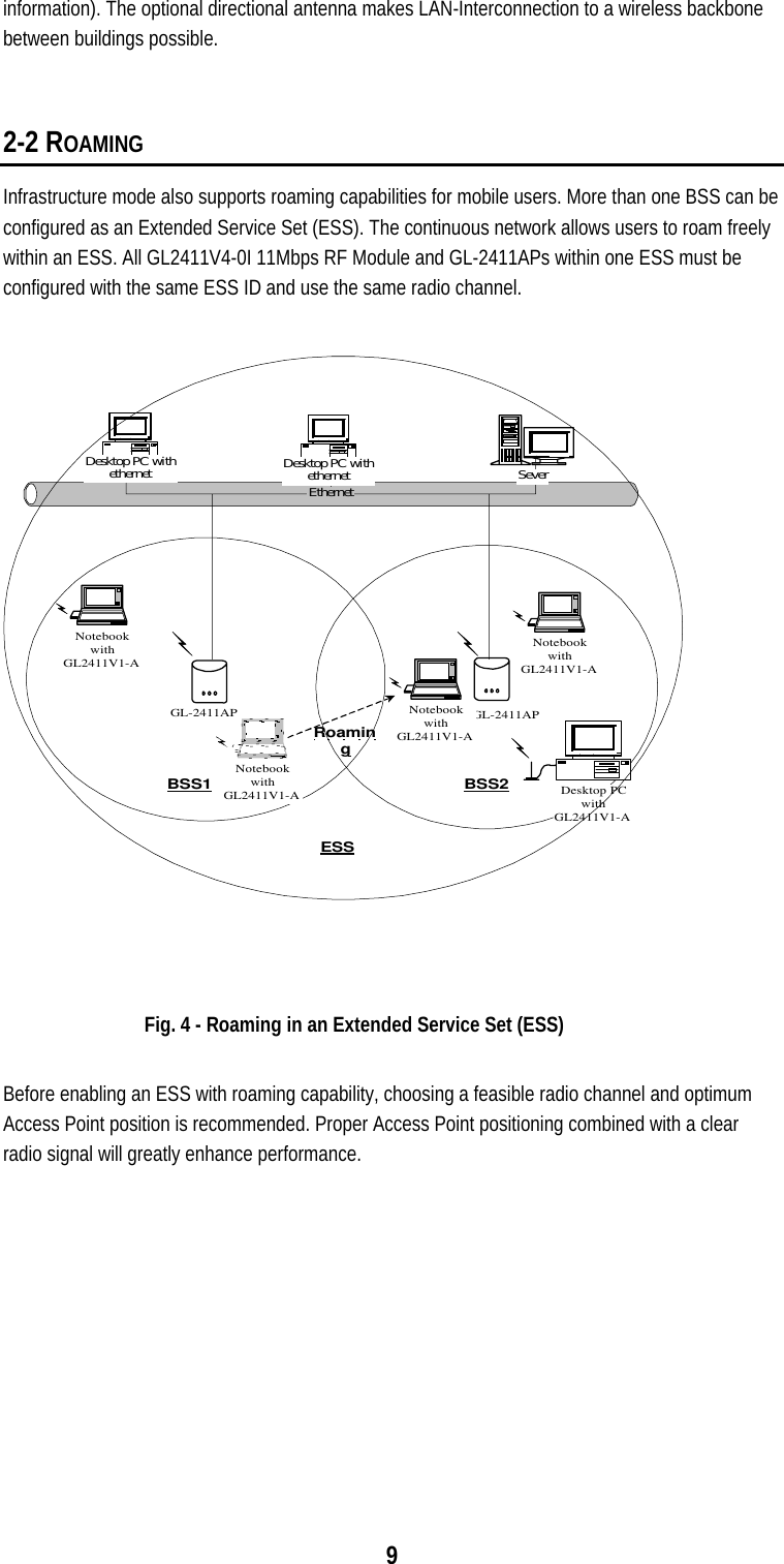
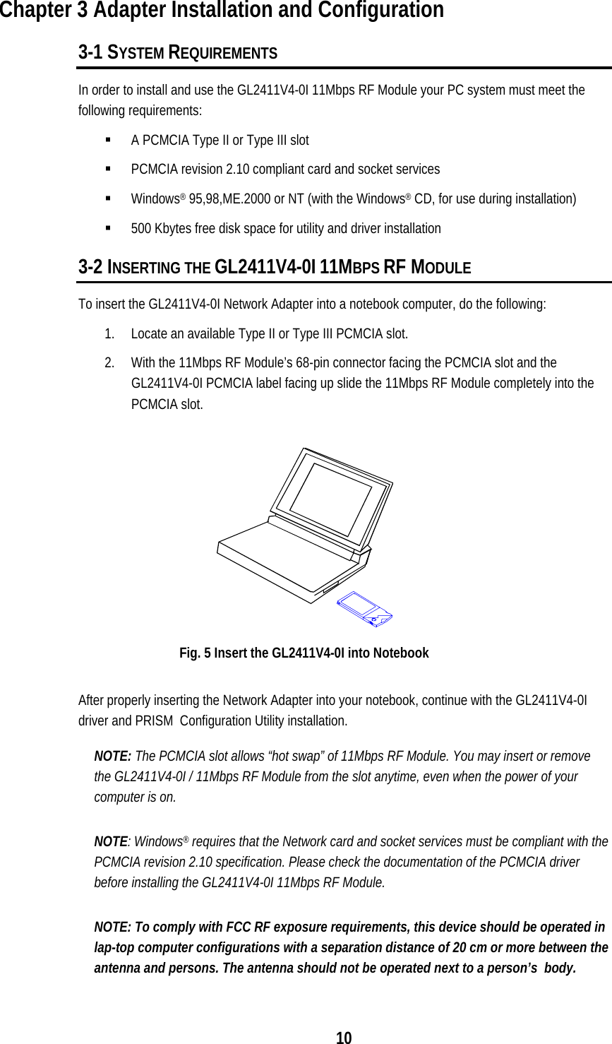
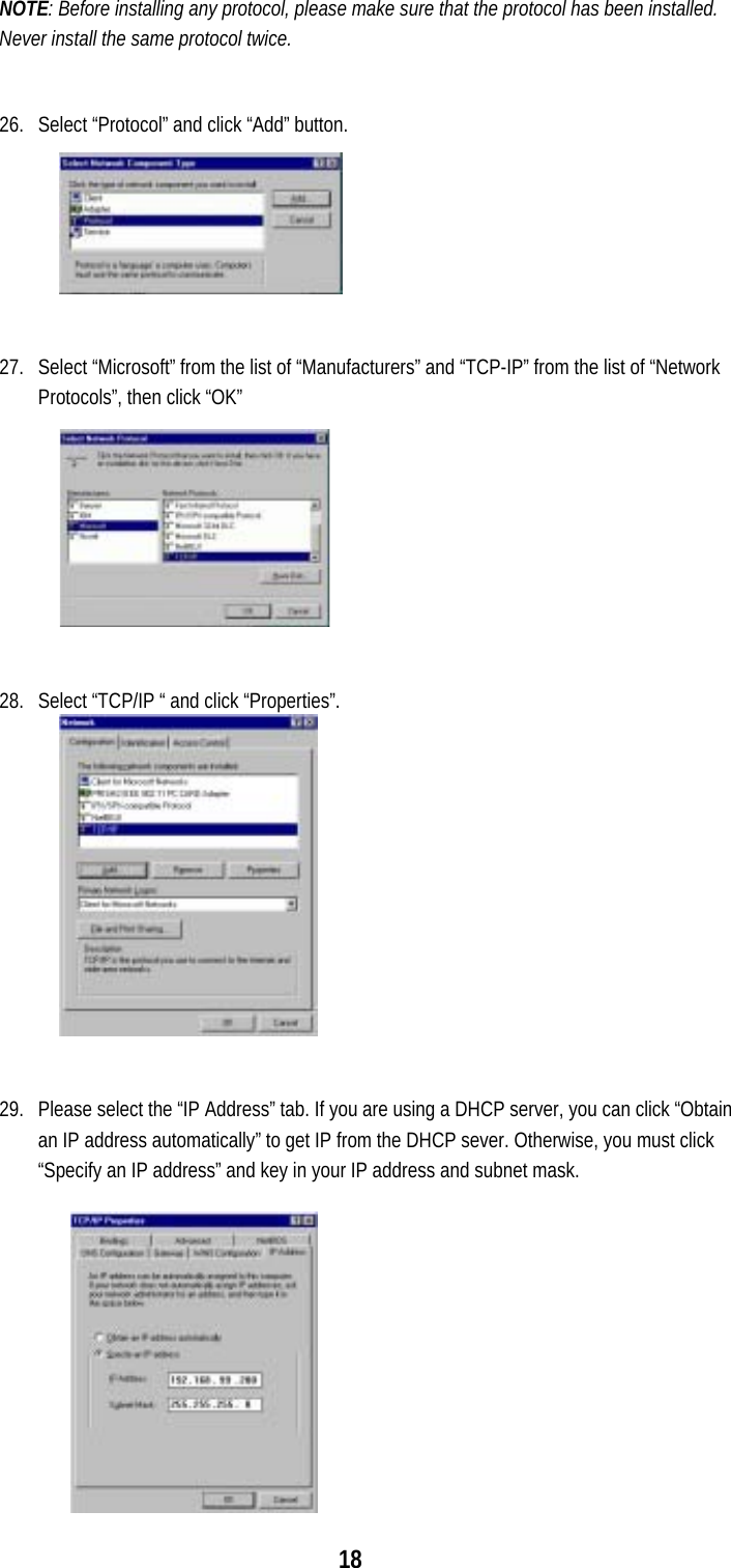
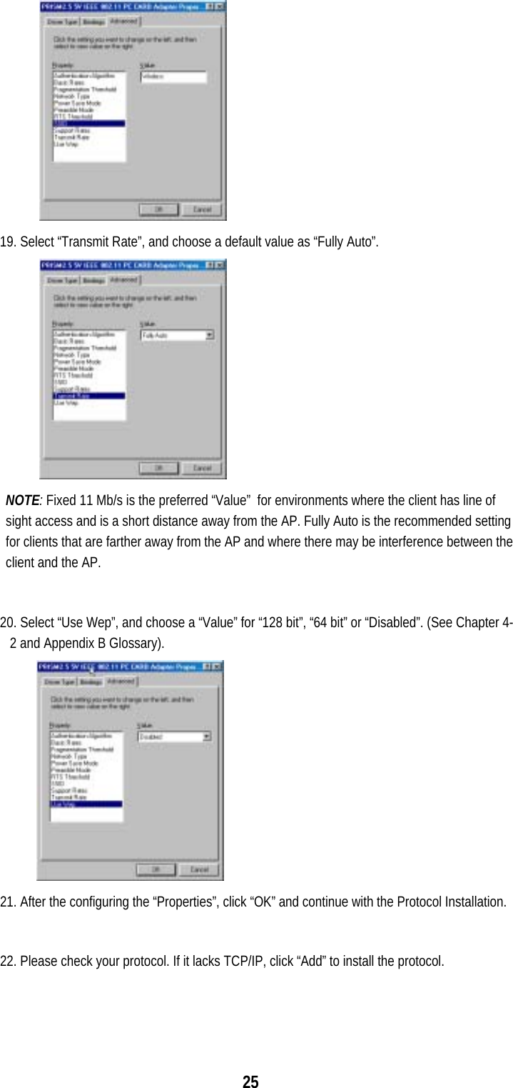
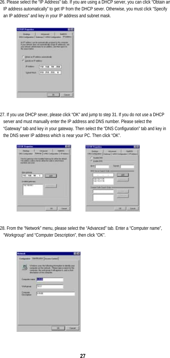
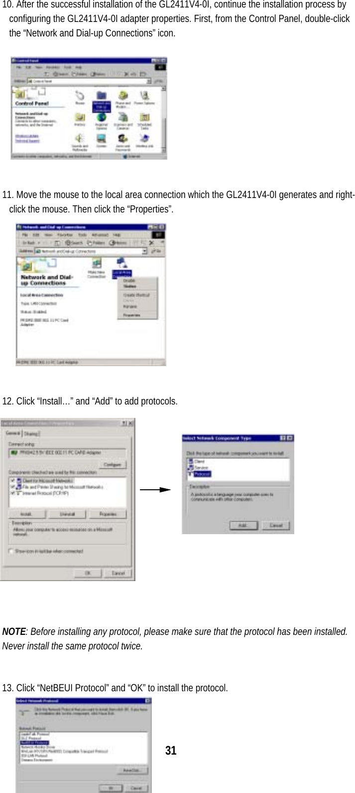
![51 8) # make config. To configure the linux-wlan-ng-0.1.7 package, run 'make config.' and respond to the questions. The defaults should be sufficient for most users. 'make config.' must be run after a 'make clean' and before 'make all'. 9) To build the package. # make all 10) To install the package. # make install 11) Edit the /etc/pcmcia/wlan-ng.opts file for configuration. These options are set every time you insert a card. # cd /etc/pcmcia # vi /etc/pcmcia/wlan-ng.opts ; Do we want to enable the card at all? It always sets to 'y'. ; Set to 'n' if you wish to load the flash. WLAN_ENABLE=y ; =======WEP=========================================== ; [Dis/En]able WEP. Settings only matter if PrivacyInvoked is true dot11PrivacyInvoked=false # true|false dot11WEPDefaultKeyID=1 # 0|1|2|3 dot11ExcludeUnencrypted=true # true|false, in AP this means WEP ; Use the generator string to generate keys (just a convenience) PRIV_GENERATOR=/sbin/nwepgen # nwepgen, Neesus compatible PRIV_GENSTR="12345" ; or set them explicitly. Set genstr or keys, not both. dot11WEPDefaultKey0= # format: xx:xx:xx:xx:xx dot11WEPDefaultKey1= # e.g. 01:20:03:40:05 dot11WEPDefaultKey2= dot11WEPDefaultKey3= ; Station Settings (SSID is all we have for now) ; Set the DESIRED_SSID to the SSID of the AP which you want to link.](https://usermanual.wiki/Global-Sun-Technology/GL2411V4-0I/User-Guide-238365-Page-51.png)
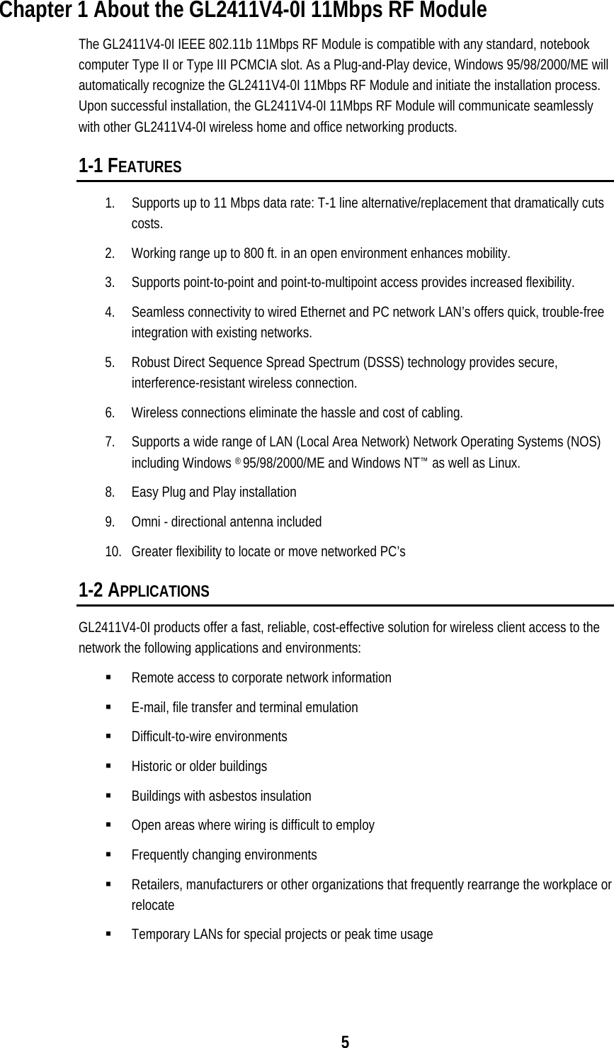
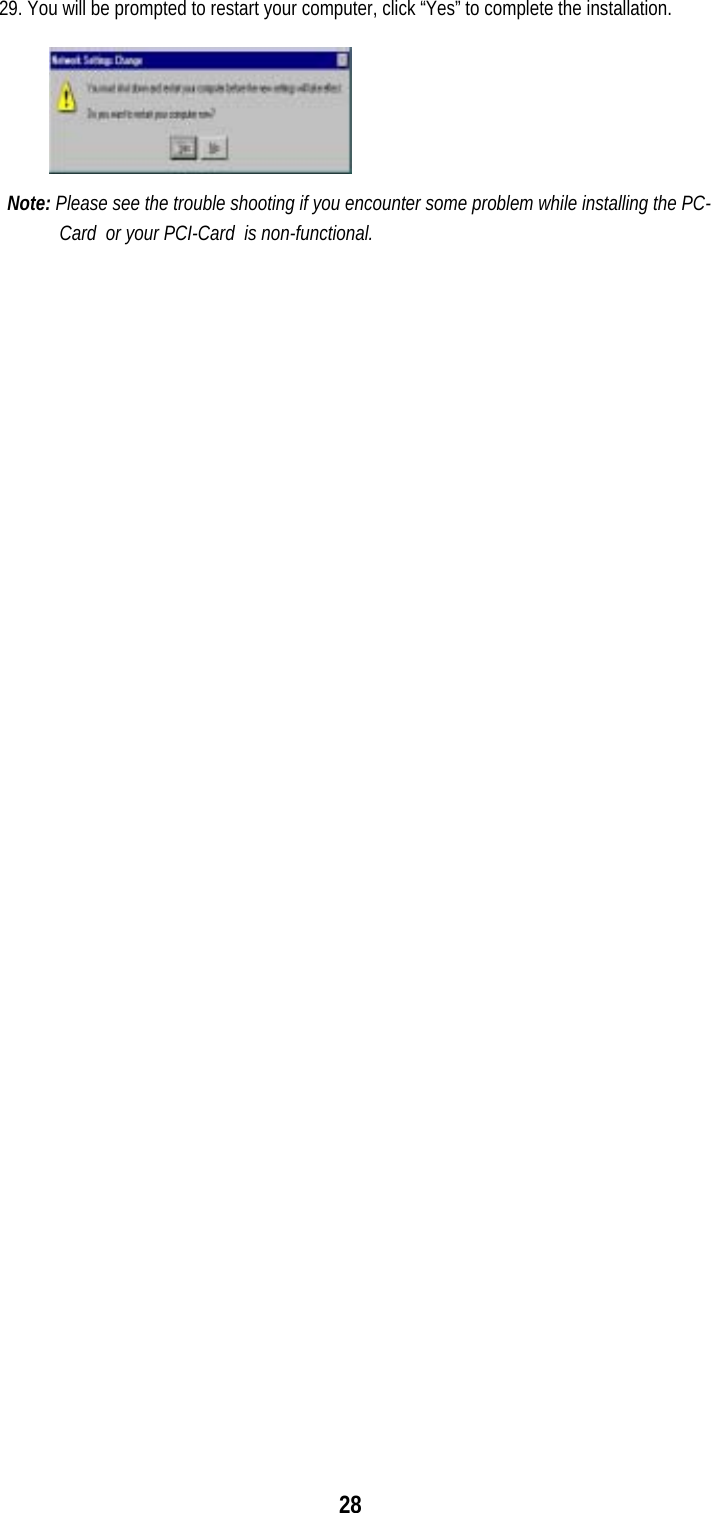
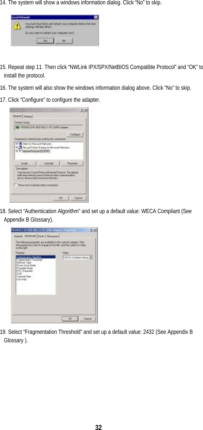
![52 dot11DesiredSSID="linux-wlan" ; Download code/data? ; If you want to configure the card for station,set WLAN_DOWNLOAD to 'n'. WLAN_DOWNLOAD=n WLAN_DOWNLOADER=/sbin/prism2dl WLAN_DLIMAGE=/etc/pcmcia/APFW.hex ; Do we want to be an AP? Set IS_AP to 'n' because it will not work. IS_AP=n # y|n 12) Edit your network.opts file to set up your IP settings. # vi /etc/pcmcia/network.opts ;Transceiver selection, for some cards -- see 'man ifport' IF_PORT="" ; Use BOOTP? [y/n] BOOTP="n" ; Use DHCP? [y/n] ; If your local network has DHCP, you can set DHCP to 'y' then save the ; file and exit.If you set DHCP to 'n', you must set the items below. DHCP="n" ; Host's IP address, netmask, network address, broadcast address ; It is a example to set the items for my local network. You must depend ; on your system. IPADDR="192.168.0.201" NETMASK="255.255.255.0" NETWORK="192.168.0.0" BROADCAST="192.168.0.255" ; Gateway address for static routing GATEWAY="192.168.0.1" ; Things to add to /etc/resolv.conf for this interface DOMAIN="lcat" SEARCH=" DNS_1="140.118.7.125" DNS_2="" DNS_3="" ; You can save the file and exit now if you don't care the other options.](https://usermanual.wiki/Global-Sun-Technology/GL2411V4-0I/User-Guide-238365-Page-52.png)