Global Sun Technology GL242201 PCMCIA Wireless LAN Card User Manual PC Card MANUAL 22OEM
Global Sun Technology Inc PCMCIA Wireless LAN Card PC Card MANUAL 22OEM
UserManual.wiki
>
Global Sun Technology
>
GL242201 User Manual
Manual
Navigation menu
Upload a User Manual
Namespaces
Wiki Guide
HTML
PDF
Info
Views
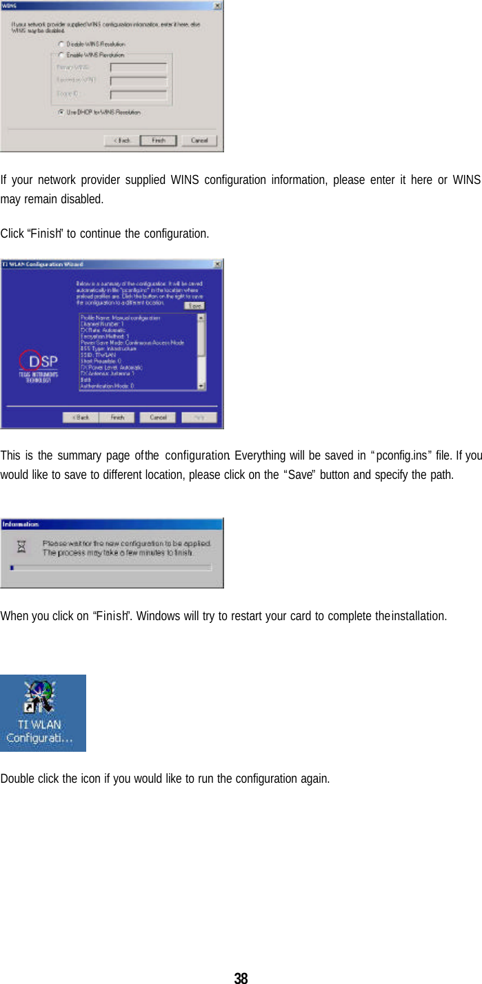
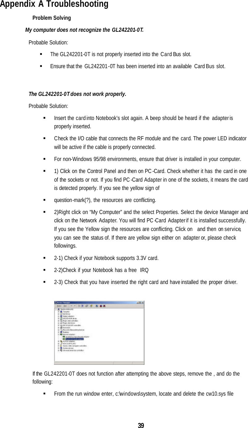
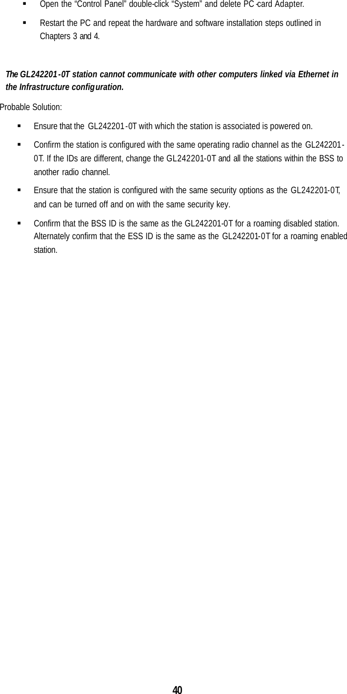
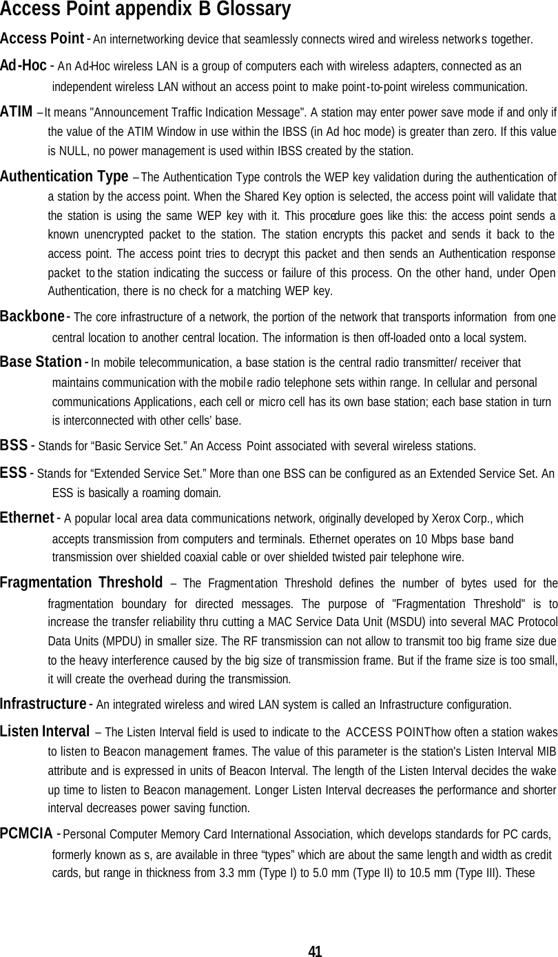
User Manual
Discussion / Help
Navigation