Global Sun Technology GL2554MP-1A 2.4/5GHz 54Mbps Wireless LAN Mini-PCI Card User Manual Manual Rev 2
Global Sun Technology Inc 2.4/5GHz 54Mbps Wireless LAN Mini-PCI Card Manual Rev 2
Manual Rev 2

54Mbps Wireless Network
Mini PCI Adapter
USER’S MANUAL
Model Name: GL2554MP-1A
Version: 1.0
Date: 15/10/03
Please make sure TURN OFF your computer and remove the power cord from your
PC. Open the computer case and then please insert the 54Mbps Wireless mini PCI
Adapter. Once the 54Mbps Wireless mini PCI Adapter is installed, place the
computer case back. Turn ON your computer.
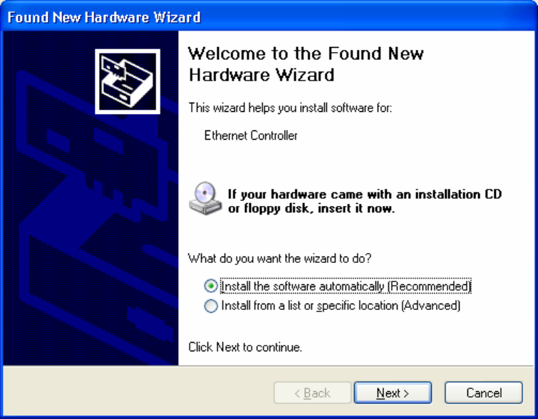
Driver Installation
1. Please select the second option and click “Next”.
2. Please click “Continue Anyway”
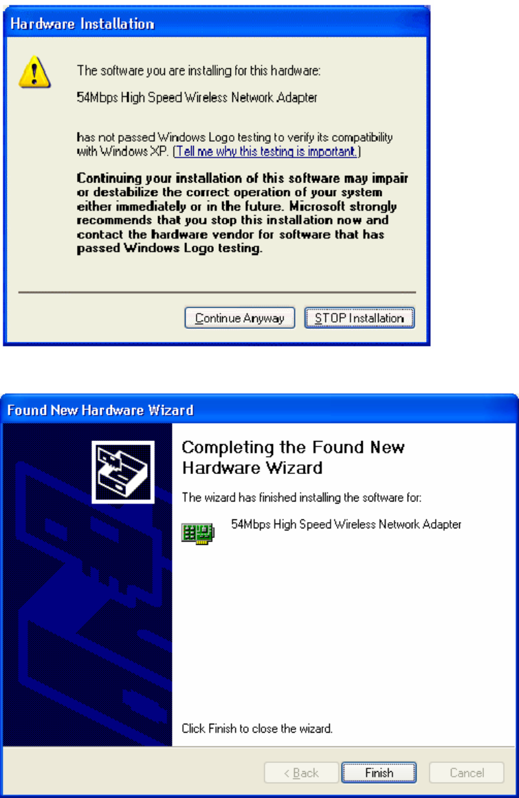
3. Please click “Finish”
4. To make sure if the installation is successful, you could check it through the
device management.
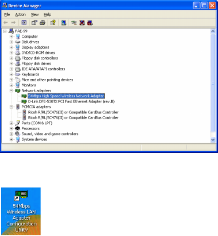
5. Once the installation is successful, a utility program icon will show on your
desktop. To lunch the utility, just double click the icon.
Federal Communication Commission Interference Statement
This equipment has been tested and found to comply with the limits for
a Class B digital device, pursuant to Part 15 of the FCC Rules. These
limits are designed to provide reasonable protection against harmful
interference in a residential installation. This equipment generates,
uses and can radiate radio frequency energy and, if not installed and
used in accordance with the instructions, may cause harmful
interference to radio communications. However, there is no guarantee
that interference will not occur in a particular installation. If this
equipment does cause harmful interference to radio or television
reception, which can be determined by turning the equipment off and
on, the user is encouraged to try to correct the interference by one of
the following measures:
- Reorient or relocate the receiving antenna.
- Increase the separation between the equipment and receiver.
- Connect the equipment into an outlet on a circuit different from that
to which the receiver is connected.
- Consult the dealer or an experienced radio/TV technician for help.
This device complies with Part 15 of the FCC Rules. Operation is
subject to the following two conditions: (1) This device may not cause
harmful interference, and (2) this device must accept any interference
received, including interference that may cause undesired operation.
FCC Caution: Any changes or modifications not expressly approved by
the party responsible for compliance could void the user's authority to
operate this equipment.
IMPORTANT NOTE:
FCC Radiation Exposure Statement:
This equipment complies with FCC radiation exposure limits set forth for an
uncontrolled environment. This equipment should be installed and operated
with minimum distance 20cm between the radiator & your body.

This device is intended only for OEM integrators under the following
conditions:
1) The antenna must be installed such that 20 cm is maintained between the
antenna and users, and
2) The antenna should be integral if the end device is intended to be operated
in 5.15 ~ 5.25GHz frequency range.
As long as 2 conditions above are met, further transmitter test will not be
required. However, the OEM integrator is still responsible for testing their
end-product for any additional compliance requirements required with this
module installed (for example: Notebook, Wirelesss Access Point ,Wireless
Router, etc.).
IMPORTANT NOTE: In the event that these conditions can not be met (for
example certain laptop configurations or co-location with another transmitter),
then the FCC authorization is no longer considered valid and the FCC ID can
not be used on the final product. In these circumstances, the OEM integrator
will be responsible for re-evaluating the end product (including the transmitter)
and obtaining a separate FCC authorization.
End Product Labeling
This transmitter module is authorized only for use in device where the
antenna may be installed such that 20 cm may be maintained between the
antenna and users. The final end product must be labeled in a visible area
with the following: “Contains TX FCC ID:O7J-GL2554MP-1A ”.
Manual Information That Must be Included
The OEM integrator has to be aware not to provide information to the end
user regarding how to install or remove this RF module in the users manual of
the end product which integrate this module.
The users manual for OEM integrators end users must include the following
information in a prominent location “ IMPORTANT NOTE: To comply with FCC
RF exposure compliance requirements, the antenna used for this transmitter
must be installed to provide a separation distance of at least 20 cm from all
persons and must not be co-located or operating in conjunction with any other
antenna or transmitter”.
If the end product integrating this module is going to be operated in 5.15 ~
5.25GHz frequency range, the warning statement in the user manual of the
end product should include the restriction of operating this device in indoor
could void the user’s authority to operate the equipment.

Global Sun Technology Inc.
Installation Manual for Mini PCI Card
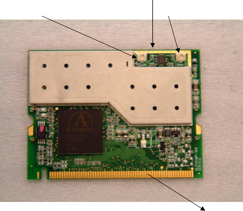
Step 1 Take the Mini PCI card top
connector for aux antenna connector for Main antenna
bottom
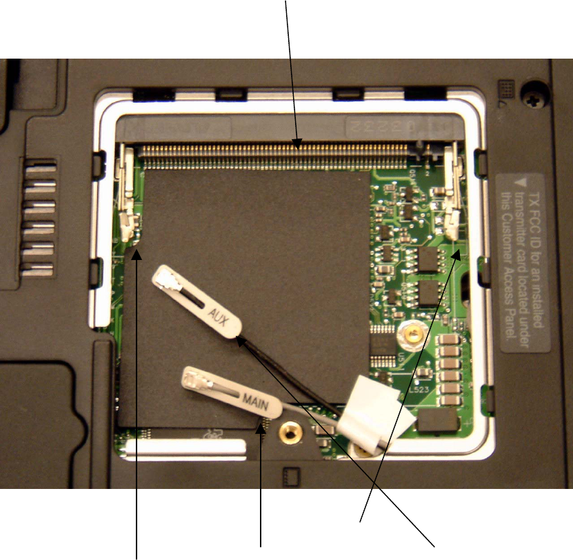
Card Slot
connecting with the bottom of the Mini PCI Card
Right clip
Left Clip Main Antennae Aux Antennae
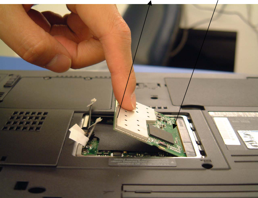
Step 2
Insert the Mini PCI card into the card slot with downside toward the slot
Top side bottom side
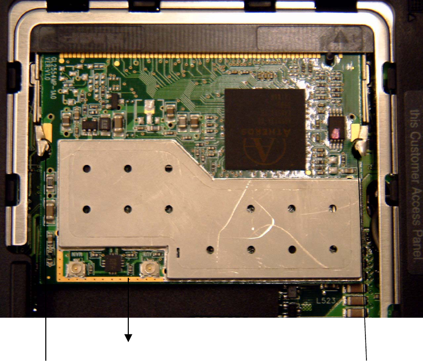
Step 3
Press down the top upperside of the card doward. A click sound made by the clippers
on both left and right side of the slot signals that the card is firmly inserted to its
position
top side
Left Clip Right Clip
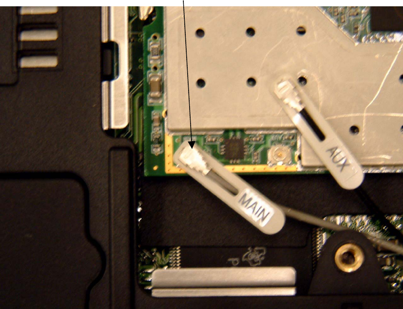
Step 4.
Connecting the main antenna to the main connector.
Connector for the main antenna
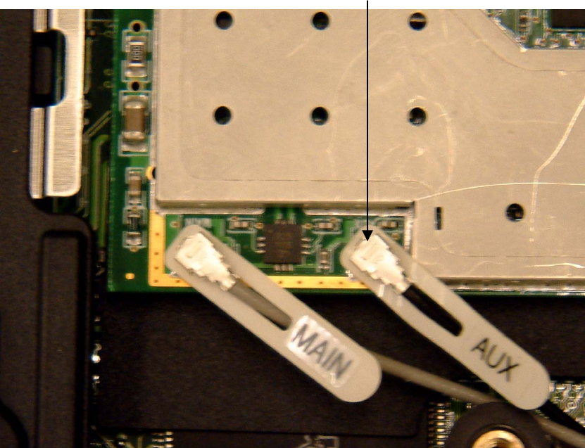
Step 5
Connecting aux antennae to the aux connector. When both antennae are connected to
the connectors as the picture shown below, the Mini PCI Card installation is
completed.
Aux connector
Notification on Antennae
Please be notice that the antennae must be firmly located inside the TFT-LCD panel.
According to FCC regulation, to ensure the antenna will be kept at 20 cm away from
users, the tip of the antennae must be firmly installed inside the top part of the
TFT-LCD panel !