Global Traffic Technologies OPTICOMGPS1 Opticom GPS User Manual
Global Traffic Technologies, LLC Opticom GPS
User Manual

Opticom GPS System
Vehicle Equipment
Installation Manual June
2011

Vehicle Equipment Installation Instructions i
Table of Contents
1About This Manual ......................................................................................................................................... 1
1.1Purpose of Manual ................................................................................................................................... 1
1.2Manual Conventions ................................................................................................................................ 1
1.3Related Publications ................................................................................................................................ 1
1.4Manual Organization ............................................................................................................................... 1
2Safety Information .......................................................................................................................................... 2
2.1Intended Use ............................................................................................................................................ 2
2.2Technical Support .................................................................................................................................... 2
2.3Safety Messages and Safety Labels ..................................................................................................... 2
2.3.1Safety Message Format .................................................................................................................. 2
2.3.2Safety Label Format ........................................................................................................................ 3
2.4Safety Messages Contained in this Manual ......................................................................................... 4
2.5Label Locations ........................................................................................................................................ 6
2.6Safety Considerations ............................................................................................................................. 7
2.6.1Personal Safety Equipment and Clothing .................................................................................... 7
2.6.2Electric Shock ................................................................................................................................... 7
2.6.3Explosion ........................................................................................................................................... 7
2.6.4Chemical Burns ................................................................................................................................ 7
2.7Disposal of Device ................................................................................................................................... 7
2.8FCC Statement ......................................................................................................................................... 7
3Description ....................................................................................................................................................... 8
3.1Opticom™ GPS System ......................................................................................................................... 8
3.2Vehicle Equipment ................................................................................................................................... 9
3.3Parts List .................................................................................................................................................. 10
4Features .......................................................................................................................................................... 10
5Installation ...................................................................................................................................................... 11
5.1Vehicle Radio/GPS Unit Installation .................................................................................................... 12
5.2Model 1050 Radio/GPS antenna installation ..................................................................................... 13
5.3Model 794HM, Model 794TM ............................................................................................................... 14
5.4Radio/GPS Unit Cable Terminations .................................................................................................. 15
5.5Vehicle Control Unit Installation ........................................................................................................... 16
5.5.1Turn Signal Sensing Connections ............................................................................................... 20
5.5.2Additional Vehicle Connections ................................................................................................... 20
5.5.3Low Priority ..................................................................................................................................... 21
5.5.4Probe Priority/GPS always out ..................................................................................................... 21
6Checkout ......................................................................................................................................................... 22
6.1Configuration Setup and Checkout ..................................................................................................... 22
6.2Input Verification .................................................................................................................................... 22
6.3Performance Tests ................................................................................................................................ 23
7Troubleshooting ........................................................................................................................................... 25
8Maintenance ................................................................................................................................................... 27
9GPS Output Function .................................................................................................................................. 26

Vehicle Equipment Installation Instructions 1
1 About This Manual
1.1 Purpose of Manual
This manual provides step-by-step instructions
for installing the Global Traffic Technologies
Opticom™ GPS System* vehicle equipment. It
is intended for use by installers, maintenance
personnel, and others who are responsible for
the installation and maintenance of the system.
1.2 Manual Conventions
The conventions listed in Table 1-1 help to
make this manual easier to use by presenting
a uniform approach to the descriptions,
phrases, and nomenclature.
1.3 Related Publications
Opticom™ GPS System Intersection
Equipment Installation Instructions.
Opticom™ GPS System Operation Manual.
1.4 Manual Organization
This manual is divided into eight sections.
Section 1. About This Manual
Contains information about the organization and
content of this manual.
Section 2. Safety Information
Contains important information about the safety
messages, safety labels, safety precautions, and
procedures for installation of this device.
Section 3. Description
Briefly describes the vehicle equipment and
related system components.
Section 4. Features
Describes important features and
characteristics of the vehicle equipment.
Section 5. Installation
Contains step-by-step installation instructions.
Section 6. Checkout
Contains information on how to check out
and test the installed system.
Section 7. Troubleshooting
Contains problem solutions to troubleshoot
the installed system.
Section 8. Maintenance
Contains information and recommendations to
ensure reliable system operation.
Table 1-1. Manual Conventions
Element Convention Example
Names First or formal reference: initial
caps Opticom™ GPS System Vehicle
Radio/GPS Unit
Subsequent use or informal
reference: lowercase radio/GPS unit
Feature names Initial caps the Disable feature
Switch position Uppercase the OFF position
*The method of using the components of the Opticom GPS system may be covered by one or more of
US Patent Numbers 5539398, 5926113, 5986575, 6243026.
Vehicle Equipment Installation Instructions 2
2 Safety Information
We provide important safety information and
warnings to assist you in understanding and
avoiding potential harm to yourself, and
possible damage to equipment, during the
installation of Opticom™ GPS System
equipment. Although we have included
many potential hazards you may encounter
during the installation of this equipment, we
cannot predict all of the possible hazards
and this list should not be a substitute for
your judgment and experience.
Please read, understand, and follow all
safety information contained in these
instructions before installing the system
equipment. Save this installation manual
and keep it near the equipment.
If you are unsure about any part of this
installation or of the potential hazards
discussed, please contact your supervisor
immediately.
2.1 Intended Use
The system is intended to assist authorized
priority vehicles through signalized intersections
by providing temporary right-of-way through
vehicle operator interface to the system and
through the use of common traffic controller
functions. GTT has not evaluated this product for
use in any other application.
2.2 Technical Support
If you have questions about the system, its
use, or operation, please contact your dealer
or call the GTT Technical Service department
at 1-800-258-4610.
2.3 Safety Messages and Safety Labels
We include safety messages and safety
labels in this manual to help you protect your
safety and the safety of others. This section
contains important information to help you
recognize and understand these safety
messages.
Please read all messages before proceeding
with the installation.
2.3.1 Safety Message Format
Safety messages are designed to alert you to
potential hazards that can cause personal injury
to you or others. They can also indicate the
possibility of property damage.
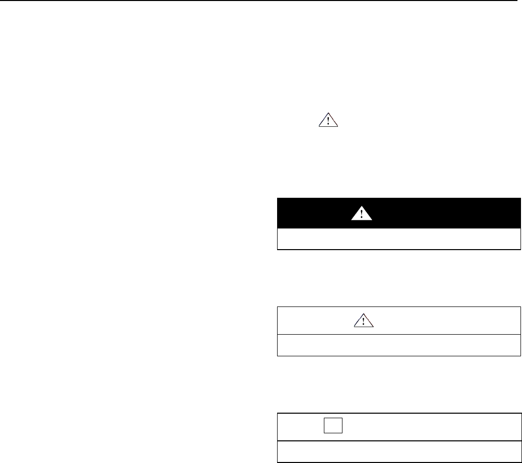
Each safety message box contains a safety alert
symbol ( ); one of three signal words:
WARNING, CAUTION, or IMPORTANT NOTE;
and a safety message.
The signal words and symbols, and their
meanings, are shown below:
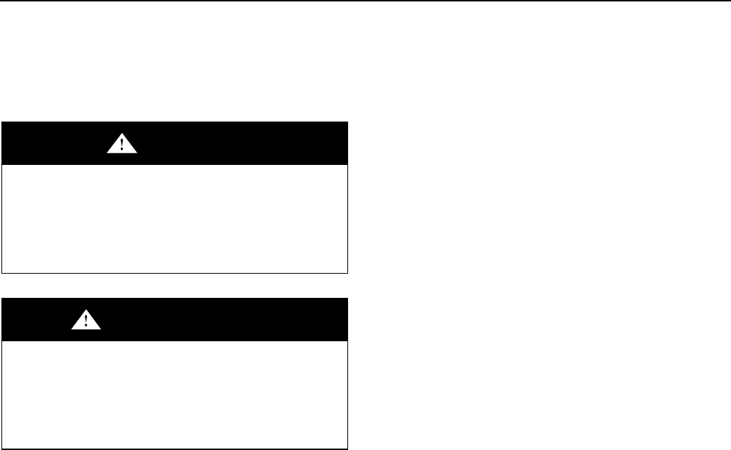
WARNING
The safety message is in this box.
WARNING indicates a potentially hazardous
situation, which, if not avoided, could result
in death or serious injury.
CAUTION
The safety message is in this box.
CAUTION indicates a potentially hazardous
situation, which, if not avoided, may result in
minor or moderate injury.
IMPORTANT NOTE
The safety message is in this box.
IMPORTANT NOTE indicates a potentially
hazardous situation, which, if not avoided,
may result in property damage.
In addition to the symbols and words explained
above, each safety message identifies the
hazard, describes what you can and should do
to avoid the risk of exposure to the hazard, and
tells the probable consequences of not avoiding
the hazard.
Vehicle Equipment Installation Instructions 3
2.3.2 Safety Label Format
We include safety labels on the devices to help
you protect your safety and the safety of others.
Safety labels are designed to alert you to
potential hazards associated with a piece of
equipment that can cause personal injury to you
or others. They can also indicate the possibility
of property damage.
Please read all safety labels.
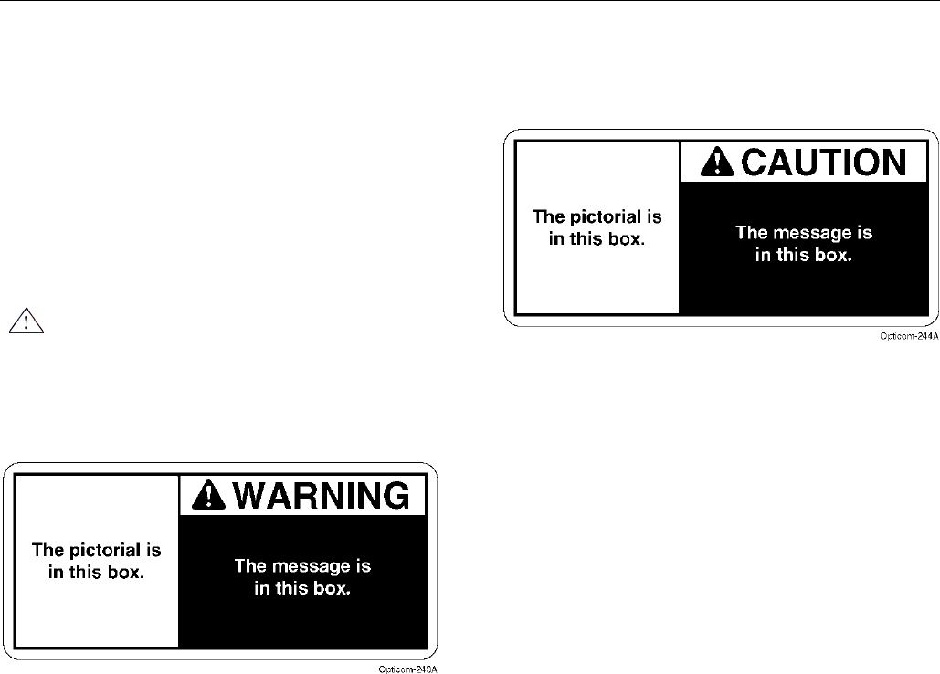
Each safety label contains a safety alert symbol
(), one of two signal words: WARNING or
CAUTION, a pictorial showing the nature of the
hazard, and a safety message.
The signal words and symbols, and their
meanings, are shown below:
WARNING indicates a potentially hazardous
situation, which, if not avoided, could result
in death or serious injury.
CAUTION indicates a potentially hazardous
situation, which, if not avoided, may result in
minor or moderate injury.
We consider safety labels to be an important
part of all devices and they should be replaced
immediately if they become hard to read.
If any of the safety labels are missing or cannot
be read, please contact your dealer or the GTT
Repair department for a replacement.
Vehicle Equipment Installation Instructions 4
2.4 Safety Messages Contained in this
Manual
The following safety messages appear in this
manual:
WARNING
This equipment has been approved for mobile
applications where the equipment should be
used at distances greater than 20 cm from the
human body (with the exception of hands,
wrists, feet and ankles). Operation at distances
less than 20cm is strictly prohibited.
AVERTISSEMENT
Cet équipement a été approuvé pour les applications
mobiles où l'équipement devrait être utilisé aux
distances plus grandes que 20 cm du corps humain
(avec l'exception de mains, les poignets, les pieds et
les chevilles). L'opération aux distances moins que
20 cm est strictement interdit.
Note: This equipment has been tested and
found to comply with the limits for a Class
A digital device, pursuant to part 15 of the
FCC Rules. These limits are designed to
provide reasonable protection against
harmful interference when the equipment is
operated in a commercial environment.
This equipment generates, uses, and can
radiate radio frequency energy and, if not
installed and used in accordance with the
instruction manual, may cause harmful
interference to radio communications.
Operation of this equipment in a residential
area is likely to cause harmful interference
in which case the user will be required to
correct the interference at his own
expense.
Note: Cet équipement a été testé et trouvé
conforme aux limites pour un numérique de
classe A, conformément à la partie 15 des
règles FCC. Ces limites sont conçues pour
fournir une protection raisonnable contre les
interférences nuisibles lorsque l'équipement
est utilisé dans un environnement
commercial. Cet équipement génère, utilise
et peut émettre des fréquences radio et, s'il
n'est pas installé et utilisé conformément aux
instructions, peut causer des interférences
nuisibles aux communications radio.
L'opération de cet équipement dans une
zone résidentielle est susceptible de
provoquer des interférences nuisibles,
auquel cas l'utilisateur devra corriger ces
interférences à ses propres frais.
NOTICE
This Class A digital apparatus complies with
Canadian ICES-003.
Cet appareil numérique de la classe A
conforme à la norme NMB-003 du Canada.
Vehicle Equipment Installation Instructions 5
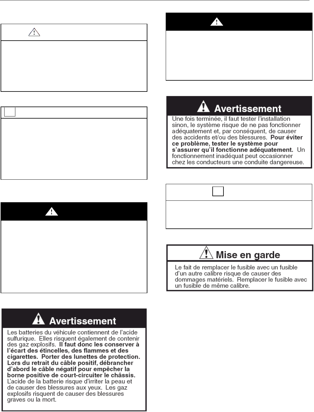
IMPORTANT NOTE
Modifying the radio/GPS unit may seriously
damage the equipment and void the warranty.
Do not attempt to modify the radio/GPS
circuitry in any way. Modifying the radio
and/or antenna in any way may cause the radio
to violate FCC/IC requirements.
REMARQUE IMPORTANTE
La modification du système radio/GPS risque
d’endommager sérieusement le matériel et
d’annuler la garantie. Ne pas tenter de
modifier les circuits du système radio/GPS
de quelque façon que ce soit. En modifiant le
système radio et/ou l’antenne de quelque façon
que ce soit, la radio risque de ne plus répondre
aux exigences de la FCC/IC.
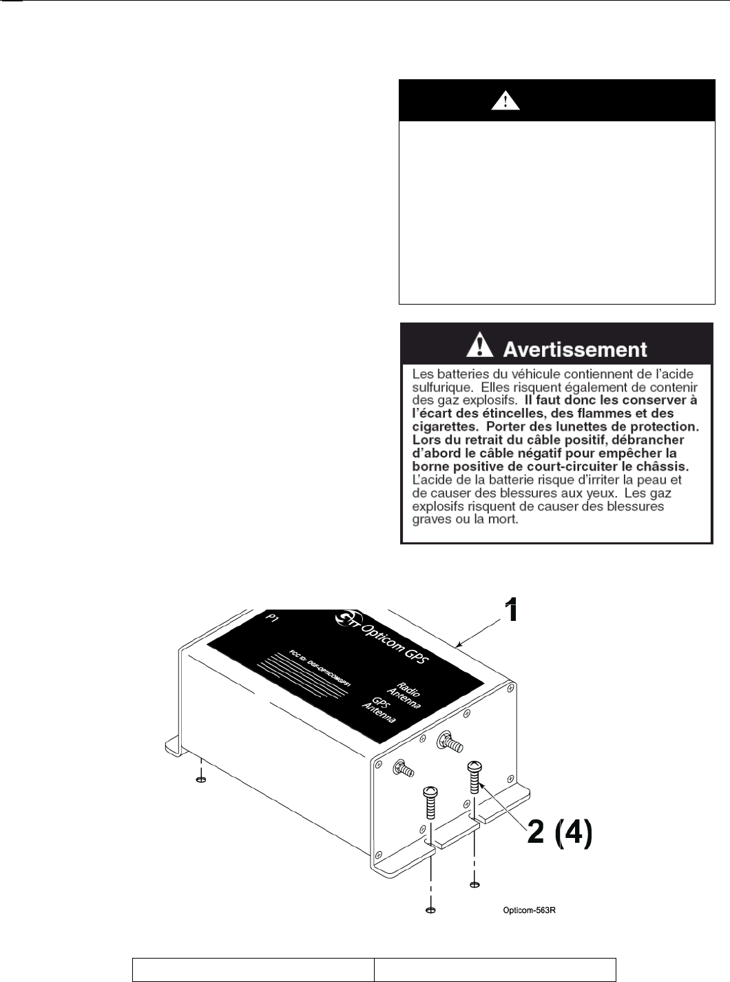
WARNING
Vehicle batteries contain sulfuric acid and
may contain explosive gases. Keep sparks,
flames, and cigarettes away. Wear eye
protection. Disconnect the negative
cable first to prevent shorting the positive
terminal to the chassis when removing
the positive cable. Battery acid may cause
skin irritation and eye injury. Explosive
gases may cause severe injury or death.
WARNING
A completed installation that is not tested may
result in improper system operation, which may
result in accidents and/or injuries. To avoid
this problem, test the system to verify
proper operation. Improper system operation
may result in unsafe driver action.
CAUTION
Failure to replace the fuse size as marked may
cause property damage. Replace fuse size as
marked.
Vehicle Equipment Installation Instructions 6
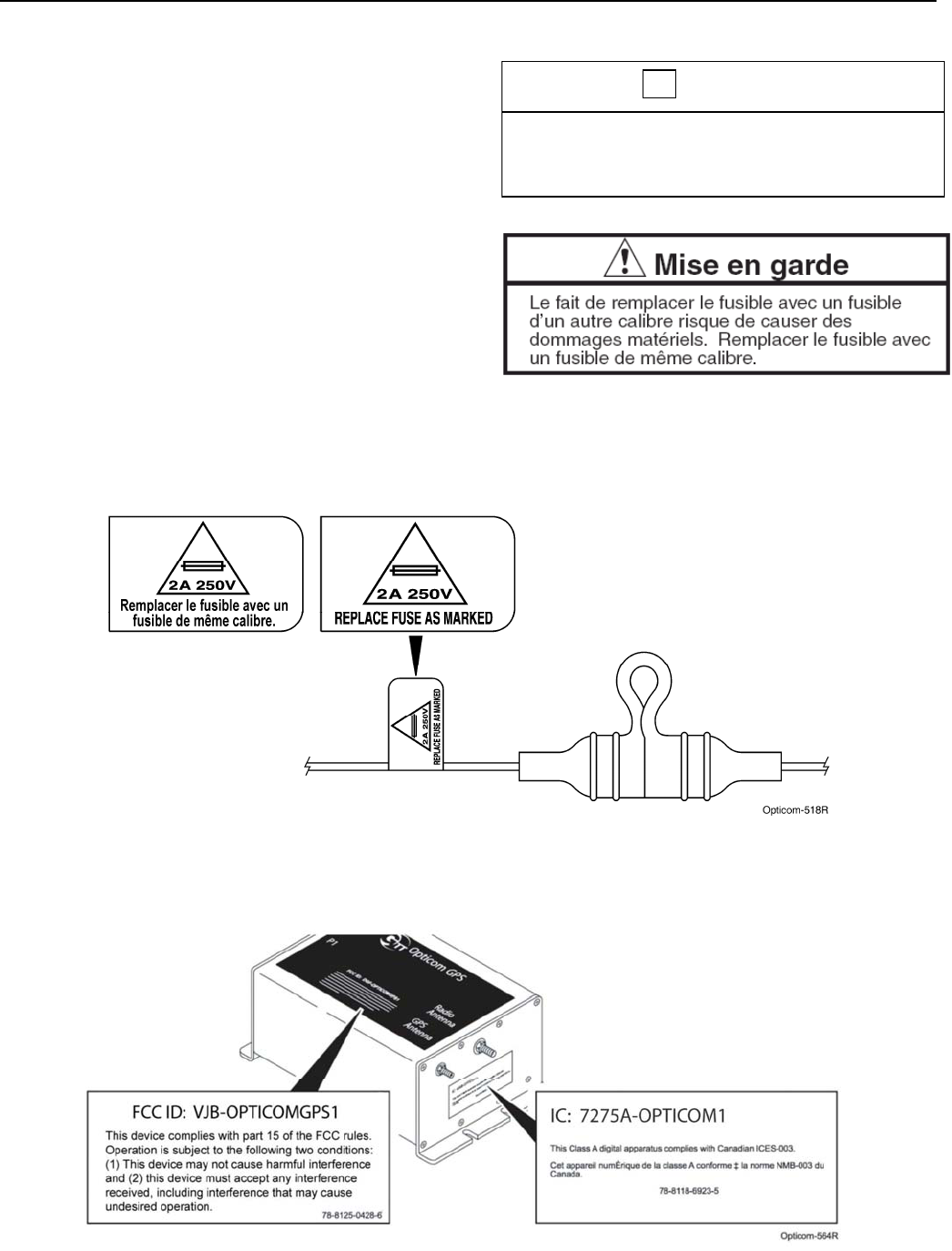
2.5 Label Locations
There is one safety label, one FCC label and
one IC label on the Opticom™ GPS System
vehicle equipment. If a label is missing or
cannot be read, please contact your dealer or
the GTT Repair department for a
replacement. See Figures 2-1 and 2-2 for
label locations.
Il ya une étiquette de sécurité, une étiquette de
la FCC et une étiquette IC sur l'équipement
Opticom ™ GPS Système de véhicule. Si une
étiquette est manquante ou ne peut pas être lue,
s'il vous plaît contacter votre revendeur ou le
département de service de GTT pour un
remplacement. Voir les figures 2-1 et 2-2 pour
les emplacements des étiquettes.
CAUTION
Failure to replace the fuse size as marked may
cause property damage. Replace fuse size as
marked.
Figure 2-1. Vehicle Equipment Fuse Safety Label Location
Figure 2-2. FCC, IC Label Location

Vehicle Equipment Installation Instructions 7
2.6 Safety Considerations
Please consider the following safety issues
before beginning the installation of the
Opticom™ GPS System vehicle equipment.
Although we have compiled this list of common
safety considerations, it should not be
considered as complete. It is not intended to
take the place of your good judgment, training,
and experience.
2.6.1 Personal Safety Equipment and
Clothing
Personal safety equipment and clothing
including high visibility vests, hard hats, gloves,
electrical shock or electrocution protection
clothing and equipment, safety shoes, safety
glasses, face shields, goggles, and hearing
protection devices are just some of the items
available to you.
Choose the right equipment for the job. If you
are unsure of which safety equipment is
recommended or appropriate for the job, ask
your supervisor or foreman.
2.6.2 Electric Shock
As a trained installer of electrical equipment you
are aware of the dangers associated with
installation of electrical devices. Always be sure
that the power to the equipment, and all
associated equipment, is turned off and the
vehicle battery is disconnected. Use the
equipment, techniques, and procedures that you
learned during your training or apprenticeship or
other electrical industry recognized safety
procedures.
If you are unsure of which techniques,
procedures, and protective equipment are
recommended or appropriate for the job, ask
your supervisor or foreman.
2.6.3 Explosion
Common automotive-type batteries produce an
explosive gas under some conditions. This
gas may easily be ignited by a spark or flame
as you work on the vehicle. To reduce the risk
of explosion, disconnect the battery, work in a
well ventilated area, avoid the use of devices
that create sparks or use open flames, and use
the appropriate personal safety equipment and
clothing.
If you are unsure of which techniques,
procedures, and protective equipment are
recommended or appropriate for the job, ask
your supervisor or foreman.
2.6.4 Chemical Burns
Common automotive-type batteries contain
strong acid that can cause personal injury if you
come in contact with the acid. To reduce
exposure to the risk of chemical burns, wear
appropriate protective clothing and handle the
battery with care.
If you are unsure of which techniques,
procedures, and protective equipment are
recommended or appropriate for the job, ask
your supervisor or foreman.
2.7 Disposal of Device
Please dispose of the device in accordance
with all local, state, and federal laws and
regulations.
2.8 FCC Statement
This equipment has been tested and found to
comply within the limits for a Class A digital
device, pursuant to part 15 of the FCC rules.
These limits are designed to provide
reasonable protection against harmful
interferences when the equipment is operated
in a commercial environment. This equipment
generates uses and can radiate radio
frequency energy and, if not installed and used
in accordance with the instruction manual, may
cause harmful interference to radio
communications. If operation of this
equipment in a residential area causes harmful
interference, the user is required to correct the
interference at their own expense. See Figure
2-2.

Vehicle Equipment Installation Instructions 8
3 Description
This section provides a general description of
the Opticom™ GPS system and a detailed
description of the vehicle equipment.
3.1 Opticom™ GPS System
The Opticom GPS system assists authorized
priority vehicles through signalized
intersections by providing temporary right-of-
way through the use of common traffic
controller functions.
The Opticom GPS system consists of the
following matched components:
Vehicle Equipment —
Radio/GPS unit containing a GPS receiver
and a 2.4 GHz transceiver
Radio/GPS antenna
Control unit
Intersection Equipment —
Radio/GPS unit containing a GPS receiver
with antenna and a 2.4 GHz transceiver with
antenna
Or Radio/GPS unit containing a GPS
receiver and a 2.4 GHz spread spectrum
transceiver with a separate Radio/GPS
antenna
Phase Selector
Card Rack/Input File
Auxiliary Interface Panel
Auxiliary Harness
The vehicle equipment is mounted on the priority
vehicle. Its GPS receiver acquires position
information from the constellation of GPS
satellites. This information is used to compute
the location, speed, and heading of the vehicle.
This information, along with a priority request and
the state of the vehicle’s turn signal, is broadcast
using the 2.4 GHz transceiver.
The intersection equipment receives the radio
transmission from the vehicle equipment. The
intersection equipment then compares the
information being received from the vehicle to
the parameters stored in the intersection
equipment’s memory. If the vehicle is heading
toward the intersection in a predefined
approach corridor, is requesting preemption
and has met all other programmed
parameters, the corresponding phase selector
output is activated. This output is connected to
the traffic controller preemption input. When
activated, the controller cycles to grant a green
light to the requesting vehicle or holds the
green allowing the vehicle to pass through the
intersection.
The card rack/input file provides the power and
logic wiring for the phase selector, which plugs
directly into a slot in the unit.
The auxiliary interface panel provides additional
connections for monitoring green phases and
also provides additional priority control outputs.
The green sense harness can be used to
provide additional connections for monitoring
green phases when the auxiliary interface panel
is not required.
Vehicle Equipment Installation Instructions 9
3.2 Vehicle Equipment
The Opticom™ GPS System vehicle equipment
is intended for use on priority vehicles. The
vehicle equipment consists of a radio/GPS unit
containing a GPS receiver and a 2.4 GHz
transceiver, a radio/GPS antenna, as well as a
control unit, which also provides an interface
point between the radio/GPS unit, the vehicle
wiring, and an external PC used for
configuration and diagnostics.
This manual describes how to install the vehicle
equipment.
Please be aware of the following operational
characteristics of this equipment.
Appropriate agency ID, vehicle class, and
vehicle ID numbers are determined at the time
of installation and are programmed by the user
via configuration software.
The Disable feature uses an additional switch
(customer supplied) that connects to battery
negative or positive when actuated.
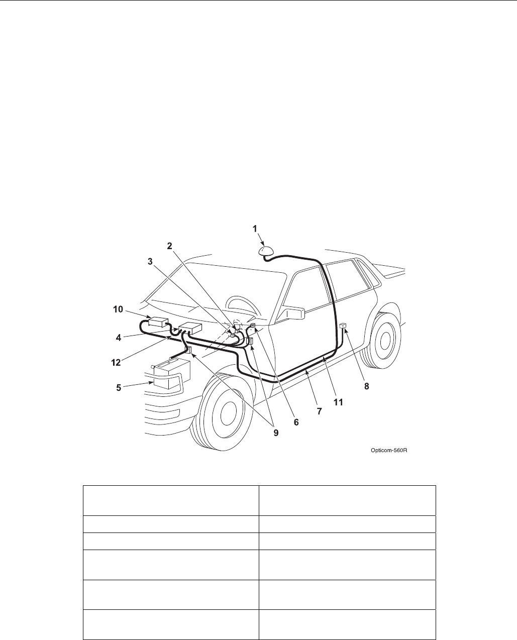
Figure 3-1 shows a typical vehicle equipment
installation for a priority vehicle.
Figure 3-1. Typical Vehicle Equipment Installation for Priority Vehicle
1. Radio/GPS antenna (Model
1050) 7. Radio/GPS antenna cable
2. Left turn signal sense 8. Disable switch
3. Right turn signal sense 9. Fuses
4. Model 1020-1021 Vehicle
control unit (VCU) 10. Model 1012 Radio/GPS unit
5. Battery 11. Vehicle interface harness
(Model 1071)
6. Light bar sense 12. Control Unit cable assembly
(Model 1072)

Vehicle Equipment Installation Instructions
10
3.3 Parts List
The following is a list of components in the vehicle
kit. See Figure 3-1 for more details.
1 Model 1050 Radio/GPS antenna
White 3” diameter dome with two 15’
cables.
4 Model 1020 or 1021 Vehicle Control Unit (VCU
Black module with ON/OFF switch and
indicators
Mounting bracket and screws.
10 Model 1012 Radio/GPS unit
Aluminum module with mounting
screws
11 Model 1071 Vehicle Interface Harness
15’ Cable with a DB-15 connector and
15’ of un-terminated loose wires
12 Model 1072 control unit cable assembly
20’ Cable with a DB-15 connector
and a black cable
Miscellaneous parts
Two fuse holders
Two 2 amp fuses
Two fuse labels
Two Grommets
Installation Instructions
4 Features
Opticom™ GPS system vehicle equipment has
the following features:
Vehicle identification encoding; selectable at
installation
User-selectable Disable mode; Latching
or Non-Latching modes
Diagnostic indicators
Millions of vehicle identification codes
Agency ID capability
Wide operational temperature range:
–30°F to +165°F (–34°C to +74°C)
Meets FCC part 15 Class A specifications
Additional GPS output in NMEA format for
other onboard uses
R5485/J1708 serial interfaces
15 & 20-foot cables for installation flexibility
Available Windows™* Configuration and
Maintenance Software
* Windows is a trademark of Microsoft Corporation.
Vehicle Equipment Installation Instructions 11
5 Installation
This section describes the installation of the
Opticom™ GPS System vehicle equipment.
Please read and fully understand the following
paragraphs before starting the installation.
Before cutting or drilling any openings in the
vehicle or lightbar, draw a diagram showing
placement, measurements, and dimensions.
Use the diagram to avoid drilling or cutting
holes in undesirable locations.
Always follow the vehicle manufacturer's
recommendations for modification,
alteration, and installation or connection of
accessories or equipment to the vehicle
and lightbar.
Installation on specialty vehicles (such as
motorcycles, parking enforcement, utility
and special maintenance vehicles)
requires particular care and attention to
details.
Do not mount the radio/GPS antenna within
18 inches of any other radio antenna.
Follow the installation instructions to avoid
possible radio frequency interference
problems.
The radio/GPS unit is not watertight;
therefore it should be mounted inside the
passenger compartment or some other
protected area of the vehicle.
Never operate the equipment with the
antenna cables disconnected or the
equipment may be damaged.
The radio/GPS antenna should be mounted
level and as high on the vehicle as possible.
The radio/GPS antenna should have an
unobstructed view of at least 50% of the sky.
The radio/GPS antenna must not be
obstructed by light bars, speakers,
antennas, or other devices especially
towards the front of the vehicle.
Wires that are routed under carpets or mats
should be run between the pad and the
carpet. This will minimize abrasion and heat
damage from catalytic converters.
Protect cables with armor or sheathing when
they are routed around sharp corners and
edges. Avoid routing cables through
potential pinch points. Clamp or tie all cables
in place. Route and secure cables well away
from moving parts.
Do not paint the radio/GPS antenna cover.
Metals or metal oxides in the paint may
interfere with GPS reception and/or radio
reception and transmission.
Do not modify the radio/GPS unit circuitry.
There are no user serviceable parts inside.
IMPORTANT NOTE
Modifying the radio/GPS unit may seriously
damage the equipment and void the warranty.
Do not attempt to modify the radio/GPS
circuitry in any way. Modifying the radio
and/or antenna in any way may cause the radio
to violate FCC/IC requirements.
REMARQUE IMPORTANTE
La modification du système radio/GPS risque
d’endommager sérieusement le matériel et
d’annuler la garantie. Ne pas tenter de modifier
les circuits du système radio/GPS de quelque
façon que ce soit. En modifiant le système radio
et/ou l’antenne de quelque façon que ce soit, la
radio risque de ne plus répondre aux exigences de
la FCC/IC.
Vehicle Equipment Installation Instructions
12
5.1 Vehicle Radio/GPS Unit Installation
This subsection describes how to install the
vehicle radio/GPS unit.
1. Disconnect the battery before beginning the
installation. Disconnect the negative battery
cable first, then the positive battery cable.
2. Remove interior panels and headliners, as
necessary, to provide access for cable
routing.
3. Determine an appropriate location in a
protected area inside of the vehicle or trunk.
4. Using the provided screws, attach the
Radio/GPS unit to the mounting location.
5. The provided screws are self drilling/tapping
screws.
Note: The radio/GPS unit is not watertight;
therefore it should be mounted inside the
passenger compartment or some other
protected area of the vehicle.
WARNING
Vehicle batteries contain sulfuric acid and
may contain explosive gases. Keep
sparks, flames, and cigarettes away.
Wear eye protection. Disconnect the
negative cable first to prevent shorting
the positive terminal to the chassis
when removing the positive cable.
Battery acid may cause skin irritation and
eye injury. Explosive gases may cause
severe injury or death.
Figure 5-1. Mounting Radio/GPS Unit on Priority Vehicle
1. Vehicle radio/GPS unit 2. Mounting screws (4)
Vehicle Equipment Installation Instructions 13
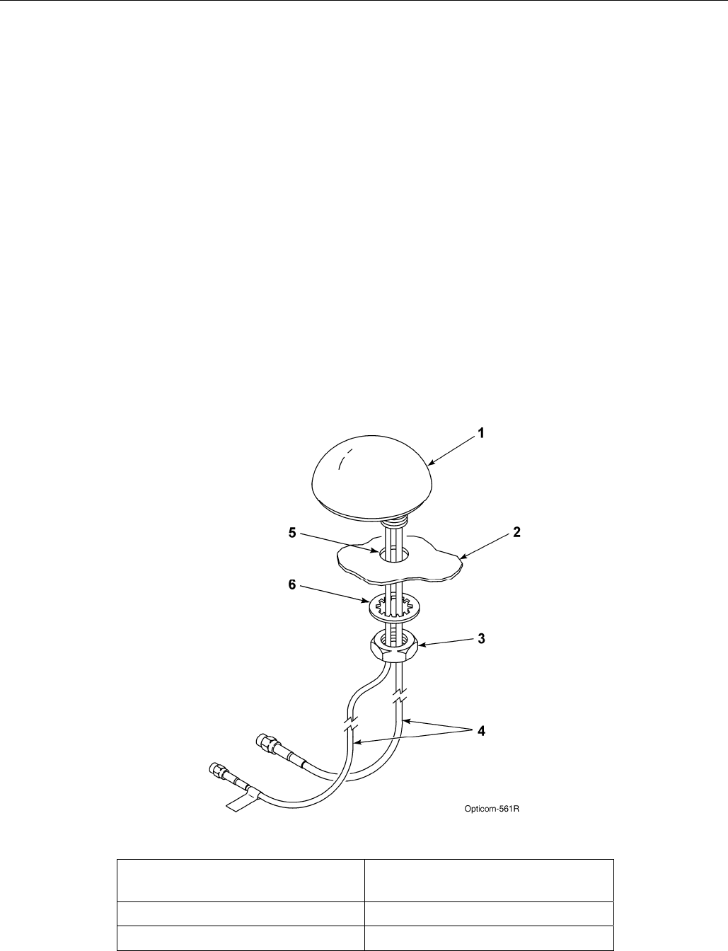
5.2 Model 1050 Radio/GPS antenna
installation
1. Remove the nut and washer from the
Radio/GPS antenna.
2. Drill a 5/8 to 3/4-inch hole. See Figure 5-2.
3. Route the cables through the hole. And
replace the lock washer and nut.
4. Tighten the nut with a15/16” wrench (a 24
mm wrench may be used if a 15/16’ wrench
is not available)
Note: Do not over tighten the nut or the
antenna may be damaged. 5 ft/lbs is the
recommended torque.
5. Apply silicone RTV (not provided) around the
antenna if the roof curvature prevents a good
seal with the antenna’s built-in gasket.
6. If necessary alternate mounting brackets are
available for mounting on vehicle mirrors,
vertical posts and trunk lids. These brackets
are available from Mobile Mark
Communications Antennas
(www.mobilemark.com, 1-800-648-2800).
The part numbers are SM-MM (mirror mount)
and SM-TM (trunk lid mount). When using
these mounts, GTT recommends that the
bottom of the antenna where the cables exit
be sealed with RTV. Also care should be
taken to protect the cables where they enter
into the vehicle.
7. An adapter for thicker roofs is available.
Contact GTT Technical Service at 1-800-
258-4610 for details.
Figure 5-2. Mounting Radio/GPS Antenna on Priority Vehicle
1. Vehicle radio/GPS antenna 4. Radio and GPS antenna
cables
2. Vehicle mounting surface 5. 5/8 to 3/4-inch mounting hole
3. Antenna nut 6. Antenna lock washer
Vehicle Equipment Installation Instructions
14
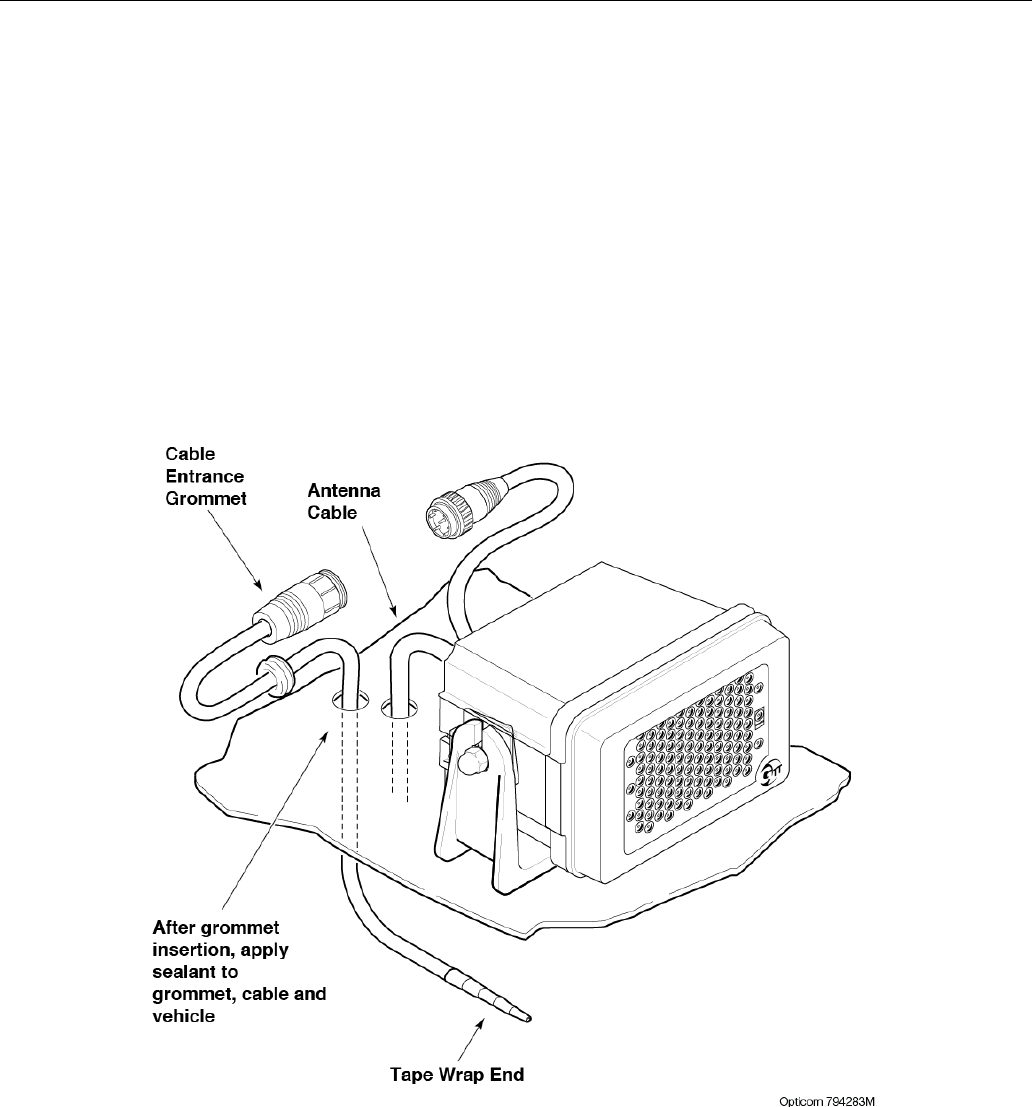
5.3 Model 794HM, Model 794TM
This section describes the use of the Model
794HM and the 794TM multimode emitters. The
multimode emitter contains an infrared LED
emitter. The multimode emitters also contain
radio and GPS antennas that perform the same
function as the Model 1050 radio/GPS antenna
described in section 5.2.
1. Refer to the manual that was included with
the Model 794HM or 794TM for details on
installation.
2. Proceed to section 5.4.
Figure 5-3. Model 794HM, 794TM multimode emitter
Vehicle Equipment Installation Instructions 15
5.4 Radio/GPS Unit Cable Terminations
1. Route the cables from the radio/GPS
antenna through the vehicle to the radio/GPS
unit location.
2. Coil up any excess cable.
Note: When coiling excess cable do not
create any sharp bends in the cable or
the cable may be damaged.
3. Connect the cable labeled GPS to the GPS
connector on the radio/GPS unit. Connect
the other cable to the Radio connector.
Tighten the connectors using a 5/16” wrench
(an 8 mm wrench may also be used).
Note: The connectors are keyed and
cannot be connected to the wrong
connector.
Note: To avoid damage to the equipment
always connect the GPS and Radio
connectors before connecting the
radio/GPS cable. Never operate the
equipment with the antenna cables
disconnected.
Also be sure that the end of the
radio/GPS cable that connects to the
Vehicle control unit is plugged in AFTER
the 15-pin connector is plugged into the
radio/GPS unit.
4. Plug the 15 pin connector of the radio/GPS
cable (black cable) into the P1 connector of
the radio/GPS unit and tighten the screws.
5. Route the cable to the location where the
Vehicle Control unit will be installed.
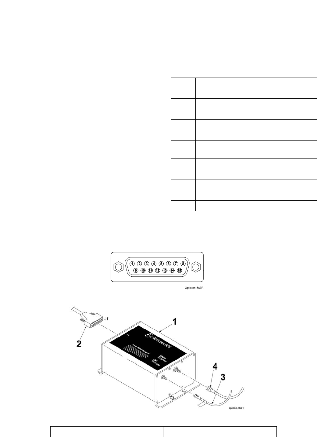
Table 5-1. Radio/GPS Cable Connector
Pin Index
Pin Wire Color Function
1 Yellow Radio transmit (+)
2 Yellow Black Radio transmit (–)
4 Blue Radio receive (+)
5 Blue White Radio receive (–)
7 Orange Radio clock (+)
8 Orange
Green Radio clock (–)
9 Brown GPS power
11 Brown White Common
12 Violet White Common
13 Bare Shield drain wire
15 Violet Radio power
Figure 5-5. Radio/GPS Cable Installation
1. Vehicle radio/GPS unit 3. GPS antenna cable
Figure 5-4. Radio/GPS Cable Connector Pin
Configuration
Vehicle Equipment Installation Instructions
16
2. Radio/GPS cable assembly 4. Radio antenna cable
5.5 Vehicle Control Unit Installation
This subsection describes the installation of
the Opticom™ GPS System Vehicle Control
Unit. It also describes connecting the
radio/GPS cable from the radio/GPS unit to
the control unit and connecting the vehicle
interface harness to the control unit.
Please read and fully understand the
following precautionary paragraphs before
installing the control unit.
Installations may include a customer-supplied
disable switch in addition to the control unit.
The Disable feature disables the priority
request when the disable switch closes to
battery negative or positive. This feature
typically uses an existing switch that indicates
the presence of conditions deemed
appropriate to disable the priority request,
such as opening the vehicle operator’s door.
The control unit must not be in the path of
airbag deployment.
Use care when drilling holes to avoid drilling
into undesirable locations.
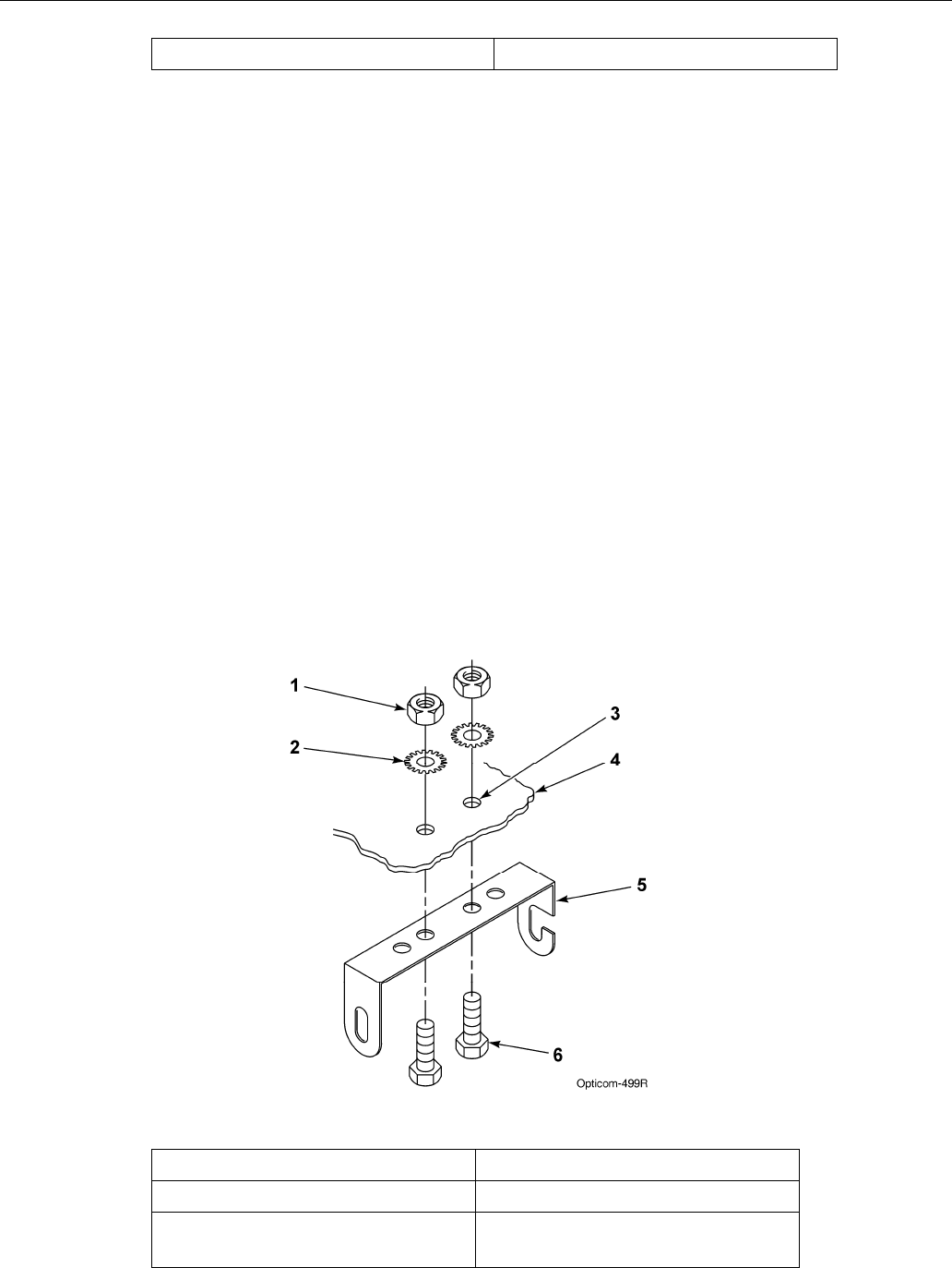
1. Determine the desired location to
mount the vehicle control unit. Mark
and drill two 7/32-inch holes, using the
control unit mounting bracket as a
template.
2. Insert the two 10-32 x 3/4-inch cap
screws through the holes in the mounting
bracket and mounting surface. See
Figure 5-6.
3. Use the two lock washers and 10-32 nuts
to secure the bracket to the vehicle.
Figure 5-6. Control Unit Mounting Bracket Installation
1. 10-32 nut (2) 4. Mounting surface
2. Lock washer (2) 5. Mounting bracket
3. 7/32-inch hole (2) 6. 10-32 x 3/4-inch cap screw
(2)
Vehicle Equipment Installation Instructions
17
4. Cut the Radio/GPS cable (black cable) to the
proper length.
5. Strip approximately 3 inches of the outer
jacket from the end of the cable. Be careful
not to cut the wires inside.
6. Strip 1/4 inch of insulation from each wire.
Note: It is very important not to strip too
much insulation, which may lead to short
circuits; or too little insulation, which may
prevent the wire from making good
contact.
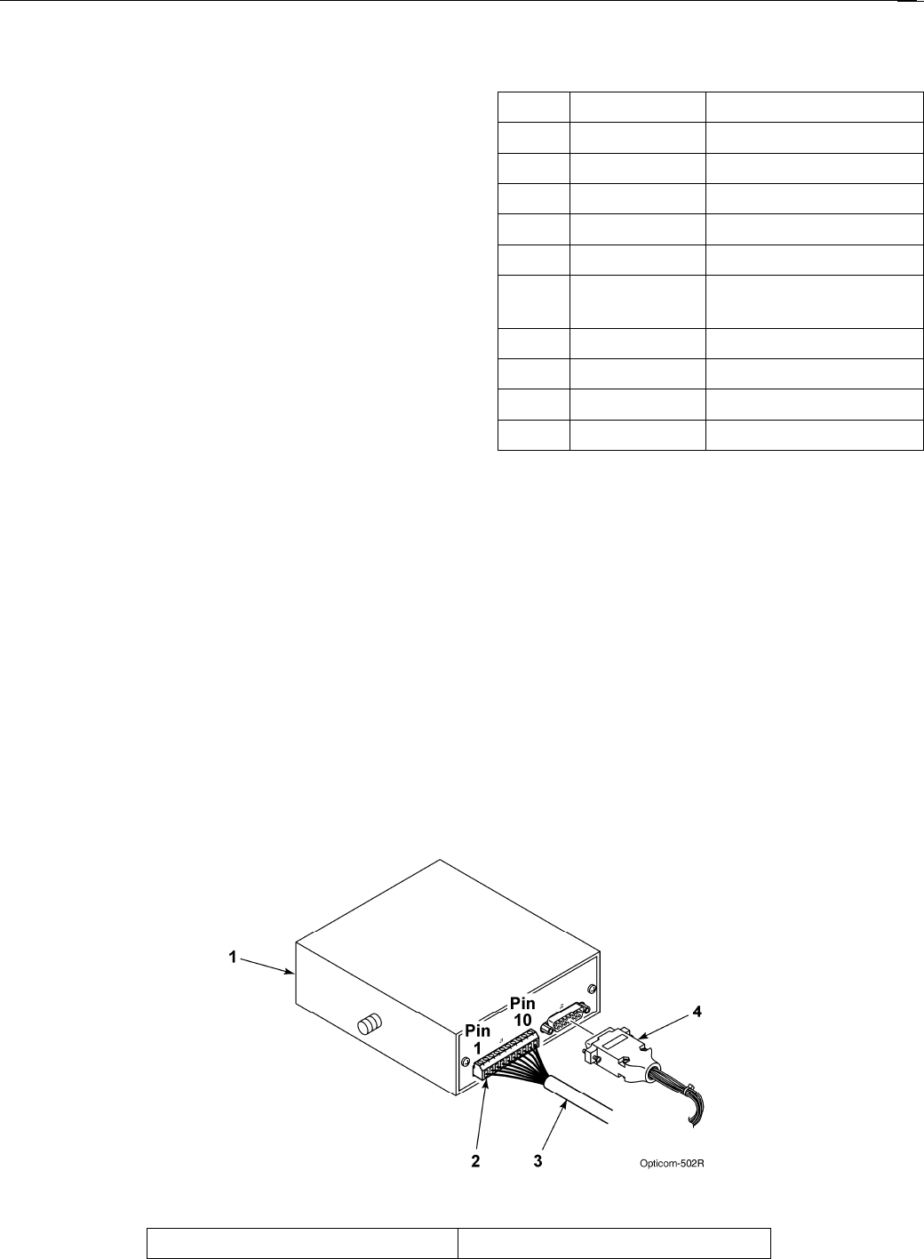
7. Place each wire into the appropriate terminal
in the 10-pin terminal block located on the
back of the control unit and tighten the screw
to secure the wire. The label on the terminal
block shows the color for each wire. Table
5-2 also shows the terminal block pin
number, wire color, and function for each
wire. See Figure 5-7.
The terminal block may be removed from
the control unit to allow easier
connections.
8. Cut the bare wire off even with the edge of
the outer jacket of the cable.
9. Plug the vehicle interface harness into the
15-pin connector on the back of the control
unit and tighten the screws. See Figure 5-7.
Note: Be sure that the end of the
radio/GPS cable that connects to the
Vehicle control unit is plugged in AFTER
the 15-pin connector is plugged into the
radio/GPS unit.
Table 5-2. Control Unit Terminal Block
Pin Index
Pin Wire Color Function
1 Yellow Radio transmit (+)
2 Yellow Black Radio transmit (–)
3 Blue Radio receive (+)
4 Blue White Radio receive (–)
5 Orange Radio clock (+)
6 Orange
Green Radio clock (–)
7 Brown GPS power
8 Brown White Common
9 Violet Radio power
10 Violet White Common
Figure 5-7. Vehicle Control Unit Wiring
1. Vehicle control unit 3. Radio/GPS cable
Vehicle Equipment Installation Instructions
18
2. 10-pin terminal block 4. Vehicle interface harness
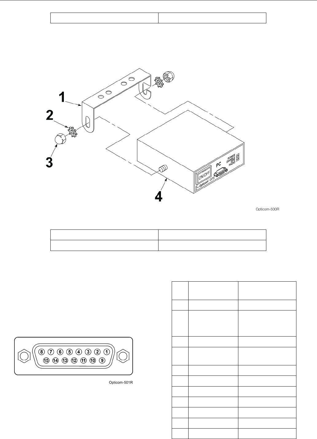
10. Place the control unit into the mounting
bracket. Use the two 1/4-inch acorn nuts
and lock washers to secure the control unit
to the bracket. See Figure 5-8.
Figure 5-8. Vehicle Control Unit Installation
1. Mounting bracket 3. Acorn nut (2)
2. Lock washer (2) 4. Vehicle control unit
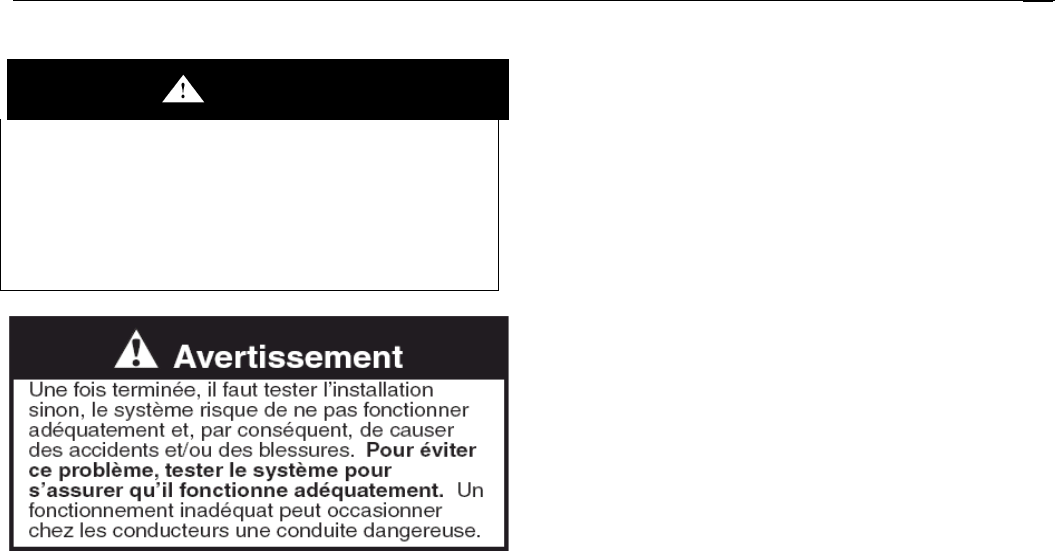
11. Route the wires of the vehicle interface
harness to the appropriate connection points.
Table 5-3 shows the connector socket pin
number, wire color, and function for each
wire. Figure 5-9 shows the socket view of
the harness connector. All wires may not be
used in all installations.
Figure 5-9. Interface Harness Connector Pin
Configuration
Table 5-3. Interface Harness Connector Pin
Index
Pi
n Wire Color Function
1 White/Yellow J1708 (+)
2 Blue Lightbar sense
or
Ignition switch
3 Brown Low priority
4 Gray Probe/GPS
always out input
6 White Disable sense
7 Green Right turn sense
8 Yellow Left turn sense
9 Black Ground
10 Red +12 VDC
13 White/Orange GPS TXD (-)
14 White/Brown GPS TXD (+)

Vehicle Equipment Installation Instructions
19
15 White/Blue J1708 (-)

Vehicle Equipment Installation Instructions
20
5.5.1 Turn Signal Sensing Connections
The turn signal sensing circuit operates by
detecting the change of state or flashing of the
vehicle’s turn signal circuits. If the turn signal
sense circuit detects both the left and the
right signal sense lines changing or flashing,
the vehicle equipment will transmit that it is
going straight.
This can be verified by monitoring the turn signal
inputs with the View Inputs Sensing screen or
vehicles heard screen in ITS Explorer.
1. Activate the left turn signal.
2. Press the brake pedal.
3. If you see the right (opposite) turn signal
sense change from active to inactive or vice-
versa. You will need to find another place to
connect to the vehicles turn signals.
Note: there is a 3 second delay before the
turn signal status will register. Press the
brake pedal several times and hold it for at
least 3 seconds.
This occurs because; in some vehicles the brake
light bulb is shared with the turn signals. If this
is the case, applying the brakes while either turn
signal is on will cause the turn signal sensing
circuit to think that both inputs are active and
cause the vehicle to transmit that it is going
straight.
Therefore it is recommended that the yellow and
green turn signal sense lines be connected only
to the front turn signal wires.
1. Connect the yellow wire from the harness to
the vehicle’s front left turn signal line.
2. Connect the green wire from the harness to
the vehicle’s front right turn signal line.
5.5.2 Additional Vehicle Connections
1. Connect the white wire to a switch that
actuates when the driver reaches the scene
and steps out of the vehicle. For instance,
this could be a door switch. The switch may
provide either +12 VDC or a ground. You
will need this information to set the Operating
mode (see Section 6.1, Configuration Setup
and Checkout).
Note: If the white disable line is not to be
used it is recommended that this wire be
connected to Ground. The disable mode
should then be set to Ground -> 12VDC and
non-latching.
2. Connect the blue wire to one of the provided
fuse holders. Connect the other end of the
fuse holder as described in either step a or b
below.
Do not install the fuse yet.
a. Connect the fuse holder to a point that
provides +12 VDC only when the lightbar is
turned on. This enables the driver to activate
the system when the lightbar is on by
pushing the ON/OFF switch on the control
unit to the ON position.
b. Connect the fuse holder to a point that
provides +12 VDC when the ignition switch is
in the RUN position. This enables the driver
to activate the system when the ignition
switch is on by pushing the ON/OFF switch
on the control unit to the ON position.
3. Install the fuse rating label on the blue wire
near the fuse holder.
4. Connect the red wire to the provided fuse
holder. Connect the other end of the fuse
holder to a +12 VDC power source that
provides at least 2 amps at all times. In
order for the GPS receiver to maintain an
accurate location, the receiver requires a
constant +12 VDC power source.
GTT recommends using a direct connection to
the battery. If this is not possible, use a terminal
block with a direct connection to the battery.
Do not install the fuse yet.
5. Install the fuse rating label on the red wire
near the fuse holder.
6. Connect the black wire to vehicle chassis
ground (DC–). Again, it is recommended
that this connection be made directly to the
battery or to a terminal block with a direct
connection to the battery.
7. Verify that the control unit on/off switch is set
to the OFF position.
8. Inspect all connections and verify that the
wiring is complete and accurate as described
in this installation manual.
9. Install the fuses (2A, 250V) in the fuse
holders.
10. Connect the vehicle’s positive battery cable,
then connect the negative battery cable.

Vehicle Equipment Installation Instructions
21
5.5.3 Low Priority
When Opticom™ GPS vehicle equipment ships
from the factory, the priority level (High or Low)
is preset. The user cannot change this priority
level. However, a high priority vehicle may be
set to temporarily be a low priority vehicle. This
feature is useful for traffic department
maintenance vehicles that maintain Opticom
GPS intersection equipment where both high
and low priority vehicles operate.
Low Priority Connections:
The vehicle interface harness contains a brown
wire that when connected to +12 VDC will cause
the vehicle unit to temporarily broadcast that it is
a low priority vehicle (see Table 5-3).
1. Connect the brown wire to one side of a
switch (not provided) and connect the other
side to +12 VDC.
2. Install an in-line fuse holder with a 2A, 250V
fuse (not provided).
3. When you activate the switch, the vehicle
will be a low priority vehicle until the switch
is deactivated.
Do not connect the Brown wire if
you do not want to use the mode
described above.
This action may be observed using the Vehicles
Heard section of ITS Explorer. Refer to the GPS
Vehicle Configuration section of the Opticom™
GPS System Operation Manual.
5.5.4 Probe Priority/GPS always out
The user has the option of activating the
Opticom GPS vehicle unit in a mode that will
allow the vehicle to transmit its position
information and output GPS data via a com port
without requesting TSP/preemption. This is
done by connecting the gray wire to +12VDC.
When +12 VDC is applied to the Gray wire, the
vehicle equipment will broadcast that it is in
Probe priority (will not request TSP/preempt).
Then one of the communication ports may be
configured to output GPS data in the NMEA
format. This data may be sent to other onboard
devices or computers to display the vehicles
current position speed and heading.
Notes:
1. See the Technical Bulletin “Vehicle
Connections and Configuration to obtain
GPS serial data for other Devices” or
section 9 of this document for details on
how to make these connections.
Do not connect the Gray wire if you
do not want to use the mode
described above.

Vehicle Equipment Installation Instructions
22
6 Checkout
This section describes how to check out and test
the installed Opticom™ GPS System.
6.1 Configuration Setup and Checkout
Using the Vehicle Configuration window of the
ITS Explorer application, configure the vehicle
control unit with the following parameters: (See
the on-line Help files and the Operation Manual
for additional information.)
Using the General Configuration window, set the
following parameters:
Configuration
Vehicle Name
Up to 40 alphanumeric characters
Agency ID
1 – 254
Vehicle Class
1 – 15
Vehicle ID
1 – 9999
Operating Mode
Disable Mode
Latching or Non-Latching
Disable Trigger method
+12 VDC to Ground
Ground to +12 VDC
GPS Receiver Power Options
Always On
Standby
6.2 Input Verification
1. Open the Vehicle Configuration window in
ITS Explorer.
2. Using the Diagnostic Activity window, open
the View Inputs Sensing window and activate
the left turn signal followed by the right turn
signal. Verify that the vehicle equipment
detects each input. You may also use the
vehicles heard window.
If both signals are being detected when only
the left or right signal is activated, it may be
necessary to connect the turn signal line to
another point.
3. Activate the disable switch and verify that the
vehicle equipment detects this action. Also
observe the DISABLE indicator and the
ON/OFF switch indicator. Both indicators will
be flashing green when the disable switch is
activated. See Table 6-1.
4. Verify that Disable mode activation is correct.
If Latching Disable mode is used, the vehicle
control unit stays in Disable mode after the
disable switch is returned to its normal state.
Turning the vehicle control unit off for a few
seconds and then back on removes the
Disable mode.
If Non-Latching Disable mode is used, the
vehicle control unit removes the Disable mode
as soon as the disable switch is returned to its
normal state.
Table 6-1. Vehicle Control Unit Indicators
Indicator Color or
Condition
Meaning
POWER Green Power applied to unit
ON/OFF
Switch Green
Flashing
Green
Power applied to unit
Vehicle in Disable
mode
DISABLE Off
Amber
Flashing
Green
Vehicle NOT in Disable
mode
Vehicle is transmitting
“Probe” mode
Vehicle in Disable
mode
GPS Amber
Green
Not receiving GPS,
radio not transmitting
GPS has good 3D fix
RADIO Amber
Green
No communication
between radio/GPS
unit and vehicle control
unit
Good communication
between radio/GPS
unit and vehicle control
unit
Vehicle Equipment Installation Instructions
23
6.3 Performance Tests
WARNING
A completed installation that is not tested may
result in improper system operation, which may
result in accidents and/or injuries. To avoid
this problem, test the system to verify proper
operation. Improper system operation may
result in unsafe driver action.
These installation instructions are the result of
tests performed in our laboratory and we believe
these tests to be accurate and complete.
However, each installation involves variables
that cannot be controlled or predicted. These
variables may affect the operational
characteristics of the system.
To ensure proper system operation, GTT strongly
recommends that, when the system is turned on,
the installer functionally tests the system using
the following procedure.
1. Place the Opticom GPS-equipped vehicle in
an area with GPS coverage. This is either
outdoors, away from nearby buildings and
overhanging trees, or inside of a garage that
has adequate GPS coverage.
2. Verify that the vehicle equipment acquires
GPS.
Turn the vehicle control unit on by pressing the
ON/OFF switch. The unit should acquire GPS
within a few minutes; however, it may take up
to 15 minutes. A green GPS indicator means
that GPS has been acquired. An amber GPS
indicator means that GPS has not been
acquired. If GPS has not been acquired within
15 minutes, turn the control unit off and wait
another 15 minutes. Then turn it back on. If
the unit still has not acquired GPS, verify that
your location has a good view of the sky. If
you are unable to acquire GPS, contact GTT
Technical Service or your dealer.
3. Verify that the vehicle radio/GPS unit is
transmitting information properly. The
vehicle radio/GPS unit will not operate if the
system has not acquired GPS. Therefore,
this check cannot be completed unless you
have GPS.
Place the vehicle to be tested in close
proximity of another known good Opticom
GPS-equipped vehicle or intersection. This
vehicle or intersection also must have good
GPS coverage.

Vehicle Equipment Installation Instructions
24
If a vehicle is used, its radio must be placed
in Transmit mode because vehicle radios will
not transmit unless they hear an intersection
radio. Open the View Inputs Sensing
window and select the Transmit Test tab.
Press the Test Mode button. The vehicle
radio will now transmit even if it does not
hear an intersection radio. The vehicle radio
will stay in this mode until the next power
cycle.
Note: If an intersection is used for this
test, activate the vehicle’s disable switch
or you will be placing priority requests to
the intersection controller. Therefore, it
is recommended that another Opticom
GPS-equipped vehicle be used for
testing.
Open the Vehicles & Intersections Heard
window under the Real Time Activity section
in ITS Explorer. This window is duplicated in
both the Vehicle and Intersection modules of
ITS Explorer. Verify that you are receiving the
correct following parameters from the vehicle
under test.
Agency ID
Class ID
Vehicle ID
Priority
You should also receive the following
information from the vehicle under test. You
will not be able to verify the values, but you
need to verify that the information is being
transmitted. Examples:
Latitude and Longitude
Heading and Velocity
Fix Type
Position Dilution
Horizontal Dilution
Satellites
Activate the left turn signal, the right turn
signal, the disable switch and verify that the
correct information is being transmitted. This
verifies that the vehicle under test is set up
correctly and is transmitting all required
information.
4. Verify that the vehicle radio/GPS unit is
receiving information properly.
Connect the computer running ITS Explorer to
the vehicle under test and repeat the above
procedure looking for the data being
transmitted from your known good vehicle or
intersection equipment. This verifies that the
vehicle under test is receiving all required
information.

Vehicle Equipment Installation Instructions
25
7 Troubleshooting
Table 7-1 shows the symptoms of
the Opticom™ GPS System Vehicle
Equipment installation problems. The table
also shows the possible causes of those
problems and suggests solutions to correct
them.
Table 7-2 shows the expected voltages at
various wiring terminals.
Table 7-1. Troubleshooting Symptoms, Possible Causes, and Solutions
Symptom Possible Cause Solution
Vehicle control unit POWER LED
will not light. Wiring incorrect. Check wiring. Verify that control
unit is getting 12 VDC.
Remote activation line not active. Verify that 12 VDC is being
applied to blue wire of vehicle
interface harness.
Fuse/s blown Replace fuses with 2A/250V 3AG
SLO-BLO.
Vehicle control unit failed. Return unit to GTT for service.
Times in log are incorrect. Time localization not set, or set
incorrectly. Set correct time zone for your
area.
GPS will not acquire.
(GPS LED is amber.) Initial start-up may take up to 15
minutes. Wait 15 minutes.
Radio/GPS unit’s view of sky is
obstructed. Move unit or remove
obstructions.
RF interference. Turn off vehicle control unit for 15
minutes, then try again.
Incorrect wiring. Check wiring at both ends of
radio/GPS cable.
Radio/GPS cable connector
(terminal block) plugged in
backwards.
Plug in terminal block correctly.
Radio/GPS unit failed. Return unit to GTT for service.
Radio/GPS antenna failed. Return unit to GTT for service.
Vehicle control unit failed. Return unit to GTT for service.
No power to GPS receiver. Check voltage between brown
(+) and brown/white (–) wires at
both ends. It should be about 8.3
VDC.

Vehicle Equipment Installation Instructions
26
Table 7-1. Troubleshooting Symptoms, Possible Causes, and Solutions (continued)
Symptom Possible Cause Solution
RADIO LED is amber. Incorrect wiring. Check wiring at both ends of
radio/GPS cable.
Radio/GPS cable connector
(terminal block) plugged in
backwards.
Plug in terminal block correctly.
Radio/GPS cable damaged or
poor terminations. Replace cable, redo
terminations.
Radio/GPS unit failed. Return unit to GTT for service.
Vehicle control unit failed. Return unit to GTT for service.
No power to radio. Check voltage between violet (+)
and violet/white (–) wires. It
should be about 9.0 VDC.
Unable to communicate with
vehicle control unit. Communication cable not
connected. Check cable connection at
vehicle control unit and at
computer.
Baud rate/serial port incorrect. Using ITS Explorer, change baud
rate/serial port under
Environment options.
Intersection Name not Heard
listed instead of intersection
name.
Name not heard yet. Press Get Intersections Heard
button again.
Cycle power on vehicle control
unit.
Name not assigned in
intersection. Assign an intersection name.
Intersection alternates displaying
and dropping the left turn arrow
when approaching vehicle has
left turn signal activated.
Vehicle brake light bulb shared
with turn signal indication.
Emergency flashers are active.
Controller or phase selector not
programmed correctly.
Reconnect vehicle turn signal
sense lines to front turn signal
wires.
Turn of emergency flashers
Reprogram controller or phase
selector.
Vehicle does not enter disable
mode when activated Incorrect disable trigger mode
has been set Verify that you have set the unit
to reflect how the disable line is
wired 12 VDC to Ground or
Ground to 12 VDC
Intersection does not display left
turn arrow when approaching
vehicle has the left turn signal
activated.
Vehicle brake light bulb shared
with turn signal indication.
Emergency flashers are active.
Controller or phase selector not
programmed correctly.
Reconnect vehicle turn signal
sense lines to front turn signal
wires.
Turn off emergency flashers
Reprogram controller or phase
selector.
Table 7-2. Expected Voltages

Vehicle Equipment Installation Instructions
27
Location/Terminal Expected Voltage Notes
Red to Black wires on harness 12 VDC Check fuse.
Blue wire on harness 12 VDC Must have 12 VDC to activate
system, check fuse.
Brown to Brown/White Approximately 7.15 VDC GPS power source, check for at
least 5 seconds.
Violet to Violet/White Approximately 7.75 VDC Radio receiver power source,
check for at least 5 seconds.
8 Maintenance
Opticom™ GPS system components are
designed for reliable operation. Inspect the
components at regular intervals to ensure
proper system operation.
GTT recommends the following:
Each intersection system and vehicle
system should be inspected and tested at
least every 12 months to ensure it functions
to your specifications and requirements.
Intersection systems should be tested with
known good vehicle systems.
Vehicle systems should be tested with
known good intersection systems.
You should develop a test plan that fits your
department’s operations and meets the
needs of your system.
You should keep accurate and up-to-date
records of system performance and test
results.
Note: When washing the vehicle, avoid
pointing a high-pressure washer at the
radio/GPS antenna.

26 Vehicle Equipment Installation Instructions
9 GPS Output Function
The Opticom™ GPS system utilizes information
from the constellation of GPS satellites. This
data may also be used by other devices that
are installed in an Opticom GPS equipped
vehicle This section provides details on the
format of the GPS data as well as details on
how to connect to the Opticom GPS equipped
vehicle to obtain this data.
Caution Notes
The Global Positioning System (GPS) is
operated by the United States government,
which is solely responsible for its accuracy and
maintenance. The system is subject to changes
which could affect the accuracy and
performance of all GPS equipment. Although
the Opticom GPS system uses a precise GPS
receiver, any navigation system can be
misused or misinterpreted and therefore
become unsafe. It is the user’s responsibility to
use this position information prudently. This
information is intended to be used only as a
navigational aid and must not be used for any
purpose requiring precise measurement of
direction, distance, location or topography. Use
this product at your own risk. To reduce the
risk, carefully compare indications from the
GPS to all available navigation sources
including the information from any other
NAVAIDS, visual sightings, maps etc. For
safety, always resolve any discrepancies before
continuing navigation.
Format and data available
The Opticom GPS system will output serial
GPS data in the NMEA 1083, v2.0 or later
format. The following messages are
provided:
GGA Global Positioning System Fix Data
GSA GPS DOP and active satellites
GSV Satellites in view
RMC Recommended Minimum Navigation
Information
Vehicle Connections and Configurations
This section describes the necessary
connections and configuration to obtain the
available GPS data from Opticom GPS vehicle
equipment.
Connections
1. Connect the White/Orange (GPS
TXD -) wire of the Vehicle interface
harness to pin 2 on a DB-9 or DB-
25 connector.
2. Connect the black (Ground) wire of
the Vehicle interface harness to pin
5 on a DB-9 or DB-25 connector.
3. Connect the DB-9 or DB-25
connector to the device that will
receive the GPS data.
Configuration
1. Open ITS Explorer and go the
Vehicle Configuration section.
2. Go to the General Configuration
section and select GPS Port from
the Communications Section.
3. Verify that the protocol is set to
“GPS Receiver NMEA Messages”
4. The sentences that are available
will depend on the baud rate that
you select in the communication
section of ITS Explorer.
a. 1200 Baud RMC only
b. 2400 Baud RMC, GGA and
GSA
c. 4800 Baud and higher
RMC, GGA, GSA, GSV
5. Press the “Write to Device” Button
to apply the changes to the vehicle
unit.
Notes:
1. The GPS data is only available when
the vehicle unit is fully powered and
requesting preemption/TSP. If you also
need to have GPS data available when
not in preemption /TSP mode See the
Technical Bulletin “Vehicle Connections
and Configuration to obtain GPS serial
data for other Devices” for details on
how to make these connections.

Important Notice to Purchaser:
EXCEPT FOR THE LIMITED WARRANTIES SET FORTH IN THIS DOCUMENT, GLOBAL
TRAFFIC TECHNOLOGIES (GTT) MAKES NO OTHER WARRANTIES AND EXPRESSLY
DISCLAIMS ALL OTHER WARRANTIES, WHETHER EXPRESS OR IMPLIED, INCLUDING,
WITHOUT LIMITATION, ANY WARRANTY AS TO MERCHANTABILITY OR FITNESS FOR A
PARTICULAR USE.
GTT will, at its sole option, repair, replace or refund amounts paid for any OpticomTM System
component found to be defective in materials or manufacture during the warranty period.
GTT warrants future system operability coverage as described herein. This warranty shall not
apply to any OpticomTM system components which have been (1) repaired or modified by
persons not authorized by GTT; (2) subjected to incorrect installation, misuse, neglect or
accident; (3) damaged by extreme atmospheric or weather-related conditions, flood, fire,
vandalism, crime or other events beyond the reasonable control of GTT; or (4) subjected to
events or use outside the normal or anticipated course.
IN NO EVENT SHALL GTT BE LIABLE FOR ANY INJURY (INCLUDING, WITHOUT
LIMITATION, PERSONAL INJURY), DEATH, LOSS, OR DAMAGE (INCLUDING, WITHOUT
LIMITATION, PROPERTY DAMAGE), WHETHER DIRECT, INDIRECT, INCIDENTAL,
SPECIAL, CONSEQUENTIAL, OR OTHERWISE, ARISING OUT OF THE USE OR INABILITY
TO USE, REPAIR OR FAILURE TO REPAIR, ANY GTT PRODUCT, REGARDLESS OF THE
LEGAL
THEORY ASSERTED. THE REMEDIES SET FORTH IN THIS DOCUMENT ARE EXCLUSIVE.
Sale and use of the Opticom TM System is expressly restricted to authorized agencies of
government customers, within their specific jurisdictions. However, because the signal
generated by the Opticom™ system may not be exclusive, GTT does not warrant exclusive
activation by purchaser. Authorized users who desire to use or coordinate use of the OpticomTM
system with that of other jurisdictions must first obtain the prior written approval of each
authorized user in the jurisdiction where use is sought.
Since the availability of a GPS signal is out of GTT’s control and is required for OpticomTM GPS
system operations, GTT does not warrant against OpticomTM GPS system failures due to the
unavailability of the GPS signal for any reason.
Global Traffic Technologies, LLC Global Traffic Technologies Canada,
Inc.
Opticom and the GTT logo mark are
trademarks
7800 Third Street North 157 Adelaide Street West of Global Traffic Technologies, LLC
St. Paul, Minnesota 55128-5441 Suite 448 Please recycle. Printed in the U.S.A.
1-800-258-4610 Toronto, ON M5H 4E7 © Global Traffic Technologies, LLC 2011
651-789-7333 Canada All rights reserved.
www.gtt.com 1-800-258-4610 75-0301-0693-6 Rev. K