Global Traffic Technologies OPTICOMGPS3 Opticom GPS Priority System User Manual RF Module Serial Protocol
Global Traffic Technologies, LLC Opticom GPS Priority System RF Module Serial Protocol
User Manual

Copyright © 2000-2013, Global Traffic Technologies, LLC
79-1000-0772-0
Revision B
OPTICOMGPS3 Radio Transceiver Module
User Manual

Page 2 of 31
Copyright © 2000-2013, Global Traffic Technologies, LLC
Ownership Disclaimer
This document contains confidential information that is the sole property of Global Traffic
Technologies (GTT) and is intended for use by their employees and designees. The user shall keep
the contents of this document confidential and protect it from disclosure to outside parties. Any
copying, distribution, or re-use, either in part or in whole, without the express written consent of
Global Traffic Technologies is prohibited.
Trademark Conventions
The following is the list of registered trademarks of Global Traffic Technologies:
Opticom®
All instances of Opticom, Opticom Infrared and Opticom GPS contained within this document are understood
to reference these trademarks without repeating the ® symbol.

Page 3 of 31
Copyright © 2000-2013, Global Traffic Technologies, LLC
Table of Contents
1. INTRODUCTION ........................................................................................................................... 4
1.1 Scope .......................................................................................................................................................................................... 4
1.2 Definitions, Acronyms, and Abbreviations ....................................................................................................................... 4
2. PROTOCOL SPECIFICATION ...................................................................................................... 5
2.1 Roles ............................................................................................................................................................................................ 5
2.2 Error Detection & Recovery................................................................................................................................................... 5
2.3 Flow Control .............................................................................................................................................................................. 5
2.4 Character Format ..................................................................................................................................................................... 5
2.5 Supported Data Types ............................................................................................................................................................ 6
2.6 Message Format ....................................................................................................................................................................... 6
3. SETUP AND CONFIGURATION MESSAGES .............................................................................. 8
3.1 Set Mode (M) .............................................................................................................................................................................. 8
3.2 Set Framing Configuration (F) .............................................................................................................................................. 9
3.3 Hop Table Configuration (H) ............................................................................................................................................... 10
3.4 Hop Table Row Index (I) ....................................................................................................................................................... 14
3.5 Transmit Slot Data (T) ........................................................................................................................................................... 15
3.6 Receive Slot Data (r) .............................................................................................................................................................. 16
3.7 Broken Mode Report (b) ....................................................................................................................................................... 17
3.8 Signal Strength Report (s) ................................................................................................................................................... 17
3.9 Set Serial Number (N) ............................................................................................................................................................ 18
3.10 Set Attenuation Level (G) ......................................................................................................................................................... 19
3.11 Erase Faults (J) ......................................................................................................................................................................... 20
4. QUERY MESSAGES ................................................................................................................... 21
4.1 Module Identity Query (D) .................................................................................................................................................... 21
4.2 Mode Query (Q) ....................................................................................................................................................................... 22
4.3 Framing Configuration Query (C) ...................................................................................................................................... 23
4.4 Hop Table Configuration Query (A) ................................................................................................................................... 24
4.5 Broken Mode (B) ..................................................................................................................................................................... 25
5. HARDWARE INTERFACE .......................................................................................................... 26
6. AGENCY STATEMENTS ............................................................................................................ 27
7. REVISION HISTORY ................................................................................................................... 31

Page 4 of 31
Copyright © 2000-2013, Global Traffic Technologies, LLC
1. Introduction
Scope
This specification defines and controls the serial communications interface between the Global Traffic Technologies
(GTT) Radio Module controller and the RF module controller through which the configuration and control of the RF
module is performed.
Definitions, Acronyms, and Abbreviations
This section contains descriptions of terms, acronyms, and abbreviations that are used throughout this document.
3D – Three dimensional
RF – Radio Frequency
PPS – Pulse Per Second
Page 5 of 31
Copyright © 2000-2013, Global Traffic Technologies, LLC
2. Protocol Specification
The following subsections detail the structure of the protocol. Individual message types are defined in the next major
section.
Roles
This protocol is intended to be used in a point-to-point mode only meaning one GTT controller to one RF module. The
devices act as near peers in that the GTT device assumes the role of a master device in order to perform
configuration of the RF module. However, once operations have begun, the RF module autonomously reports inbound
data as it occurs while the GTT controller periodically sends content to be transmitted and the time index to be used
in frequency hopping.
Error Detection & Recovery
All devices are expected to detect framing, checksum and overflow errors. If a device detects a communication error
such as these, the device will not send a response to the received message. It is the sender’s responsibility to detect
the lack of response from the receiving device and resend the command if it so chooses. During configuration, the
GTT controller will perform retries to ensure that the RF module is fully configured prior to enabling over-the-air
operation.
If a device receives a message without error, but the message contains invalid data, or the requested operation
cannot be performed due to the current context of the receiving device, then the device is expected to provide
information in the response to the sender that it could not carry out the command.
Under operational conditions (i.e. over-the-air), the messages are transfers of data, not diagnostics or configuration.
Failure of a transfer (See annotations in the message section) shall not require a retry since loss of a single data is
non-critical (i.e. either repeated or new data will be arriving momentarily).
Flow Control
No flow control shall be supported by this protocol.
Character Format
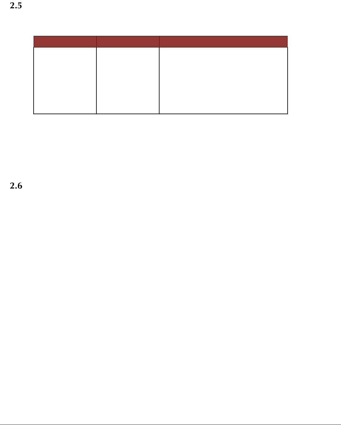
The supported binary character format is the following:
Start bits:
1
Data bits:
8
Stop bits:
1
Parity:
None
Page 6 of 31
Copyright © 2000-2013, Global Traffic Technologies, LLC
Supported Data Types
In order to specify the message formats, the following data type definitions are necessary:
Type
Size
Range
UCHAR
8 bits
0..255
CHAR
8 bits
-128..127
USHORT
16 bits
0..65535
SHORT
16 bits
-32768..32767
ULONG
32 bits
0..4,294,967,295
LONG
32 bits
-2,147,483,648..2,147,483,647
Each byte (where a byte is 8 bits in size) of these data types is serial transmitted least-significant bit first, most-
significant bit last. Multi-byte data types are transmitted least-significant byte first, most significant byte last. For
example, an unsigned short with value 1234H would be transmitted as a byte with value 34H followed by a byte with
value 12H (i.e. little endian).
Message Format
Messages are sent from the host to the radio in multiple of 8 bytes. For messages that are not even multiples of 8
bytes, the remaining package is padded with trailing zeros (0).
Messages have the following structure:
<Header><Length><Command><Data><Checksum>
with the fields further defined below:
<Header>
The <Header> shall be a single UCHAR with a value 0x02 representing an STX.
A message receiver begins assembling a new incoming message when it receives a <Header> meeting this
specification.
<Length>
16 bit value specifying the number of bytes to follow including the checksum.
<Command>
The <Command> is composed of a single ASCII CHAR. Commands are defined in section 5. Commands that are
initiated by the host are always an uppercase character. Commands that initiated by the RF module or responses
to host commands are always a lowercase character.
<Data>

Page 7 of 31
Copyright © 2000-2013, Global Traffic Technologies, LLC
The <Data> field is an optional, variable length field which has a format that is context dependent for each
<Message ID>. The maximum length for this field is not limited by the protocol.
<Checksum>
The <Checksum> field is a single USHORT field which is the 16-bit sum (sum modulo 216) of all the bytes in the
message prior to this field. This sum includes the <Header>,<Length>,<Command>, and <Data> fields.

Page 8 of 31
Copyright © 2000-2013, Global Traffic Technologies, LLC
3. Setup and Configuration Messages
Set Mode (M)
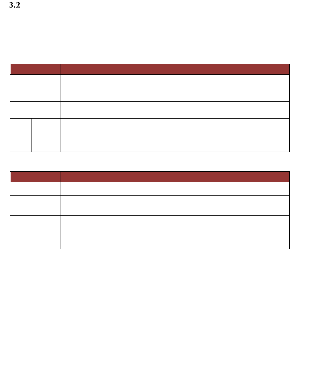
Used by the host to change the operational mode of RF module. Offline mode is an idle mode where operational
setup occurs. Online mode is an active operations mode where normal transmit and receive functions are performed.
Tests modes are receive test mode and transmit test mode. RF Module responds with the new active mode or a
Broken Mode status.
Offline Mode is characterized by no RF activity (transmitter off, receiver off) and no frequency hopping.
Online Mode is possible when the RF module has been completely configured.
Note: When enabled, programming mode may use a different protocol
Sent by Host:
Data Element
Base Type
Instances
Description
Length
USHORT
1
Number of bytes to follow including checksum. Always 4
for this message.
Command
UCHAR
1
Single ASCII character ‘M’ for mode.
Mode
UCHAR
1
Values are :
0 – Offline Mode
1 – Online Mode
2 – Transmit Test Mode
3 – Programming
Sent by RF Module:
Data Element
Base Type
Instances
Description
Length
USHORT
1
Number of bytes to follow including checksum. Always 5
for this message.
Command
UCHAR
1
Single ASCII character ‘m’ mode acknowledge.
Status
UCHAR
1
Values are:
0 – Accepted
1 – Invalid mode
2 – Cannot change mode, insufficient information or
setup
Current Mode
UCHAR
1
Values are :
0 – Offline Mode
1 – Online Mode
2 – Transmit Test Mode
3 – Programming
4 – Broken Mode
Page 9 of 31
Copyright © 2000-2013, Global Traffic Technologies, LLC
Set Framing Configuration (F)
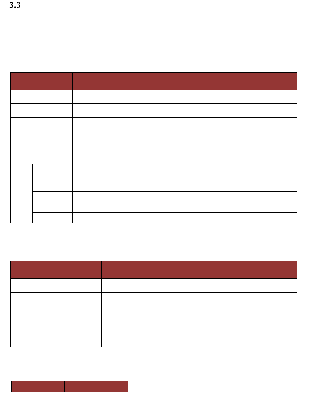
Used by the host to configure the number of slots to occur in each frequency hop, number of data slots, and the
individual slot configurations. All slots are assumed to be receive slots until configured otherwise.
Note: the first one or more slots of a frame may not be useable if the transmission time is less than 3.167 msec. This
time is needed by the radio to tune to the new frequency.
Sent by Host:
Data Element
Base Type
Instances
Description
Length
USHORT
1
Number of bytes to follow including checksum.
Value is 4 + (number of slots * 2).
Command
UCHAR
1
Single ASCII character ‘F’ for framing configuration.
Number of
slots/hop
UCHAR
1
Number of slots to follow. Maximum of 255 slots. Default
is 186.
For
each
slot
Slot
Size
USHORT
1
Number of bytes in this slot. Maximum size is dictated
by the number of slots. Total number of bytes sent per
frame cannot exceed 16,000.
Note: Slot sizes must be even number of bytes.
Sent by RF Module:
Data Element
Base Type
Instances
Description
Length
USHORT
1
Number of bytes to follow including checksum. Always 4
for this message.
Command
UCHAR
1
Single ASCII character ‘f’ for framing configuration
acknowledge.
Status
UCHAR
1
Values are:
0 – Accepted
1 – Invalid number of slots
2 – Invalid size
3 - Exceeds maximum byte total
Page 10 of 31
Copyright © 2000-2013, Global Traffic Technologies, LLC
Hop Table Configuration (H)
Used by the host to specify the set of frequencies to be used in the hopping sequence. Frequencies are specified in
rows and columns. Each row is indexed by the seconds since midnight calculated from the UTC time reported by the
GPS receiver modulo the number of rows. The host will calculate the seconds since midnight and row index each
second.
Sent by Host:
Data Element
Base
Type
Instances
Description
Length
USHORT
1
Number of bytes to follow including checksum. Value is
5 + (number of row * number of columns)
Command
UCHAR
1
Single ASCII character ‘H’ for hop table configuration.
Number of rows
UCHAR
1
Number of seconds before repeating. Maximum of 25
rows. Default is 25.
Number of columns
UCHAR
1
Number of frequency changes per second. Maximum of
5 columns. Default is 3.
Note: rows * columns MUST be less than or equal to 75.
For
each
row
Channel 1
UCHAR
1
Receive channel for 1st hop in this second. Integer
channel value. Valid range is 1 to 81.
Channel 2
UCHAR
1
Receive channel for 2nd hop second.
Channel 3
UCHAR
1
Receive channel for 3rd hop in this second.
Channel n
UCHAR
1
Receive channel for nth hop in this second.
Sent by RF Module:
Data Element
Base
Type
Instances
Description
Length
USHORT
1
Number of bytes to follow including checksum. Always
4for this message.
Command
UCHAR
1
Single ASCII character ‘h’ for hop table configuration
acknowledge.
Status
UCHAR
1
Values are:
0 – Accepted
1 – Invalid channel
2 – Invalid size
3 – Invalid channel sequence
Possible Hop Table Channels and Associated Frequencies:
Channel
Receive Frequency

Page 11 of 31
Copyright © 2000-2013, Global Traffic Technologies, LLC
Number
1
2401024
2
2402048
3
2403072
4
2403096
5
2494120
6
2495144
7
2407168
8
2408192
9
2409216
10
2410240
11
2411264
12
2412288
13
2413312
14
2414336
15
2415360
16
2416384
17
2417408
18
2418432
19
2419456
20
2420480
21
2421504
22
2422528
23
2423552
24
2424576
25
2425600
26
2426624
27
2427648
28
2428672
29
2429696
30
2430720
31
2431744
32
2432768
33
2433792
34
2434816
35
2435840
36
2436864
37
2437888
38
2438912
39
2439936
40
2440960
41
2441984
42
2443008
43
2444032
44
2445056
45
2446080
46
2447104
47
2448128
48
2449152
49
2450176
50
2451200
51
2452224
52
2453248
53
2454272
54
2455296
Page 12 of 31
Copyright © 2000-2013, Global Traffic Technologies, LLC
55
2456320
56
2457344
57
2458368
58
2459392
59
2460824
60
2461848
61
2462872
62
2463896
63
2464920
64
2465536
65
2466560
66
2467584
67
2468608
68
2469632
69
2470656
70
2471680
71
2472704
72
2473728
73
2474752
74
2475776
75
2476800
76
2477824
77
2478848
78
2479872
79
2480896
80
2481920
81
2482944
Default Hop Table Channels:
Row
Column
Channel
Number
1
1
2
2
57
3
54
2
1
4
2
50
3
58
3
1
8
2
52
3
6
4
1
48
2
60
3
10
5
1
46
2
42
3
12
6
1
62
2
44
3
40
7
1
14
2
38
3
64
8
1
18
2
16
Page 13 of 31
Copyright © 2000-2013, Global Traffic Technologies, LLC
3
66
9
1
68
2
32
3
20
10
1
72
2
70
3
30
11
1
34
2
78
3
74
12
1
28
2
76
3
24
13
1
81
2
26
3
3
14
1
55
2
53
3
5
15
1
49
2
59
3
9
16
1
51
2
7
3
47
17
1
61
2
11
3
45
18
1
41
2
13
3
63
19
1
43
2
39
3
15
20
1
37
2
65
3
19
21
1
17
2
67
3
69
22
1
31
2
21
3
73
23
1
71
2
29
3
33
24
1
79
2
75
3
27
25
1
77
2
25
3
23
Page 14 of 31
Copyright © 2000-2013, Global Traffic Technologies, LLC
Hop Table Row Index (I)
Defines the transmit and receive frequencies for the next 1 second interval by specifying the row index into the Hop
Table.
Sent by Host:
Data Element
Base Type
Instances
Description
Length
USHORT
1
Number of bytes to follow including checksum. Always 4
for this message.
Command
UCHAR
1
Single ASCII character ‘I’ for hop table row index.
Hop Table Index
UCHAR
1
Index into the Hop table configured at startup. Indexed
by seconds since midnight modulo number of rows in
Hop Table.
Sent by RF Module:
Data Element
Base Type
Instances
Description
Length
USHORT
1
Number of bytes to follow including checksum. Always 4
for this message.
Command
UCHAR
1
Single ASCII character ‘i’ for hop table row index.
Status
UCHAR
1
Values are:
0 – Accepted
4 – Invalid Index
Page 15 of 31
Copyright © 2000-2013, Global Traffic Technologies, LLC
Transmit Slot Data (T)
The Transmit Slot Data message is used by the host to instruct the RF module on which slot of the slots defined in the
Framing Configuration to broadcast the supplied data. The slot, number of bytes and the data are specified. Data is
only broadcast for the next time period as defined by the framing configuration.
Data must be received by the radio no later than 50 msec prior to the 1PPS.
Only 1 TX slot per unit is allowed (i.e. no multiple broadcasts within a single frame).
Sent by Host:
Data
Element
Base Type
Instances
Description
Length
USHORT
1
Number of bytes to follow including checksum. Value is
6 + value of Size)
Command
UCHAR
1
Single ASCII character ‘T’ for Transmit Slot Data.
Slot
UCHAR
1
Must be one of the slots defined in the framing
configuration. Range of values is 1 to Number of slots. A
value of 0 is not used.
Size
USHORT
1
Number of bytes to be broadcast. Length is limited by
the size of the slot defined in the framing configuration
and the maximum size for a single transmission.
The size will be the width of the slot. If the data
Data
UCHAR[Size]
1
Data to be broadcast. First byte [index 0] is first to be
broadcast over the air.
Sent by RF Module:
Data
Element
Base Type
Instances
Description
Length
USHORT
1
Number of bytes to follow including checksum. Always 4
for this message.
Command
UCHAR
1
Single ASCII character ‘t’ for Transmit Slot Data
acknowledgement.
Status
UCHAR
1
Values are:
0 – Accepted
1 – Invalid slot
2 – Invalid size
Page 16 of 31
Copyright © 2000-2013, Global Traffic Technologies, LLC
Receive Slot Data (r)
A Receive Slot Data message is sent at the conclusion of each slot regardless of whether data was received or not.
If no data was received, then the Size field specifies 0, the data field is omitted, the received CRC is 0, the calculated
CRC is 0, and the RSSI is the valued that was sampled during the slot.
Sent by RF Module:
Data
Element
Base Type
Instances
Description
Length
USHORT
1
Number of bytes to follow including checksum. Value is
12 + value of Size).
Command
UCHAR
1
Single ASCII character ‘r’ for Receive Slot Data.
Slot
UCHAR
1
Must be one of the slots defined in the framing
configuration.
Size
USHORT
1
Number of bytes received. Length is limited by the size
of the slot defined in the framing configuration.
Data
UCHAR[Size]
1
Data received. . First byte [index 0] is first to be received
over the air. Field is omitted if length is 0.
TX CRC
USHORT
1
Transmitted CRC. Calculated by transmitter.
RX CRC
USHORT
1
Calculated CRC on the receive side.
RSSI
UCHAR
1
Received Signal strength indicator.
SNR
UCHAR
1
Approximation of Signal to noise ration 0-255
representing 0-25.5 dB. At 10 dB, running at .01 BER.
Sent by Host:
No acknowledgement. Assumed that new data will with the next frequency hop.
Page 17 of 31
Copyright © 2000-2013, Global Traffic Technologies, LLC
Broken Mode Report (b)
A Broken Mode Report message is sent to the GTT controller whenever a failure is detected.
Sent by RF Module:
Data
Element
Base Type
Instances
Description
Length
USHORT
1
Number of bytes to follow including checksum. Value is
4 + number of failures).
Command
UCHAR
1
Single ASCII character ‘b’ for Broken Mode Report.
Number of
Failures
UCHAR
1
Count of failure codes to follow.
Failure
UCHAR
Number of
failures
Active failure indications.
1 – No 1 PPS detected
2 – VSWR fault
Sent by Host:
No acknowledgement.
Signal Strength Report (s)
The Signal Strength Report message is sent to the GTT controller at the end of every frame. There is an RSSI value
for each slot in the frame. The report is sent even if none of the slots had data in them.
Sent by RF Module:
Data Element
Base
Type
Instance
s
Description
Length
USHORT
1
Number of bytes to follow including checksum.
Value is 3 + number of slots).
Command
UCHAR
1
Single ASCII character ‘s’ for Signal Strength
Report.
For
each
slot
RSSI
UCHAR
Number
of slots in
the frame
The RSSI for each slot defined in the framing
configuration.
Sent by Host:
No acknowledgement.
Page 18 of 31
Copyright © 2000-2013, Global Traffic Technologies, LLC
Set Serial Number (N)
Used by the host controller to set the radio module’s serial number.
Sent by Host:
Data Element
Base Type
Instances
Description
Length
USHORT
1
Number of bytes to follow including checksum. Always 13
for this message.
Command
UCHAR
1
Single ASCII character ‘N’ for Set Serial Number.
Serial Number
UCHAR[10]
1
Format is: RAyywwssss where
RA denotes RF module with OMAP processor (dual core)
yy demotes the last two digits of the year and ww is the
week since the beginning of the year and
ssss is the sequence number as labeled on the radio
board.
RByywwssss denotes RF module with TMS processor
(single core).The yy, ww and ssss fields are the same.
Sent by RF Module:
Data Element
Base Type
Instances
Description
Length
USHORT
1
Number of bytes to follow including checksum. Always 3
for this message.
Command
UCHAR
1
Single ASCII character ‘n’ for Set Serial Number
acknowledge.
Page 19 of 31
Copyright © 2000-2013, Global Traffic Technologies, LLC
Used by the host controller to set the radio module’s transmit attenuation level.
Sent by Host:
Data Element
Base Type
Instances
Description
Length
USHORT
1
Number of bytes to follow including checksum. Always 4
for this message.
Command
UCHAR
1
Single ASCII character ‘G’ for Set Attenuation Level.
Attenuation
Level
UCHAR
1
Valid range of values is 0-15.A value of 0 is no
attenuation and a value of 15 is maximum attenuation.
Sent by RF Module:
Data Element
Base Type
Instances
Description
Length
USHORT
1
Number of bytes to follow including checksum. Always 4
for this message.
Command
UCHAR
1
Single ASCII character ‘g’ for Set Attenuation Level
Acknowledge.
Status
UCHAR
1
Values are:
0 – Accepted
5 – Invalid attentuation
Page 20 of 31
Copyright © 2000-2013, Global Traffic Technologies, LLC
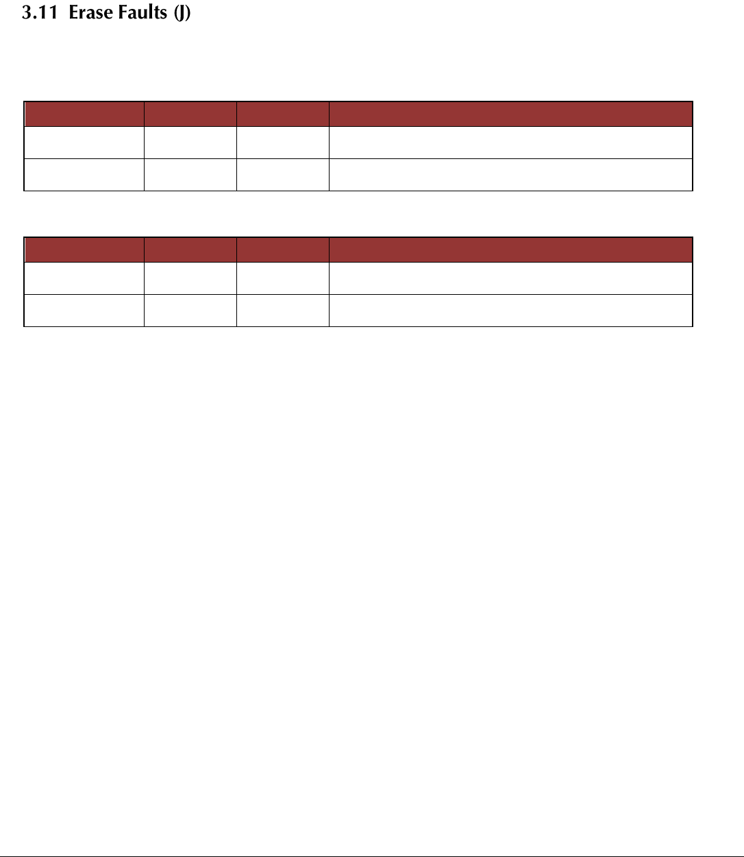
Used by the host controller to clear any existing fault indicators.
Sent by Host:
Data Element
Base Type
Instances
Description
Length
USHORT
1
Number of bytes to follow including checksum. Always
43for this message.
Command
UCHAR
1
Single ASCII character ‘J’ for Erase Faults.
Sent by RF Module:
Data Element
Base Type
Instances
Description
Length
USHORT
1
Number of bytes to follow including checksum. Always 3
for this message.
Command
UCHAR
1
Single ASCII character ‘j’ for Erase Faults acknowledge.
Page 21 of 31
Copyright © 2000-2013, Global Traffic Technologies, LLC
4. Query Messages
Module Identity Query (D)
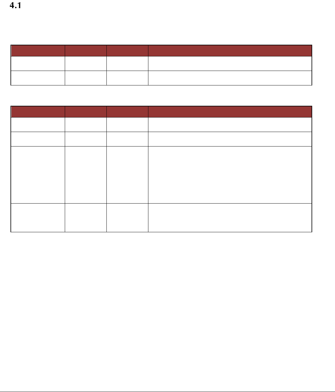
Used by the host controller to query the make/model and firmware revision of the unit.
Sent by Host:
Data Element
Base Type
Instances
Description
Length
USHORT
1
Number of bytes to follow including checksum. Always 3
for this message.
Command
UCHAR
1
Single ASCII character ‘D’ for Query Identity.
Sent by RF Module:
Data Element
Base Type
Instances
Description
Length
USHORT
1
Number of bytes to follow including checksum. Always 22
for this message.
Command
UCHAR
1
Single ASCII character ‘d’ for Identity acknowledge.
Serial Number
UCHAR[10]
1
Format is: RMssssssss where
RM denotes RF module and
ssssssss is the sequence number as labeled on the
radio board.
Refer to GTT Serial Number Format specification 79-
1000-0205-0
Firmware
Revision
UCHAR[9]
1
ASCII string representing the revision string.
Format is: XX.XX .XXX Leading zeros to be supplied if
single digit version number.
Page 22 of 31
Copyright © 2000-2013, Global Traffic Technologies, LLC
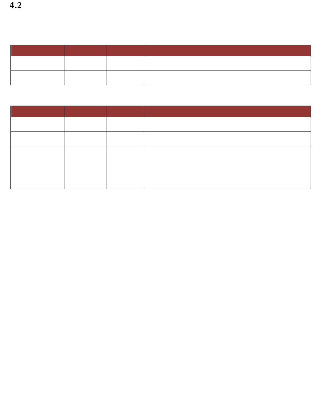
Mode Query (Q)
Used by the host controller to query the current operating mode of the unit.
Sent by Host:
Data Element
Base Type
Instances
Description
Length
USHORT
1
Number of bytes to follow including checksum. Always 3
for this message.
Command
UCHAR
1
Single ASCII character ‘Q’ for query mode.
Sent by RF Module:
Data Element
Base Type
Instances
Description
Length
USHORT
1
Number of bytes to follow including checksum. Always 4
for this message.
Command
UCHAR
1
Single ASCII character ‘q’ for Mode Acknowledge
Current Mode
UCHAR
1
Values are :
0 – Offline Mode
1 – Online Mode
2 – Transmit Test Mode
3 – Programming
4 – Broken Mode
Page 23 of 31
Copyright © 2000-2013, Global Traffic Technologies, LLC
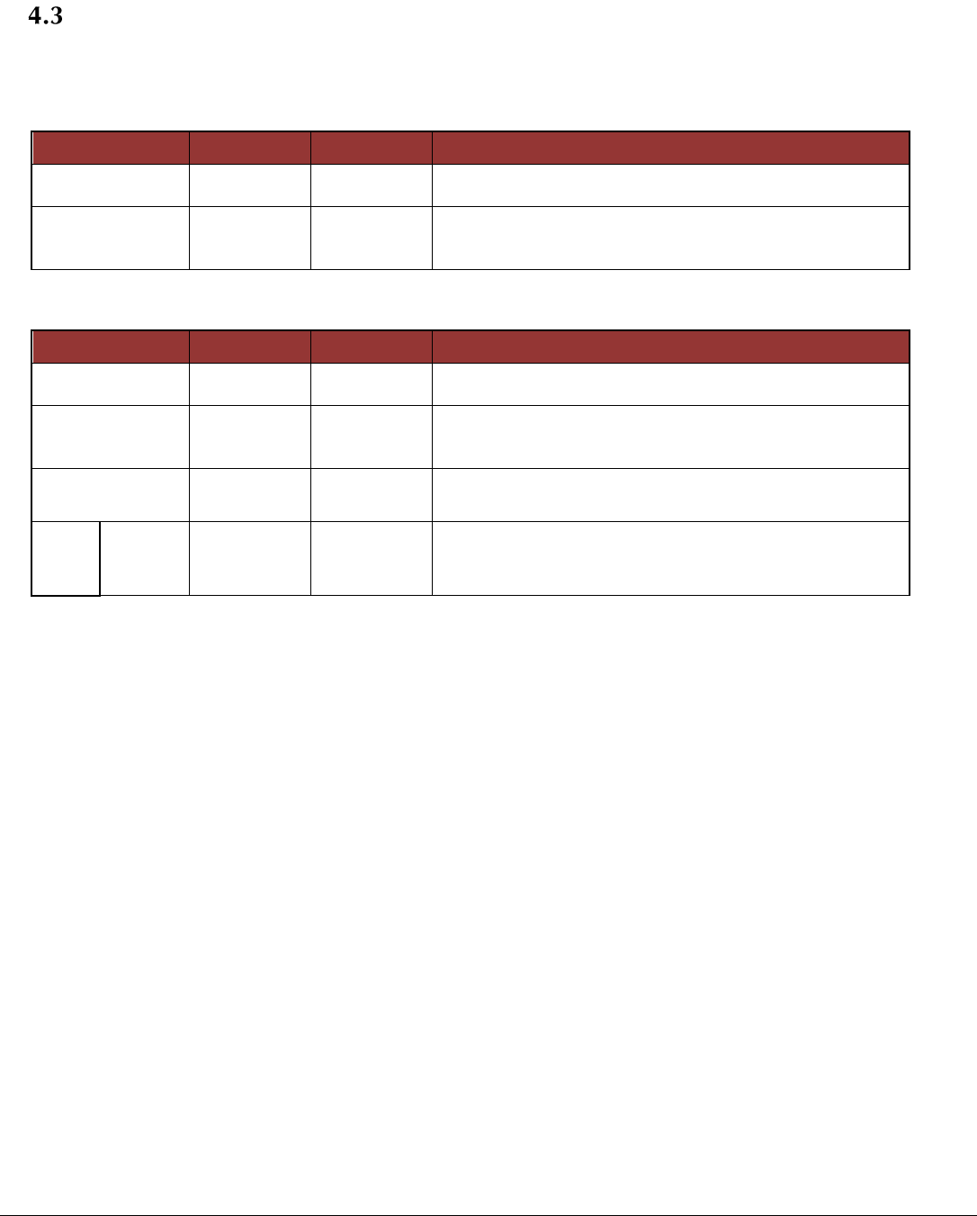
Framing Configuration Query (C)
Used by the host controller to query the current framing configuration of the unit.
Sent by Host:
Data Element
Base Type
Instances
Description
Length
USHORT
1
Number of bytes to follow including checksum. Always
3for this message.
Command
UCHAR
1
Single ASCII character ‘C’ for Query Framing
Configuration.
Sent by RF Module:
Data Element
Base Type
Instances
Description
Length
USHORT
1
Number of bytes to follow including checksum. Value is 4
+ (Number of slots * 2).
Command
UCHAR
1
Single ASCII character ‘c’ for Framing Configuration
acknowledge.
Number of
slots/hop
UCHAR
1
Number of slots to follow. Maximum of 255 slots. Default
is 186.
For
each
slot
Slot
Size
USHORT
1
Number of bytes in this slot. Maximum size is dictated by
the number of slots. Total number of bytes sent per frame
cannot exceed 16,000.
Page 24 of 31
Copyright © 2000-2013, Global Traffic Technologies, LLC
Hop Table Configuration Query (A)
Used by the host controller to query the Hop Table Configuration of the unit.
Sent by Host:
Data Element
Base Type
Instances
Description
Length
USHORT
1
Number of bytes to follow including checksum. Always 3
for this message.
Command
UCHAR
1
Single ASCII character ‘A’ for query Hop Table
Configuration.
Sent by RF Module:
Data Element
Base
Type
Instances
Description
Length
USHORT
1
Number of bytes to follow including checksum. Value is
5 + (number of rows * number of columns)
Command
UCHAR
1
Single ASCII character ‘a’ for Hop Table Configuration
acknowledge.
Number of rows
UCHAR
1
Number of seconds before repeating. Maximum of 25 rows.
Default is 25.
Number of columns
UCHAR
1
Number of frequency changes per second. Maximum
of 5 columns. Default is 3.
Note: rows * columns MUST be less than or equal to
75.
For
each
row
Channel 1
UCHAR
1
Receive channel for 1st hop in this second.
Channel 2
UCHAR
1
Receive channel for 2nd hop second.
Channel 3
UCHAR
1
Receive channel for 3rd hop in this second.
Channel n
UCHAR
1
Receive channel for nth hop in this second.
Page 25 of 31
Copyright © 2000-2013, Global Traffic Technologies, LLC
Broken Mode (B)
Used by the Host to query the reasons behind a Broken Mode report.
Sent by Host:
Data Element
Base Type
Instances
Description
Length
USHORT
1
Number of bytes to follow including checksum. Always 3
for this message.
Command
UCHAR
1
Single ASCII character ‘‘B’ for Query Broken Mode
Report.
Sent by RF Module:
Data
Element
Base Type
Instances
Description
Length
USHORT
1
Number of bytes to follow including checksum. Value is
4 + Number of failures)
Command
UCHAR
1
Single ASCII character ‘b’ for Broken Mode Report.
Number of
Failures
UCHAR
1
Count of failure codes to follow.
Failure
UCHAR
Number of
failures
Active failure indications.
1 – No 1 PPS detected
2 – VSWR fault

Page 26 of 31
Copyright © 2000-2013, Global Traffic Technologies, LLC
5. Hardware Interface
The following table provides the signal interface to the 20 pin interface connector
Pin Number
Signal Name
Description
1
GND
Signal/Power Ground
2
5V
5VDC Input
3
NC
4
NC
5
RXD
UART Receive Data Input
6
TXD
UART Transmit Data Output
7
J4.7
General Purpose Input/Output
8
GPIO2
General Purpose Input/Output 2
9
RESET
Reset Input – Active High
10
STATUS
Status Output
11
BOOT
Boot Mode Select – Active High
12
1PPS
1 Pulse Per Second Input
13
GND
Signal/Power Ground
14
3.3V
3.3VDC Input
15
NC
16
NC
17
GPIO4
General Purpose Input/Output 4
18
GPIO2
General Purpose Input/Output 2
19
GPIO3
General Purpose Input/Output 3
20
GPIO1
General Purpose Input/Output 1

Page 27 of 31
Copyright © 2000-2013, Global Traffic Technologies, LLC
6. Agency Statements
FCC Statements
Compliance Statement (Part 15.19)
This device complies with Part 15 of the FCC Rules.
Operation is subject to the following two conditions:
1. This device may not cause harmful interference, and
2. This device must accept any interference received, including interference that may cause undesired operation.
Warning (Part 15.21)
Changes or modifications not expressly approved by the party responsible for compliance could void the user’s authority to operate the
equipment.
FCC Interference Statement (Part 15.105 (b)
This equipment has been tested and found to comply with the limits for a Class B digital device, pursuant to Part 15 of the FCC Rules.
These limits are designed to provide reasonable protection against harmful interference in a residential installation. This equipment
generates uses and can radiate radio frequency energy and, if not installed and used in accordance with the instructions, may cause
harmful interference to radio communications. However, there is no guarantee that interference will not occur in a particular installation.
If this equipment does cause harmful interference to radio or television reception, which can be determined by turning the equipment
off and on, the user is encouraged to try to correct the interference by one of the following measures:
- Reorient or relocate the receiving antenna.
- Increase the separation between the equipment and receiver.
- Connect the equipment into an outlet on a circuit different from that
to which the receiver is connected.
- Consult the dealer or an experienced radio/TV technician for help.
RF Exposure (OET Bulletin 65)
To comply with FCC/IC RF exposure requirements for mobile transmitting devices, this transmitter should only be used or
installed at locations where there is at least 20cm separation distance between the antenna and all persons.
To comply with FCC/IC RF exposure limits for general population / uncontrolled exposure, the antenna(s)
used for this transmitter must be installed to provide a separation distance of at least 20 cm from all persons
and must not be co-located or operating in conjunction with any other antenna or transmitter.

Page 28 of 31
Copyright © 2000-2013, Global Traffic Technologies, LLC
Industry Canada Statements
Section 7.1.2 of RSS-GEN
Under Industry Canada regulations, this radio transmitter may only operate using an antenna of a type and maximum (or
lesser) gain approved for the transmitter by Industry Canada. To reduce potential radio interference to other users, the
antenna type and its gain should be so chosen that the equivalent isotropically radiated power (e.i.r.p.) is not more than
that necessary for successful communication.
User manuals for transmitters equipped with detachable antennas shall also contain the following notice in a
conspicuous location:
This radio transmitter IC7275A-OPTICOM3 has been approved by Industry Canada to operate with the antenna types
listed
below with the maximum permissible gain and required antenna impedance for each antenna
type indicated. Antenna types not included in this list, having a gain greater than the maximum
gain indicated for that type, are strictly prohibited for use with this device.
This device has been designed to operate with the antenna(s) listed below, and having a maximum gain of 3.5 dB.
Antennas not included in this list or having a gain greater than 3.5 dB are strictly prohibited for use with this device. The
required antenna impedance is 50 ohms.
List of all Antennas Acceptable for use with the Transmitter
Laird # MAF94192
HOW TSEN # S-001-1
Mobile Mark # DM2-2400/1575
Section 7.1.3 of RSS-GEN
This Device complies with Industry Canada License-exempt RSS standard(s). Operation is subject to the following two
conditions: 1) this device may not cause interference, and 2) this device must accept any interference, including
interference that may cause undesired operation of the device.
Industrie Canada déclarations
Section 7.1.2 du RSS-GEN
Aux termes des règlements de l'industrie du Canada, cet émetteur radio peut fonctionner uniquement à l'aide d'une
antenne d'un type et un maximum (ou moins) de gain approuvé pour l'émetteur par Industrie Canada. Pour réduire le
risque d'interférence aux autres utilisateurs, le type d'antenne et son gain doivent être choisis afin que la puissance
isotrope rayonnée équivalente (e.i.r.p.) ne dépasse pas ce qui est nécessaire pour une communication réussie.

Page 29 of 31
Copyright © 2000-2013, Global Traffic Technologies, LLC
Les manuels d'utilisation pour des émetteurs équipés des antennes détachables contiendront également la
notification suivante dans un endroit remarquable
Cet émetteur radio IC7275A-OPTICOM3 a été approuvé par Industrie Canada pour fonctionner avec les types d'antennes
énumérées ci-dessous avec le gain maximal admissible et l'impédance d'antenne requise pour chaque antenne type
indiqué. Types d'antenne non inclus dans cette liste, ayant un gain supérieur au maximum gagner indiqué pour ce type,
sont strictement interdites pour une utilisation avec cet appareil.
Ce dispositif a été conçu pour fonctionner avec l'antenne (s) ci-dessous, et ayant un gain maximum de 3,5 dB. Antennes
pas inclus dans cette liste ou ayant un gain supérieur à 3,5 dB sont strictement interdites pour une utilisation avec cet
appareil. L'impédance d'antenne requise est de 50 ohms.
Liste de toutes les antennes acceptables pour une utilisation avec l'émetteur
Laird # MAF94192
HOW TSEN # S-001-1
Mobile Mark # DM2-2400/1575
Section 7.1.3 du RSS-GEN
Cet appareil est conforme avec Industrie Canada norme exempte de licence RSS (s). Son fonctionnement est soumis aux
deux conditions suivantes: 1) cette appareil peut ne pas causer l'interférence et 2) cet appareil doit accepter toute
interférence, y compris les interférences qui peuvent causer un mauvais fonctionnement de l'appareil.
OEM Responsibilities to comply with FCC and Industry Canada Regulations
The OPTICOMGPS3 Module has been certified for integration into products only by OEM integrators under the
following conditions:
1. The antenna(s) must be installed such that a minimum separation distance of 20cm is maintained
between the radiator (antenna) and all persons at all times.
2. The transmitter module must not be co-located or operating in conjunction with any other antenna or
transmitter.
As long as the two conditions above are met, further transmitter testing will not be required. However, the OEM
integrator is still responsible for testing their end-product for any additional compliance requirements required
with this module installed (for example, digital device emissions, PC peripheral requirements, etc.).
IMPORTANT NOTE: In the event that these conditions cannot be met (for certain configurations or co-location with
another transmitter), then the FCC and Industry Canada authorizations are no longer considered valid and the FCC ID
and IC Certification Number cannot be used on the final product. In these circumstances, the OEM integrator will be

Page 30 of 31
Copyright © 2000-2013, Global Traffic Technologies, LLC
responsible for re-evaluating the end product (including the transmitter) and obtaining a separate FCC and Industry
Canada authorization.
End Product Labeling
The OPTICOMGPS3 Module is labeled with its own FCC ID and IC Certification Number. If the FCC ID and IC
Certification Number are not visible when the module is installed inside another device, then the outside of the device
into which the module is installed must also display a label referring to the enclosed module. In that case, the final
end product must be labeled in a visible area with the following:
“Contains Transmitter Module FCC ID: VJB-OPTICOMGPS3”
“Contains Transmitter Module IC: 7275A-OPTICOM3”
or
“Contains FCC ID: VJB-OPTICOMGPS3”
“Contains IC: 7275A-OPTICOM3”
The OEM of the OPTICOMGPS3 Module must only use the approved antenna(s) listed above, which have been certified with
this module.
The OEM integrator has to be aware not to provide information to the end user regarding how to install or remove this RF
module or change RF related parameters in the user manual of the end product.
To comply with FCC and Industry Canada RF radiation exposure limits for general population, the antenna(s)
used for this transmitter must be installed such that a minimum separation distance of 20cm is maintained
between the radiator (antenna) and all persons at all times and must not be co-located or operating in
conjunction with any other antenna or transmitter.

Page 31 of 31
Copyright © 2000-2013, Global Traffic Technologies, LLC
7. Revision History
Date
Revision
Status
Description of Changes
March 15, 2012
A
Active
Initial release
November 21, 2013
B
Active
Changed Opticom™ to Opticom®
Updated footer Copyright © 2000-2013
Replaced OPTICOM2 with OPTICOM3 (4 instances)
Replaced OPTICOMGPS2 with OPTICOMGPS3 (5
instances)