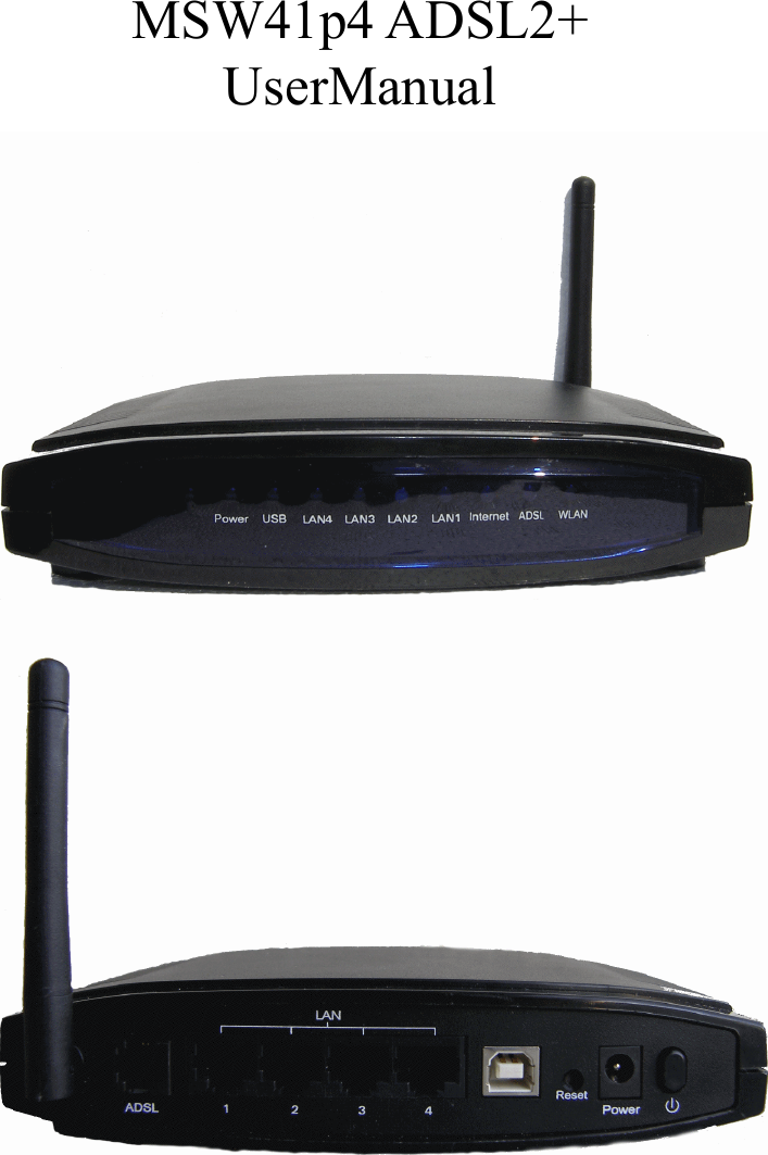
Global411 Internet Services QA-ZBQI-W0NKP4 4 PORT ADSL2+ DSL GATEWAY/ROUTER/WIFI User Manual MSW41p4

Global411 Internet Services, LLC 4 PORT ADSL2+ DSL GATEWAY/ROUTER/WIFI MSW41p4

Contents

user manual

MSW41p4 ADSL2+ UserManual
1. Overview 1.1 About MSW41p4  MSW41p4 is a high quality multifunction internet access device offering ADSL, WiFi, USB device and LAN switch. The advanced QoS ensures high quality in the bandwidth-consuming services like IPTV, IP Camera and so on. It simply enables the user to build their wireless network upon LAN network and play a role in the overall management and coordination to provide users with convenience. 1.2 Advanced features and benefits 1. Support IEEE 802.11b/g WiFi, simply enables user to build a wireless network upon LAN network, and access internet through high speed ADSL router. 2. Support ADSL2+(maximum downstream 24Mbps and upstream 1Mpbs) 3. Support Advanced QoS (Quality of Service) feature. It ensures high quality with smooth  connection  for  any  type  of  data.  Particularly  latency-sensitive  and bandwidth-consuming applications such as IPTV etc. 4. Support  TR-069  remote  management:  configuration,  software  upgrade, troubleshooting etc.    1.3 Features and Technical Specifications ADSL  ANSI T1.413 issue 2 compliant  ITU-T G.992.1(G.DMT) compliant: Up to 8Mbps downstream and 896Kbps upstream    ITU-T G.992(G.lite) compliant: supports splitter-less implementation.  ITU G.992.3/4(ADSL2) compliant: enhanced performance on long lines   ITU  G.992.5(ADSL2+)  compliant:(up  to  24Mbps  downstream  and  1Mbps upstream)  PVCs:16  PVC supported model:  PPPoE/PPPoA/DHCP/Static/Bridge   IP  NAT/NAPT  Firewall,support SPI(stateful packet inspection)    DHCP server
 Port forwarding(support DMZ)  IP filtering,bridge filtering,Web filtering  Static routing  Dynamic routing(RIP and RIP2)  SNTP  VPN, support PPTP and IPSec VPN  Multicast:IGMP Proxy/IGMP Snooping  ALG  UPnP Ethernet  IEEE 802.3  4 port Ethernet: 10/100M Ethernet Auto MDI-X WiFi  IEEE 802.11b/g compliance  Security:WEP 64/124/256 bits、WPA/WPA2  WMM QoS    WDS wireless AP  Multiple SSID configuration  RF power : 20dBm    Antenna type : Outside Omni-directional Antenna  RF on/off  ACS(Automatic channel selection)  MAC address white-black filter Operation and Management (OAM)  Support Web based management  Support SNMP v1/v2/v3    UPnP  Telnet/SSH  Software upgrade through HTTP/TFTP/FTP  TR069(CPE management through WAN interface) QoS  Support input rate limit  IP QoS:base on source IP address, source and destination port, protocol and DSCP    ATM QoS:support CBR,UBR,nrt-VBR,rt-VBR USB  Support one USB device
2. Specification   2.1 Interface introduction   2.1.1 Interface & Indicator Light Introduction   Item  Label  Description Indicator Light Power ON:MODEM power on OFF:MODEM power off USB ON: MODEM linked to PC via USB interface Flash: MODEM sending/receiving data via USB interface OFF:No connection LAN1- LAN4 ON:Ethernet is connected   BLINK:Ethernet Traffic flows OFF:Ethernet is disconnected Internet ON: in Router mode and ADSL connected, can transmit IP packets   OFF: in Bridge mode or ADSL disconnected Flash: Data transmitting via LAN interface ADSL BLINK Slowly:MODEM idle BLINK  Quickly:MODEM  training,  but  not synchronized ON:MODEM synchronized to the DSLAM WLAN OFF:WLAN is disable ON:WLAN is enable BLINK: WLAN Traffic flows Interface Introduction Antenna  Sending & receiving wireless signal ADSL  Connect to the ADSL line or the MODEM port of Splitter
LAN1- LAN4  LAN interface for connecting to computer USB  Connect to PC USB port Reset  Restore to factory default settings Power  For 12V DC power adaptor  Power switch  Notice: the LAN port support 10M/100M, AUTO MDI-X. 2.1.2 Interface of splitter  Label  Introduction LINE  Connect to the ADSL line MODEM  Connect to ‘DSL’ port of the MODEM PHONE  Connect to the phone    2.1.3 Package checking Router is shipped with the following items:  Item  Quantity  Remark Power Adapter  1   Phone line  2   RJ45 Network Line    1   MODEM  1   Splitter  1              2.2 Hardware Connection Introduction: 1、 Use a  telephone cord  to  connect the  LINE port  of the  splitter  with the  RJ-11 port  (the phone jack) on the wall. 2、 Use another telephone cord to connect the ADSL port of the splitter with the LINE port of the ADSL Modem. 3、 Use  another  telephone  cord  to  connect  the  telephone  set  with  the  PHONE  port  of  the splitter. 4、 Connect Ethernet port of the ADSL MODEM with 10/100BASE-T port of the computer
using the network cable that comes with the modem. 5、 Plug in the power cord, and turn on the power.  If you do not want Internet services and telephone voice services simultaneously, please just connect the LINE port of the ADSL Modem with the RJ-11 port (the phone jack) on the wall using a telephone cord. In this case, the splitter is not necessary.  2.3 Layout  Notice::::  PC connects to ADSL LAN port for internet access;  Laptop (integrate WiFi) can access internet via WiFi wireless connection;  STB (set top box) connect to LAN port for IPTV application.    Wireless ADSL router provides 4 Ethernet cable ports LAN0~LAN3 in support of 10M/100M,  AUTO  MDI-X,  user  can  connect  4  PCs  via  4  cable  lines,  no  extra HUB or SWITCH is needed. Warning::::If  the  phone  line  is  previously  in-bridged  with  other  phones,  please  make  sure every phone set is connected behind the splitter or installed a splitter before every phone set, otherwise interruptions will be caused on line and ADSL connection may be unstable.
3. Configuration Guide 3.1 Default Configuration ADSL  MODEM  has  pre-configured  with  the  VCI/VPI  which  is  in  common  use,  mode  is bridge encapsulation. For bridge mode, no need to configure any more parameter. 3.2 Computer Configuration The  default  IP  address  for  ADSL  MODEM  is:  192.168.2.1;  The  Subnet  Mask  is :255.255.255.0. Users can configure ADSL MODEM through an Internet browser. ADSL MODEM can  be  used  as  gateway  and  DNS  server;  users  need  to  set  the  computer’s  TCP/IP  protocol  as follow: 1、 Set  the  computer  IP  address  at  same  IP  range  of  ADSL  MODEM,  such  as  set  the  IP address of the network card to one of the “192.168.2.2” 2、 Set the computer’s gateway the same IP address as the ADSL Modem’s. 3、 Set computer’s DNS server the same as ADSL Modem’s IP address or that of an effective DNS server. 3.2.1 Log In     Power on to start the device, making sure your computer can PING via LAN port of ADSL (the  factory  default  IP  is  192.168.2.1),  then  run  IE.  Inputting  http://192.168.2.1  in  the  address column, press ENTER, and authentication interface will pop up as below:    The default username and password is admin for web log-on. Press ENTER or click on ‘OK’
to enter into ADSL main page to perform configuration after entering the accurate user name and password in the dialog box. Warning: Please be sure IP of the computer network card is in the same IP range as ADSL LAN  port  before  trying  to  log  on  (ex:  192.168.2.2  and  192.168.2.1  are  in  the  same  IP  range). Please  follow  the  steps  below  to  enter:  IE---Tool---Internet  Option---Connection---LAN Setup---Proxy server, disable the function ‘Proxy for LAN’, that disable the proxy server. If log on successfully, the main page will be displayed as follows:   3.2.2 Introduction for the Structure of WEB Interface Web interface consists of five menu options. Each option is for configuring certain part of the whole  system. User  can perform  the configuration  of each  part  individually in  accordance  with their own needs. 1) Device Info Here  include  “Summary”,  “WAN”  information,  “Statistic”  information, “Route” information, “ARP” information etc.   2) Advanced setup Here  include  “WAN  setup”,  “LAN  setup”,  “Security”,  “Route”,  “DSL”,  “Print Server”, “IPSec” etc. 3) Wireless Here  include  “Basic”,  “Security”,  “MAC  Filter”,  “Wireless  Bridge”,  “Advanced”, “Station Info” etc. 4) Diagnostics
For check connection and test result 5) Management Here  include  “Settings”,  “System  Log”,  “TR-069  Client”,  “Internet  Time”, “FTP”, “Access Control”, “Update Software” “Save/Reboot” etc. 3.2.3 Save / Reboot If  we  change  some setting  and  want  to  keep it  after  reboot.  You  can  click  “Save/Reboot” after change the setting in each page. You also can change all setting and go to “Management”→ “Save/Reboot” to save all. 3.2.4 WAN Configuration If the configuration is bridge encapsulation, there is no need to configure any more parameters. Only need to use the third party dial-up software to connect the Internet.   This router completely supports:PPPoA、PPPoE、MER、IPoA、Bridging. For detail configuration information, please check the following configuration guide. 3.2.4.1 Configuration Guide Choose “Advanced Setup”→ “WAN”, enter Wide Area Network (WAN) Setup interface.
1) Click “Add”, enter the configure guide. Notice: Default we can have eight connections. The Max number of connections is 16.  2) The value for VPI/VCI is assigned by your ISP. After inputting the PVC value, press “Next” into “Connection type”.  The Modem supports five ADSL protocol modes. Choose the protocol which is appointed by ISP  and  PVC  encapsulation,  click  “Next”  enter  to  the  protocol  configure.  Below,  we introduce the configuration of the five protocol modes. • PPP over ATM (PPPoA)                                      • PPP over Ethernet (PPPoE)
• MAC Encapsulated Routing (MER)                    • IP over ATM (IPoA) • Bridging  3) Some  connection  lines  need  to  confirm  the  LLC  or  VC,  if  you  can’t  confirm, please don’t modify the default value or ask your ISP. 3.2.4.2 RFC1483 Bridge Configuration Select the Bridging mode. Then Press to  specify the Service Name, and select  the “Enable Bridge Service”.  Press “Next” to  enter into “WAN configuration”, click “save” to save configuration, if  you need to modify the parameter, click “back”.  Notice::::When you use bridge mode, please close “DHCP SERVER”
 3.2.4.3 PPPoE Configuration PPPoE is also known as RFC 2516. It is a method of encapsulating PPP packets over Ethernet. PPPoA is also known as RFC2364 and named as Peer to Peer Protocol over ATM. As PPPoE, it also has all the features of PPP. Although it’s based on ATM protocol, the setting of all the other parameters is similar with PPPoE. So we only introduce PPPoE in detail here.   Select PPP over Ethernet (PPPoE), press “Next” entering the configuring interface.   PPP Account: Your account from ISP to access Internet.  Password: Input the password assigned by your ISP.  PPPoE server name: Server name of network ISP. No need to set.  Authentication Mode: Authentication mode of network ISP. Default is AUTO. Press “Next” when configuration is finished. Notice that PPPoE mode does not work until the modem is reset.
3.2.4.4 Static Address   Select Mac Encapsulation Routing (MER), press “Next” and the configuration can be queried from your ISP. Click “Save/Apply” when configuration is finished.  3.2.5 Wireless Configuration Press  “Wireless”  on  the  top  of  web  pages  to  enter  wireless  section.    You  can  select  to configure wireless setup, security and management. 3.2.5.1 Wireless Setup Click “Basic” on the left menu to setup basic wireless parameters. In default, check “Enable Wireless” box to launch wireless AP.  SSID (Service Set Identifier): The mobile users cannot access WLAN until setting their SSID as the same value of the wireless ADSL. The SSID value of the ADSL is “MSW41p4”  Hidden Access Point: If checked, wireless station will no see SSID of the ADSL.
Click “Save/Apply” when configuration is finished. 3.2.5.2 Wireless Security Press “Security” on the left menu to construct wireless security. You can select to configure WEP encryption, Shared, 802.1x, WPA, and WPA2 authentication.  WEP Encryption    DEFAULT password “apmsw41p4” Select “Enabled” of the WEP encryption list. You can enter WEP encryption page. Encryption Strength: Key length: 128bits or 64bits. Network Key 1-4: Up to four keys that are in form of hex digitals could be set. Mobile users can’t access the AP if they haven’t set the same key as AP. For 64bits and 128bits keys, you should input 10 and 26 hexadecimal digitals or 5 and 13 ASCII characters respectively. Every two  digitals  should  be  comparted  with  others  by  a  space  character.  For  example: “7890ABCDEF” (hexadecimal digitals) or “QWERT” (ASCII characters) for a key length of 64bits.  802.1x Authentication Select “802.1x” to enter 802.1x authentication page.   The 802.1x authentication needs a Radius server in LAN. In this page, you can input Radius server IP address, port number and secret key.
3.2.5.3 Wireless Mac Filter In fact, the Access List function is just like MAC address filtering and selected to permit or forbid access of wireless station with specified MAC address. Method: select “Allow” or “Deny” mode, and click “Add” button, and input MAC address which you want to allow or deny.   Notice: You only can select one either allow mode or deny mode not both. 4. Other Configuration 4.1 LAN Configuration Configuration of Modem’s IP address and password.
4.1.1 Configuration of Modem’s IP Address As a network device, ADSL Modem has its own IP address and MAC address. The factory sets the MODEM, at a default IP address of 192.168.2.1 and subnet mask of 255.255.255.0. The user can configure these addresses through the “LAN” on “Configuration” like this: For  example,  change  IP  address  to  “192.168.2.1”.  Click  “LAN”,  input  “IP  address”: 192.168.2.2, then “subnet mask”: 255.255.255.0, Press “Save” when configuration is finished.  Notice::::If you change IP address, it will take effect after you reboot the modem. You must use the new IP address to login.   4.1.2 DHCP Configuration  Click““““LAN  ””””  Click“DHCP server””””;  Define the “Start IP address” and the “End IP address” of DHCP server (for example, from 192.168.2.2 to 192.168.2.254).    Input the value of lease (Measured by the second, 0 indicates permanently valid).   Enable  DHCP  server,  computer  will  set  the  IP  Address  of  network  card  with  one  of  the address 192.168.2.1  ~  192.168.2.254 (Excluding 192.168.2.1). Notice::::When you use the DHCP Server, please pay attention to having multi-DHCP Server in one LAN. 4.2 Password Configuration When you configure ADSL MODEM through an Internet browser, the system requires user
name  and  password  to  validate  access  permission.  The  factory  sets  the  modem  at  a  default username of “admin” and the password of “admin”. Choose “Management” -> “Access Control” -> “Passwords”, you can choose the username and change the password.    Attention:  please  remember the password after change,  otherwise you need to reset the device to change configuration after saving setting.    5. Troubleshooting 5.1 Unable to Access Internet 5.1.1 Check the Line and the Device 1、 Check the  indicator of power supply  is on, if  not, Make  sure  the  connection of  power supply is correct; Make sure the output of power supply is correct; Make sure the switch of power supply is turned on; 2、 Check the indicator of PC is on, if not, Make sure the connection of cable and network adapter; Make sure that the correct cable is used; 3、 Check the LINK LED to see if it is twinkling. If no fast twinkling is observed within 3 minutes,  please  check  whether  phone  line  has  been  correctly  placed;  whether  ADSL separator is correctly used. If multiple extensions have been installed, make sure that the separator  is  installed  prior  to  the  junction  box  of  phone  line.  If  the  above  items  are confirmed  and  still  no  fast  twinkling  of  WAN  LED  is observed,  call  the  ISP  to query whether ADSL service has been provided on your line; 4、 Check the LINK LED to see whether it is unable to change status from fast twinkling to always light, or whether it changes status to fast twinkling after sometime of always light.
If  these phenomena  occur  constantly,  please  contact  your  ISP  with a demand  to  check lines and signal quality;  If there is no problem in the above items, the line and the device shall be working. Problems may come from your computer configuration or device configuration. 5.1.2 CHECK YOUR CONFIGURATION We  explain  here  the  configuration  of  PPPOE  using  Windows  XP  operation  system  as  an example. For other operation systems the process is similar. 1、 Enter  the  device  manager  to  check  if  Ethernet  adapter  is  correctly  installed.  If  any problem exists, please re-installed it; 2、 Check the configuration of Ethernet adapter in PC. Try to manually set IP address that is in band 192.168.2.X without conflict. See 3.2; 3、 Try to run command “ping 192.168.2.1” on command line mode. If the response returns “time out”, please check Ethernet connection and IP settings; 4、 If this modem is reachable, try to run ping with a known outer IP, e.g. the DNS server IP of www.yahoo.com: “ping 209.131.36.158”.  If ping is reachable, there shall be no problems in the modem. Please see step 5;  If ping is not reachable, see step 6 and check if the configuration is correct.  5、 Please try to ping a certain outer URL, e.g. “ping www.google.com”.  If  ping  is  reachable,  there  shall  be  no  problems  in  the  network  settings.  Please check the settings of the PC terminal, e.g. whether the security level is too high, or whether anti-virus firewall is installed;  If ping is not reachable, check the DNS setting of Ethernet adapter. See 3.2.  Note 1:The precondition is that LAN settings in the modem has not been modified. Note 2:We usually start command line mode in Windows XP as follows: click on the “RUN” item of Windows Start Menu, input characters “cmd” in the input box popped up with an “Enter”. The window subsequently popped up is the command line window. Note 3:The returned values of ping command in the following format show the standard of “reachable”
  6,      If ping of the modem is reachable but ping of the outer fixed IP is unreachable, attention should  be  concentrated  upon  device  settings.  Please  enter  the  configuring  interface following the instructions in this manual. (1) Check  first  the  number  of  connections.  If  more  than  one  connection  exists,  for troubleshooting, delete unused  connections and  remain the one connection you  are using. (2) Check the connection to see whether correct “type” is selected. It’s normal to choose login  type  of  PPPoE.  When  you  use  PPPoE  to  login,  the  following  information should be provided: VPI and VCI, which can be queried from your ISP, user name and password. (3) Then make sure that “using NAT” and “default gateway” have been selected with a tick.  Check  whether  “connect  on  demand”  has  been  selected  with  a  tick.  If  it  is selected, the connection  is activated only when traffic to outer  networks arrives. If not  selected,  check  “keep connection”,  which should be  set to  0  if  you demand to keep connection  Make sure that the above parameters are saved after configuration. Internet is now available since the configuration is properly done.
FCC STATEMENT 1. This device complies with Part 15 of the FCC Rules. Operation is subject to the following two conditions: (1) This device may not cause harmful interference. (2) This device must accept any interference received, including interference that may cause undesired operation. 2. Changes or modifications not expressly approved by the party responsible for compliance could void the user's authority to operate the equipment.  NOTE: This equipment has been tested and found to comply with the limits for a Class B digital device, pursuant to Part 15 of the FCC Rules. These limits are designed to provide reasonable protection against harmful interference in a residential installation. This equipment generates uses and can radiate radio frequency energy and, if not installed and used in accordance with the instructions, may cause harmful interference to radio communications. However, there is no guarantee that interference will not occur in a particular installation. If this equipment does cause harmful interference to radio or television reception, which can be determined by turning the equipment off and on, the user is encouraged to try to correct the interference by one or more of the following measures:    Reorient or relocate the receiving antenna.    Increase the separation between the equipment and receiver.    Connect the equipment into an outlet on a circuit different from that to which the receiver is connected.    Consult the dealer or an experienced radio/TV technician for help.   FCC Radiation Exposure Statement This equipment complies with FCC radiation exposure limits set forth for an uncontrolled environment. This equipment should be installed and operated with minimum distance 20cm between the radiator & your body

Navigation menu