GlobalSat WorldCom LM513 LoRa Module User Manual
GlobalSat WorldCom Corporation LoRa Module Users Manual
Users Manual.pdf
1
Product Specifications
Dual-mode
LoRa® Wireless
Module
LM-513H
VER: 1.0A
GlobalSat WorldCom Corporation
16F., No. 186, Jian 1st Rd, Zhonghe Dist.,
New Taipei City 23553, Taiwan
Tel: 886.2.8226.3799/ Fax: 886.2.8226.3899
lora@globalsat.com.tw
www.globalsat.com.tw
USGlobalSat Incorporated
14740 Yorba Court Chino, CA 91710
Tel: 888.323.8720 / Fax: 909.597.8532
sales@usglobalsat.com
www.usglobalsat.com

1
Product Description
The GlobalSat LM-513H is a pin type RF module that based on LoRa® technology
which provides long-range, low data rate IoT connectivity to sensors, electronic meter
reading, geolocation devices, industrial monitoring and control, home and building
automation, long range irrigation systems, and all kinds of IoT/ M2M equipments. It
can works as the end-node devices in the LoRaWANTM infrastructure or in GlobalSat
proprietary ecosystem (MOST-Link).
Product Feature
Built-in standard LoRaWAN™ FW and proprietary MOST-Link FW in the
same module
Share same PCB/ device design for both LoRaWAN™ and private RF
data communication
Ultra-high sensitive receiving ability by LoRa® spread spectrum
modulation technology
Long-distance transmission (1KM to 10KM)
Instant wake up over the air
LoRa®/ FSK/ GFSK/ OOK modulation, 2-way half –duplex communication,
strong anti-interfere
Maximal output power 100 mW (20 dBm), output power adjustable between
5-20 dBm
Easily use, auto exchange on communication & transceiver
Tuning free
Accord FCC,ETSI, TELEC standard

2
Hardware Specifications
Item
Content
LoRa® Module
GlobalSat Dual-mode LoRa® Module LM-533H
Frequency
863 ~ 870 MHz (EU)
902 ~ 928 MHz (US)
920 ~ 928 MHz (ROA)
Transmission Power
862 ~ 870 MHz (EU) @ 14 dBm
902 ~ 928 MHz (US) @ 20 dBm
920 ~ 928 MHz (ROA) @ 20 dBm
Transmission Media
UART
UART
Baud Rate : 57600 bps
Parity: 8N1
Operation Voltage
2.4 ~ 3.6V
Current Consumption
Receiving: 18.2 mA (Typical)
Transmitting: 125 mA (Typical)
Sleeping: 2 uA (Typical)
Transmission Distance
LoRaWANTM: 1 ~ 10 KM @ 980 bps
MOST-Link: 1 ~ 10 KM @ 0.81 Kbps
Receiving Sensitivity
LoRaWANTM: -132 dBm @ 980 bps
MOST-Link: -132 dBm @ 0.81 Kbps
Operation Temperature
-40 ~ 85°C
Humidity
5 ~ 95% (Non-condensing)
Dimension
30 x 18 ± 0.2 mm (PCBA)
Connector
PIN type, pitch 2.54 ± 0.1 mm
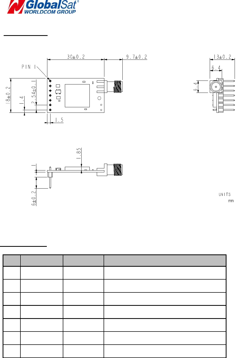
3
Product Size
Pin Definition
No
Pin
Definition
Description
1
GND
GND
Ground
2
VCC
Input
3.0 ~ 6.0 V
3
RXD
Input
UART input
4
TXD
Output
UART output
5
BZ
NC
No connection
6
P2
NC
No connection
7
P1
NC
No connection

4
LoRaWANTM Configuration
Activation of an end-device can be achieved in two ways, either via Over-The-Air
Activation (OTAA) when an end-device is deployed or reset, or via Activation By
Personalization (ABP) in which the two steps of end-device personalization and
activation are done as one step.
Over-the-Air Activation
For over-the-air activation, end-devices must follow a join procedure prior to
participating in data exchanges with the network server. An end-device has to
go through a new join procedure every time it has lost the session context
information. The join procedure requires the end-device to be personalized with
the following information before its starts the join procedure: a globally unique
end-device identifier (DevEUI), the application identifier (AppEUI), and an AES-
128 key (AppKey).
Activation by Personalization
Under certain circumstances, end-devices can be activated by personalization.
Activation by personalization directly ties an end-device to a specific network
by-passing the join request join accept procedure.
Activating an end-device by personalization means that the DevAddr and the
two session keys NwkSKey and AppSKey are directly stored into the end-
device instead of the DevEUI, AppEUI and the AppKey. The end-device is
equipped with the required information for participating in a specific LoRa
network when started. Each device should have a unique set of NwkSKey and
AppSKey. Compromising the keys of one device shouldn‘t compromise the
security of the communications of other devices.
Operation Mode
Bi-directional end-devices (Class A): End-devices of Class A allow for bi-
directional communications whereby each end-device's uplink transmission is
followed by two short downlink receive windows. The transmission slot
scheduled by the end-device is based on its own communication needs with a
small variation based on a random time basis (ALOHA-type of protocol). This
Class A operation is the lowest power end-device system for applications that
only require downlink communication from the server shortly after the end-
device has sent an uplink transmission. Downlink communications from the

5
server at any other time will have to wait until the next scheduled uplink.
Bi-directional end-devices with maximal receive slots (Class C): End-
devices of Class C have nearly continuously open receive windows, only
closed when transmitting.
MOST-Link Configuration
There are three operating modes in MOST-Link configuration state as below;
1. Normal mode
2. Wake-up mode
3. Power-saving mode
The different operation modes are switched by AT-command.
Mode 1: Normal mode
UART is opened. Wireless channel is opened. Penetrating transmission.
Mode 2: Wake-up mode
UART is opened. Wireless channel is opened. The only difference from normal
mode is that its preamble is longer than normal mode’s, so that it can make sure
the receiver could be waked in the power-saving mode.
Mode 3: Power-saving mode
UART is closed. The wireless channel is in power-saving mode. You can set up
an interval from 0.5 to 5 seconds to wake up in power-saving mode to check if
there is preamble. If the receiver receives preamble, it will open UART, and
wake MCU to process the received data and return data. After that, it will return
to the power-saving mode.
Note:
The receiver could be waked no matter it is in normal mode or wake-up mode or power-saving mode. The
receiver would automatically add the RSSI

6
Federal Communication Commission Interference Statement
This device complies with Part 15 of the FCC Rules. Operation is subject to the following two
conditions: (1) This device may not cause harmful interference, and (2) this device must accept
any interference received, including interference that may cause undesired operation.
This equipment has been tested and found to comply with the limits for a Class B digital device,
pursuant to Part 15 of the FCC Rules. These limits are designed to provide reasonable
protection against harmful interference in a residential installation. This equipment generates,
uses and can radiate radio frequency energy and, if not installed and used in accordance with
the instructions, may cause harmful interference to radio communications. However, there is no
guarantee that interference will not occur in a particular installation. If this equipment does
cause harmful interference to radio or television reception, which can be determined by turning
the equipment off and on, the user is encouraged to try to correct the interference by one of the
following measures:
- Reorient or relocate the receiving antenna.
- Increase the separation between the equipment and receiver.
- Connect the equipment into an outlet on a circuit different from that
to which the receiver is connected.
- Consult the dealer or an experienced radio/TV technician for help.
FCC Caution: Any changes or modifications not expressly approved by the party responsible for
compliance could void the user's authority to operate this equipment.
This transmitter must not be co-located or operating in conjunction with any other antenna
or transmitter.
FOR MOBILE DEVICE USAGE (>20cm/low power)
Radiation Exposure Statement:
This equipment complies with FCC radiation exposure limits set forth for an uncontrolled
environment. This equipment should be installed and operated with minimum distance 20cm
between the radiator & your body.
This device is intended only for OEM integrators under the following conditions:
1) The antenna must be installed such that 20 cm is maintained between the antenna and users.
2) The transmitter module may not be co-located with any other transmitter or antenna.
As long as 2 conditions above are met, further transmitter test will not be required. However, the
OEM integrator is still responsible for testing their end-product for any additional compliance
requirements required with this module installed
IMPORTANT NOTE: In the event that these conditions can not be met (for example certain
laptop configurations or co-location with another transmitter), then the FCC authorization is no
longer considered valid and the FCC ID can not be used on the final product. In these
circumstances, the OEM integrator will be responsible for re-evaluating the end product
(including the transmitter) and obtaining a separate FCC authorization.
End Product Labeling
FOR MOBILE DEVICE USAGE (>20cm/low power)
This transmitter module is authorized only for use in device where the antenna may be installed
such that 20 cm may be maintained between the antenna and users. The final end product must
be labeled in a visible area with the following: “Contains FCC ID:RID-LM513”. The grantee's
FCC ID can be used only when all FCC compliance requirements are met.
Manual Information To the End User
The OEM integrator has to be aware not to provide information to the end user regarding how to
install or remove this RF module in the user’s manual of the end product which integrates this
module. The end user manual shall include all required regulatory information/warning as show
in this manual.
The specifications are subject to change without notice. Copyright © 2018, GlobalSat WorldCom Group.