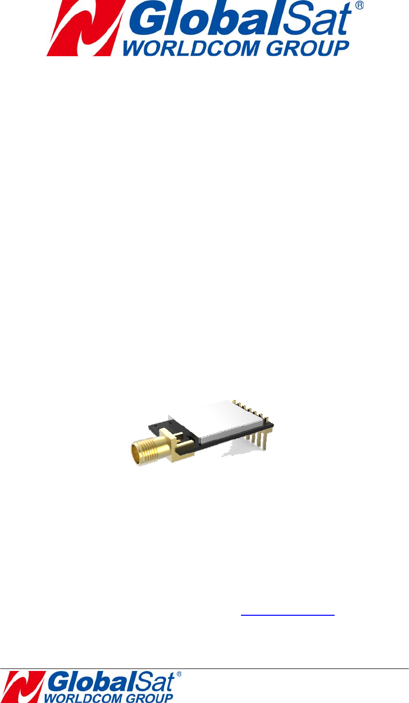
GlobalSat WorldCom LR101H LoRa Wireless Module User Manual
GlobalSat WorldCom Corporation LoRa Wireless Module Users Manual
Users Manual

LoRa Wireless
Communication Module
Design Guide
LR-101H
VER: 1.0
GlobalSat WorldCom Corporation
16F., No. 186, Jian 1st Rd, Zhonghe Dist.,
New Taipei City 23553, Ta iwan
Tel: 886.2.8226.3799/ Fax: 886.2.8226.3899
service@globalsat.com.tw
www.globalsat.com.tw
USGlobalSat Incorporated
14740 Yorba Court Chino, CA 91710
Tel: 888.323.8720 / Fax: 909.597.8532
sales@usglobalsat.com
www.usglobalsat.com

Product Description
LR-101H is a low power-consuming, half-duplex module. It can wirelessly transmit data
to long-distance. It is built-in high-speed and low power-consuming MCU and SX1276
modulation chipset. This chipset is applied with the forward error correction technique
which greatly improves interference immunity and advances sensitivity. The coding
can detect errors and automatically filter out errors and false data
LR-101H provides multi-channels. It supports various settings like baud rate,
transmission power, and transmission speed, etc.
LR-101H is suitable for long-distance transmission or harsh environments.
Product feature
Ultra-high sensitive receiving ability by LoRa spread spectrum modulation
technology
Long-distance transmission (1kM)
Support setting various parameters like baud rate, transmission power, and
transmission speed
Multi-channel, dual data buffer (each 256 Bytes)
Instant wake up over the air
Four operating modes
Built- in watchdog
PIN connector for easy development and test

Hardware Specifications
Chipset SEMTECH LoRa SX1276
Antenna RPSMA/50Ω
Frequency
903-927 MHz
Transmission
power
100mW (MAX.)
Transmission
media
UART
UART Baud Rate: 1200/2400/4800/9600(Default)/19200/38400/57600bps
Parity: 8N1/8E1/8O1
Operation
Voltage
3.0V~6V
Current
consumption
Receiving:13 mA(typical),
Transmitting:120 mA(typical)
Sleeping:2.2uA(typical)
Transmission
distance
1kM(0.81Kbps)
Receiving
sensitivity
-132dBm@0.81Kbps
Operation
Temperature
-40°C~ 85°C
Humidity 5%~95%(Non-condensing)
Dimension 30mm x 18mm(PCBA)
Connector PIN type, pitch 2.54mm

Pin Definition
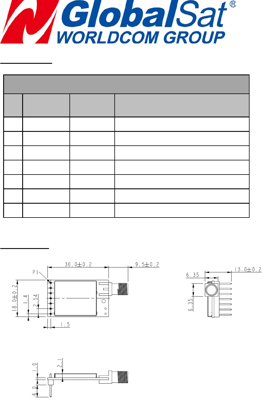
LR-101H Pin Definition
Pin Signal
name I/O Description
1 GND - Ground
2 VCC - 3.0V~6.0V
3 RXD Input UART input
4 TXD Output UART output
5 BZ Output Module’s operation status
6 P2 Input Pin2 for switching operation mode
7 P1 Input Pin1 for switching operation mode
Product Size

Operation Mode
There are four operating modes of LR-101H.
1. Normal mode 2.Wake-up mode 3.Power-saving mode 4.Setup mode.
The four operation modes are switched by the signal level of P1 and P2.
Mode 1: Normal mode (P1=0, P2=0)
UART is opened. Wireless channel is opened. Penetrating transmission.
Mode 2: Wake-up mode (P1=0, P2=1)
UART is opened. Wireless channel is opened. The only difference from normal mode
is that its preamble is longer than normal mode’s, so that it can make sure the
receiver could be waked in the power-saving mode.
Note: The receiver could be waked no matter it is in normal mode or wake-up mode
or power-saving mode. The receiver would automatically add the RSSI at the end of
the received data.
Mode 3: Power-saving mode (P1=1, P2=0)
UART is closed. The wireless channel is in power-saving mode. You can set up an
interval from 0.5 to 5 seconds to wake up in power-saving mode to check if there is
preamble. If the receiver receives preamble, it will open UART, and wake MCU to
process the received data and return data. After that, it will return to the power-saving
mode.
Mode 4: Setup mode (P1=1, P2=1)
UART is closed. Wireless channel is closed. It could only be configured.

Application Note
1. For proper operation of LR-101H, do not leave P1 or P2 floating. Do keep P1
and P2 at fixed level; otherwise it might cause the module instable.
2. Antenna is the important part in the communication system. The quality of
antenna would directly influence the communication. Please take the antenna
type and antenna’s electrical characteristics into consideration while
integrating LR-101 into product.
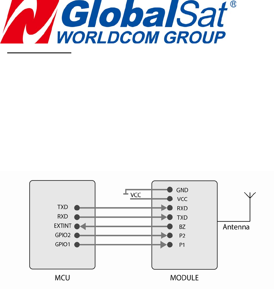
The Connection Diagram of the Module with MCU:

Parameter Setting
The configuration of LR-101H is programmed by hexadecimal notation. The
default of baud rate is 9600bps. You can read and write the setting as below:
1) Read the setting: 0xFF 0x4C 0xCF 0x52 0xA1 0x52 0xF0 (7 bytes)
Response:
Preamble Model
Name
FW
Version
LoRa MAC
Address
Group
ID
RF
Frequency
RF TRx
Rate
RF
Power
UART
Baud Rate
UART
Parity
Wakeup
Time
End
Word
0x24
(1 byte) 4 bytes 7 bytes 8 bytes 1 byte 3 bytes 1 byte 1 byte 1 byte 1 byte 1 byte
0x21
(1 byte)
2) Write the setting:
Header of writing command RF
Frequency
Group
ID
RF TRx
Rate
RF
Power
UART
Baud Rate
UART
Parity
Wakeup
Time
0xFF 0x4C 0xCF 0x52 0xA1 0x57 0xF1
(7 byte) 3 bytes 1 byte 1 byte 1 byte 1 byte 1 byte 1 byte
Response:
Preamble Model
Name
FW
Version
LoRa
MAC
Address
Group
ID
RF
Frequency
RF TRx
Rate
RF
Power
UART
Baud
Rate
UART
Parity
Wakeup
Time
End
Word
0x24
(1 byte) 4 bytes 7 bytes 8 bytes 1 byte 3 bytes 1 byte 1 byte 1 byte 1 byte 1 byte 0x21
(1 byte)

The parameters are presented as hexadecimal.
Parameter Name Bytes Description
Model Name 4
Show the last 4 characters of model number in hexadecimal
format. The last 4 characters of LR-101H are 101H. The
hexadecimal of 101H is 0x31 0x30 0x31 0x4C. Model Name is
written in FLASH memory and could not be modified.
FW Version 7
Show the last 7 characters of firmware version in hexadecimal
format.
EX: The hexadecimal of 1507291. is 0X31 0x35 0x30 0x37 0x32
0x39 0x31. FW Version is written in FLASH memory and could
not be modified.
LoRa MAC Address 8
Show the last 8 characters of MCU ID. If MCU is changed, the
LoRa Mac address must also be changed. LoRa Mac Address is
written in FLASH memory and could not be modified.
EX. 0x2A 0x1D 0x1C 0X1D 0x1E 0x1F 0x2A 0x2B
Group ID 1
The range is from 0 to 255. Please set the same group ID for the
same group’s devices for proper communication in the same
group.
(Default: 0, this function is disabled.)
RF Frequency 3 The unit is KHz.
(Default: 915000KHz, which is presented as 0x0D 0xF6 0x38.)
RF TRx Rate 1
0.81K, 1.46K, 2.6K, 4.56K, 9.11K, 18.23Kbps are represented as
0x00 to 0x05.
(Default: 4.56Kbps, which is presented as 0x03)
RF Power 1
The range is from 0 to 7. It is represented as 0x00 to 0x07. It
would increase about 2dBm while increasing 1 to this parameter.
(Default: 20dBm, which is presented as 0x07)
UART Baud Rate 1
1200,2400,4800,9600,19200,38400,57600 bps are represented
as 0x00 to 0x06.
(Default: 9600 bps, which is presented as 0x03)
UART Parity
1
No parity check is presented as 0x00. Odd parity check is
presented as 0x01. Even parity check is presented as 0x02.
(Default: no parity check, which is presented as 0x00)
Wakeup Time 1
50ms,100ms,200ms,400ms,600ms,1s,1.5s,2s,2.5s,3s,4s,5s are
presented as 0x00 to 0x0b.
(Default: 1sec, which is presented as 0x05)

For example, Module setting is as below:
Group ID is 0. Air rate is 0.81K bps. RF frequency is 915.000MHz. RF power is 20dBm.
UART Baud Rate is 9600bps. UART parity is none. Wakeup time is 1 sec.
Write the setting:
0xFF 0x4C 0xCF 0x52 0xA1 0x57 0xF1 0x0D 0xF6 0x38 0x00 0x00 0x07 0x03 0x00 0x05
Response:
0x24 0x31 0x30 0x31 0x4C 0x31 0x35 0x30 0x37 0x32 0x39 0x31 0x2A 0x1D 0x1C 0X1D
0x1E 0x1F 0x2A 0x2B 0x00 0x0D 0xF6 0x38 0x00 0x07 0x03 0x00 0x05 0x21

Design Note
The LR-101H LoRa modules are for being integrated into your devices for applying
the LoRa technology, you can refer to the page3 of this doc.
1. GND under module should be kept into integrity.
2. Power Filter circuitry and matched resistance should be close to module.
3. The placement of the module should be kept away from the interfering
source, such as WiFi Antenna, GSM Antenna, DDR CLK, and LCD line
bundle, etc.
Quality Guarantee
LR-101H has been certificated with FCC, FCC ID certification number:
RID-LR101H. To ensure the quality, every single device has to pass through
testing and must be scrupulously checked for imperfections.
Trademark:
Product Name: LoRa Wireless Module
Model No.: LR-101H
FCC ID: RID-LR101H
ManualandProductLabelingInformationTotheEndUser
Theendusermanualshallincludeallrequiredregulateorinformation/warningasshowninthis
manual.Andwhenthismoduleisinstalledinthehostproduct,youmustincludea“ContainsFCC
ID:RID‐LR101H”inthelabelofthehostproduct.

6
FCC warning:
For Customers in the United States:
Any Changes or modifications not expressly approved by the party responsible for compliance could
void the user’s authority to operate the equipment.
This device complies with part 15 of the FCC Rules. Operation is subject to the following two
conditions: (1) This device may not cause harmful interference, and (2) this device must accept any
interference received, including interference that may cause undesired operation.
This equipment complies with FCC radiation exposure limits set forth for an uncontrolled
environment. This equipment should be installed and operated with minimum distance 20cm
between the radiator& your body.
This transmitter must not be co-located or operating in conjunction with any other antenna or
transmitter.
Note: This equipment has been tested and found to comply with the limits for a Class B digital device,
pursuant to part 15 of the FCC Rules. These limits are designed to provide reasonable protection
against harmful interference in a residential installation. This equipment generates uses and can
radiate radio frequency energy and, if not installed and used in accordance with the instructions, may
cause harmful interference to radio communications. However, there is no guarantee that interference
will not occur in a particular installation. If this equipment does cause harmful interference to radio or
television reception, which can be determined by turning the equipment off and on, the user is
encouraged to try to correct the interference by one or more of the following measures:
—Reorient or relocate the receiving antenna.
—Increase the separation between the equipment and receiver.
—Connect the equipment into an outlet on a circuit different from that to which the receiver is
connected.
—Consult the dealer or an experienced radio/TV technician for help.