GlobalSat WorldCom TR151A GPS TRACKER User Manual USERS MANUAL
GlobalSat WorldCom Corporation GPS TRACKER USERS MANUAL
UserManual.wiki
>
GlobalSat WorldCom
>
TR151A User Manual
USERS MANUAL
Navigation menu
Upload a User Manual
Namespaces
Wiki Guide
HTML
PDF
Info
Views
User Manual
Discussion / Help
Navigation
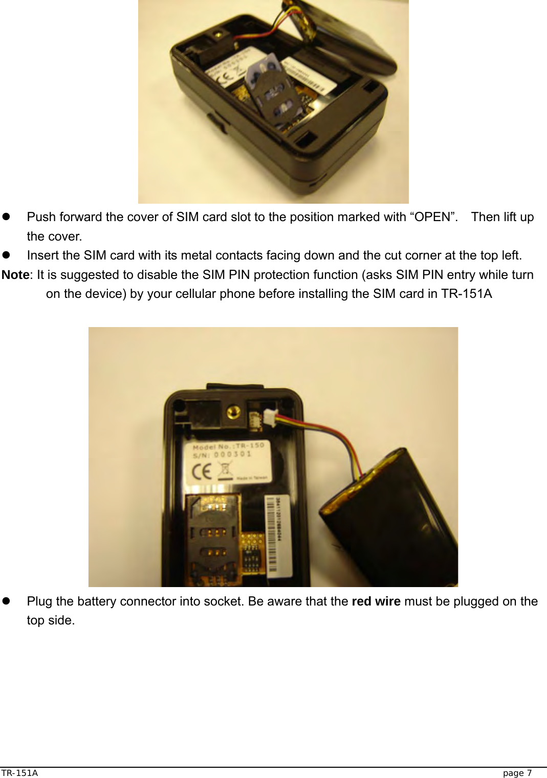
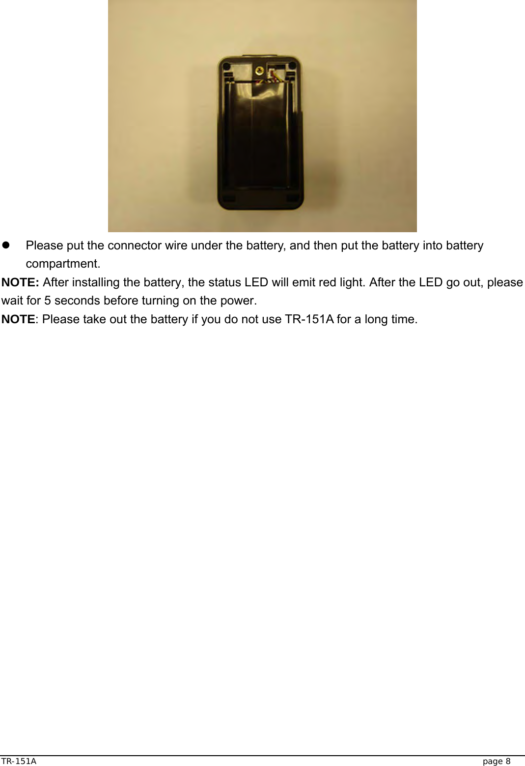
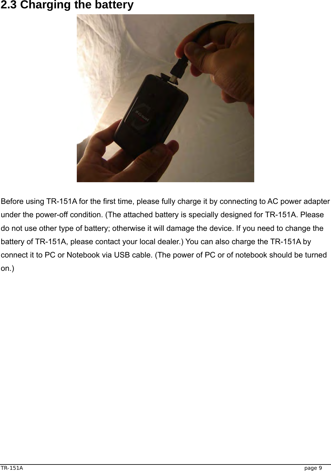
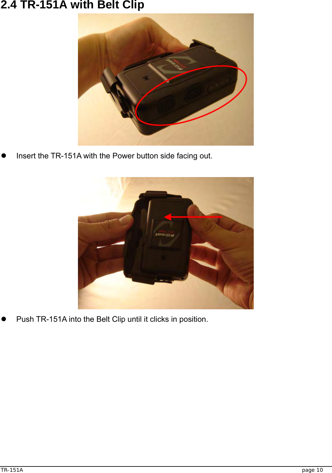
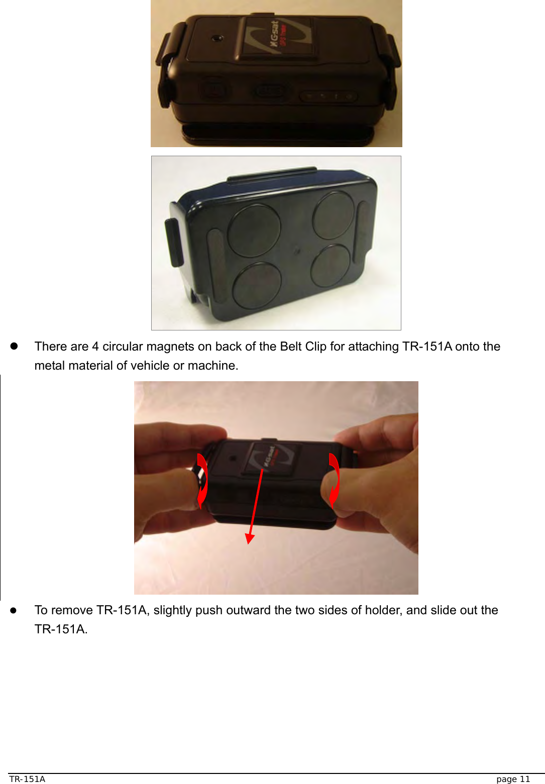
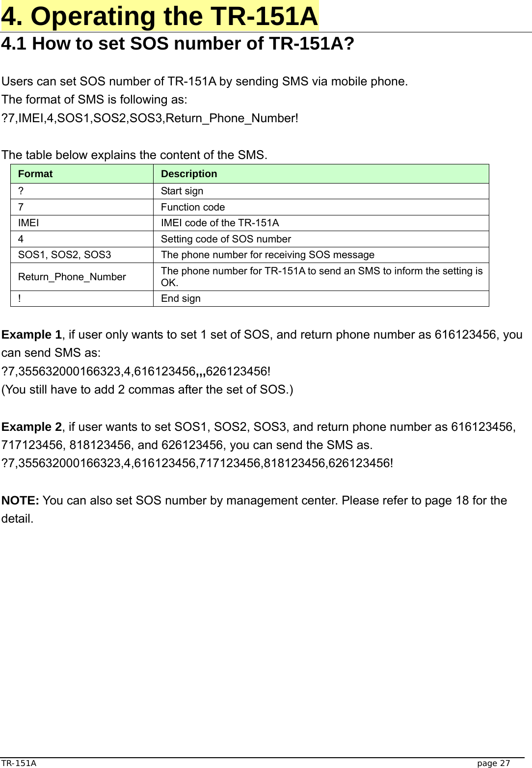
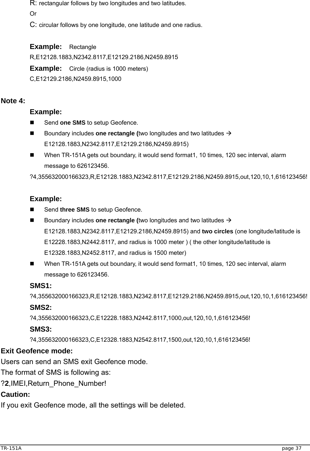
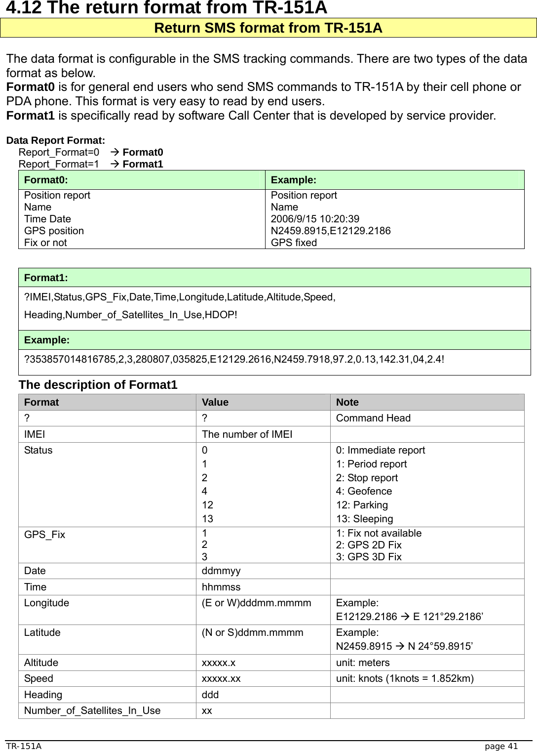
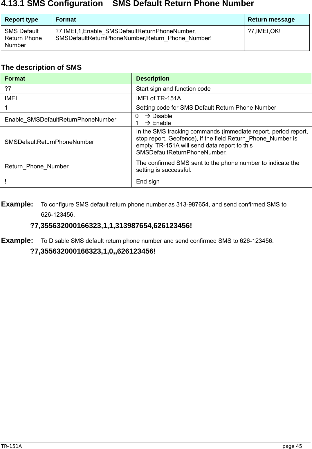
![TR-151A page 35 4.8 How to set TR-151A enter Geofence mode? Users can send SMS to TR-151A for setting up to 10 permissible or restricted areas whose shape is circular or rectangular for tracking the vehicles or monitoring the equipment/assets. Users can choose to receive alarm message while TR-151A enters the restricted areas or to receive alarm message while TR-151A gets out the permissible areas. The content of the SMS includes the rectangular or circular areas defined by longitudes and latitudes, getting in the restricted areas or getting out the permissible areas to send alarm, time intervals of alarm report, number of reports, report format and return phone number. The format of SMS is as below. Report type Format Return message 4 SMS Geofence ?4,IMEI,{[R,longitude,latitude,longitude,latitude], [C,longitude,latitude,radius(meter)]},In_or_Out, Report_Interval,Number_of_Reports,Report_Format, Return_Phone_Number! ?4,IMEI,OK! 11 GPRS Geofence ?11,IMEI,{[R,longitude,latitude,longitude,latitude], [C,longitude,latitude,radius(meter)]},In_or_Out, Report_Interval,Number_of_Reports,Report_Format, Return_Phone_Number! ?11,IMEI,OK! The description of SMS Format Description ?4 ?11 Start sign and function code ?4 Æ Send location info to mobile phone. ?11 Æ Send location info to TR-151A call center IMEI IMEI of TR-151A {[R,longitude,latitude,longitude,latitude],[C,longitude,latitude, radius(meter)]} Boundary information: R: rectangular shape Æ Follow by two longitudes, latitudes. C: circular shape Æ Follow by one longitude, latitude and one radius. In_or_Out In_or_Out=in Æ Send alarm message if TR-151A gets in the restricted areas. In_or_Out=out Æ Send alarm message if TR-151A gets out the permissible areas. Report_Interval Time interval of sending data report. The unit is second. Number_of_Reports Set how many reports will be sent? Number_of_Reports=0 Æ continuous report Number_of_Reports=X Æ X times report Report_Format Set TR-151A to return message by Format0 or Format1. (see description below) Return_Phone_Number ?4: The phone number for receiving return message and alarm message. ?11:The phone number for receiving return message ! End sign](https://usermanual.wiki/GlobalSat-WorldCom/TR151A/User-Guide-943416-Page-35.png)
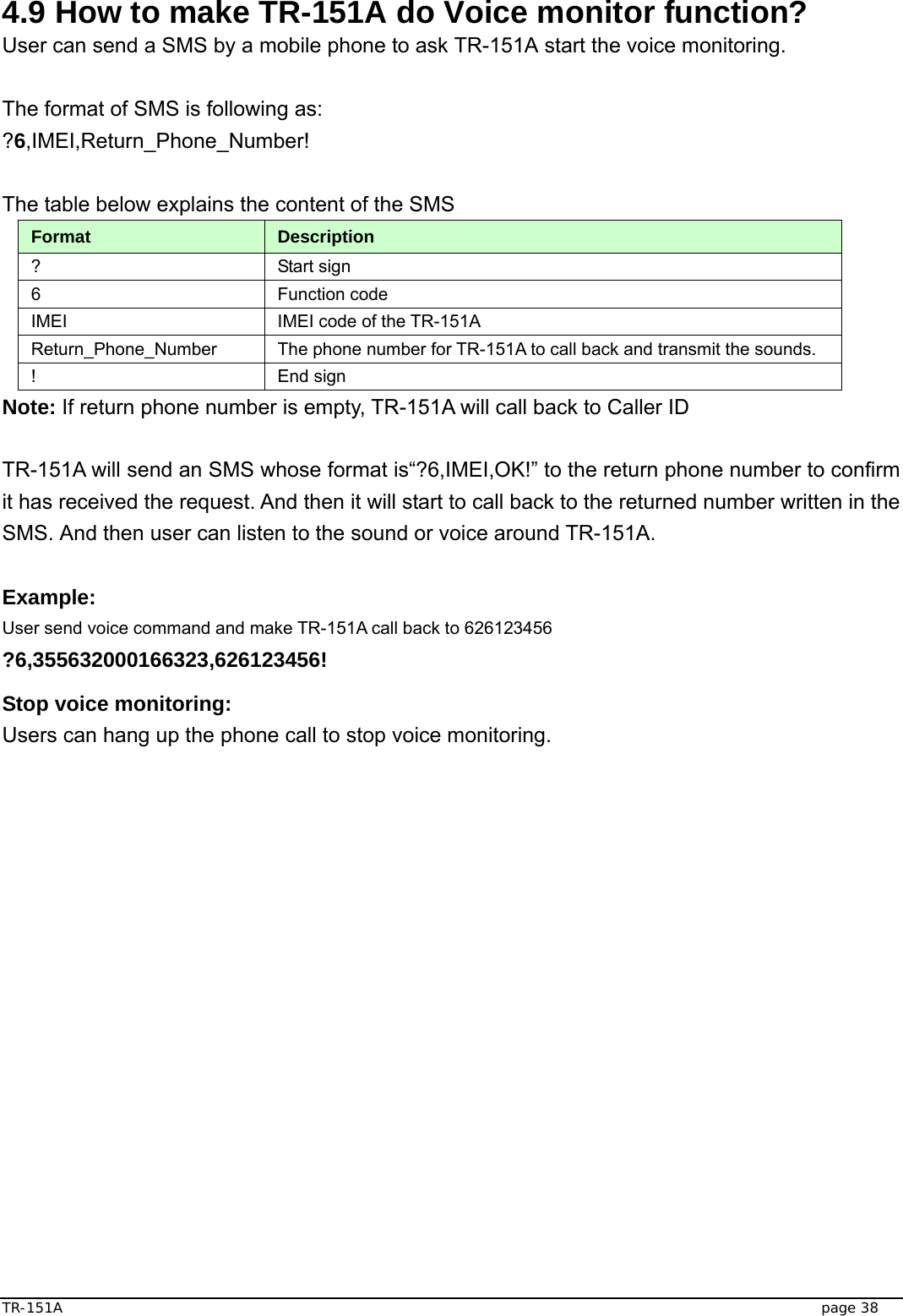
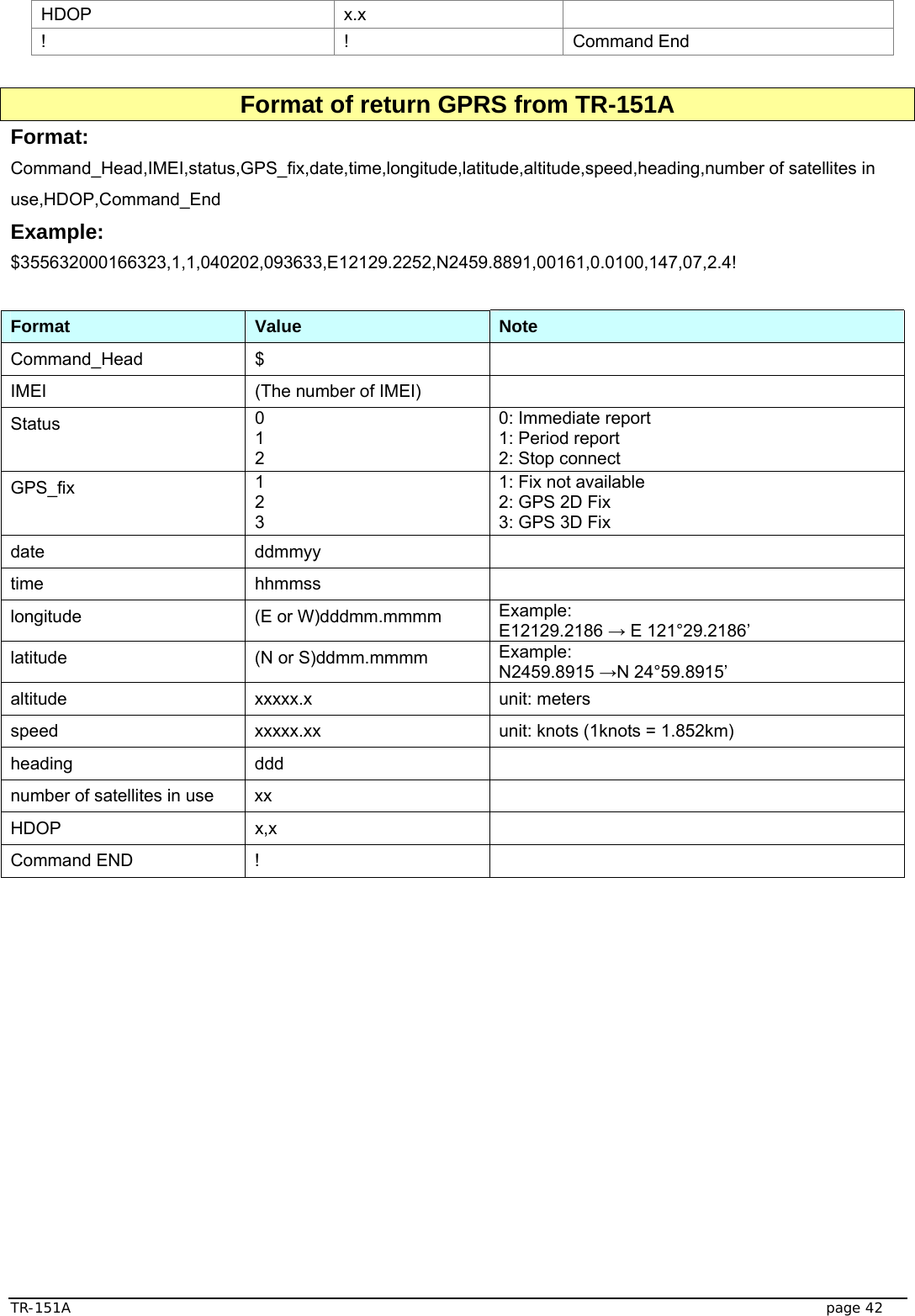
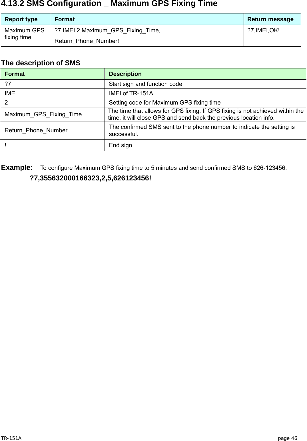
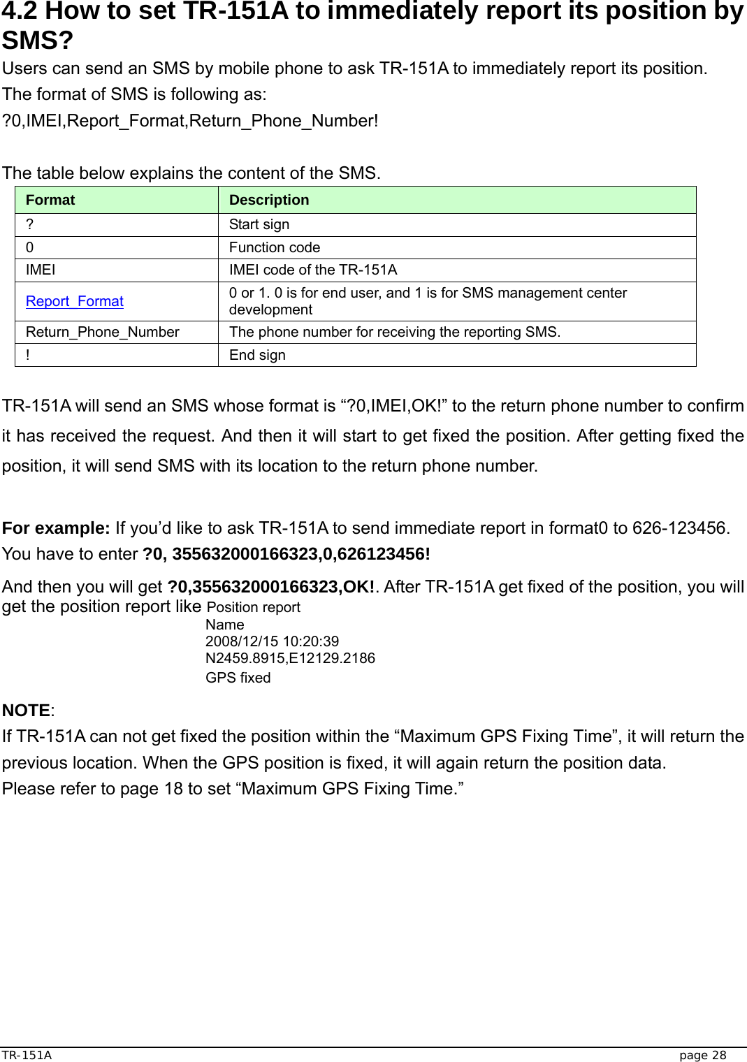
![TR-151A page 36 Note 1: The format of Google map/earth’s longitudes and latitudes differs from the format of TR-151A’s. So please convert the format of Google map/earth’s longitudes and latitudes into the format of TR-151A’s longitudes and latitudes before setting Geofence. If you get a set of latitude and longitude from Google earth like 24°59’47.40” & 121°29’15.72”, you have to convert the format to TR-151A format as below and then set geo-fence. 47.40 ÷60=0.79 15.72÷60=0.262 Please take E 12129. & 262 N2459.79 to set geo-fence If you get a set of latitude and longitude from Google earth like 24.9965°& 121.4877°, you have to convert the format to TR-150 format as below and then set geo-fence. 0.9965 x60=59.79 0.4877 x60=29.262 Please take E12129. 262 & N2459.79 to set geo-fence Note 2: User can set up to 10 rectangular or circular boundaries. Each SMS contains one boundary setting. User can send numerous SMS to complete one set of settings, including numerous rectangular or circular boundaries. For example, if user wants to set the boundary includes 2 rectangles and 1 circle. User has to send 3 SMS, two with rectangle information, one with circle information. SMS1: ?4,IMEI,R,longitude,latitude,longitude,latitude,In_or_Out,Report_Interval, Number_of_Reports,Report_Format,Return_Phone_Number! SMS2: ?4,IMEI,R,longitude,latitude,longitude,latitude,In_or_Out,Report_Interval, Number_of_Reports,Report_Format,Return_Phone_Number! SMS3: ?4,IMEI,C,longitude,latitude,radius,In_or_Out,Report_Interval, Number_of_Reports,Report_Format,Return_Phone_Number! If user uses numerous SMS in one setting, the IMEI, In_or_Out, Report_Interval, Number_of_Reports, Report_Format, Return_Phone_Number must be the same between each SMS. If above parameters are not the same between SMS, TR-151A only follows last SMS. Note 3 In Boundary information {[R,longitude,latitude,longitude,latitude],[C,longitude,latitude,radius],} User can set](https://usermanual.wiki/GlobalSat-WorldCom/TR151A/User-Guide-943416-Page-36.png)