Globalscale Technologies 003-DS2XXXW DREAMPLUG WIFI User Manual DreamPlug User Guide CE FCC 20110316
Globalscale Technologies INC DREAMPLUG WIFI DreamPlug User Guide CE FCC 20110316
Users Manual

Quick Start Guide – DreamPlug page 1/11
DreamPlug User Guide
Thank you for purchasing our DreamPlug – The Power to Innovate!
This is running at 2.4GHz yet using less than 10W power consumption. This little palm-sized powerhouse can handle all your
biggest tasks while still saving about 96% on energy costs when compared to the average 175 Watt desktop computer. You can
customize your Plug to work in almost any industry - Cloud ComputingˈHome / Industrial Automation, Security/Surveillance,
Medical Monitoring and Data Capture , High End Audio SystemsˈNetwork Storage and monitoring , VoIP and IPPBXˈSmart Grid
/Mesh . You can never have enough storage, not to mention fast access to all that data. That's why we have provided Wi-Fi,
Bluetooth, Gigabit Ethernet, USB 2.0 and eSATA connection options to the Server line of products. as the AUDIO INTERFACE,
the dreamplug can play the music or others data from this port to the external speaker or others devices.in a word, Go ahead
give us what you got, we can take it.
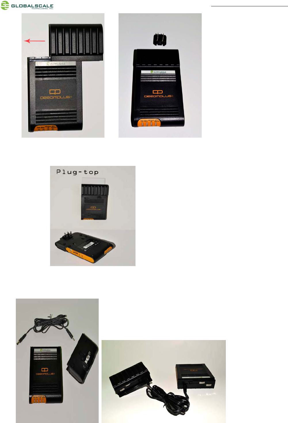
Package contents
DreamPlug Content List Remark
1 DreamPlug 1 unit
2 Detachable AC-DC Power Supply Unit 1 pc
3 Detachable DC-DC Power Cable 1 pc
4 Detachable AC Slider 1 pc
5 Detachable AC Power Cord Adaptor 1 pc
6 AC power Cord 1 pc
7 Protective Slide Cover for DreamPlug 1 pc
8 Protective Slide Cover for Power Supply Unit 1 pc
9 Ethernet Cable 1 pc
10 Warranty Card 1 pc
11 Quick Reference Guide 1 pc
12 External JTAG Debug Module No Optional item. Not included
Note 1: All files will be available download: https://www.globalscaletechnologies.com/t-downloads.aspx
Note 2: JTAG debug module is sold separately. It’s highly recommended for you to purchase this module to use in programming and debugging.
Note3: This device has been integrated with internal antenna, no external antenna is needed. for more details of the antenna ,please refer to the EUT
Photo in the test report.
A. FOR INITIAL USE
1. To be used as a Plug Computer:
GTI-2010.12.10
Quick Start Guide – DreamPlug page 2/11
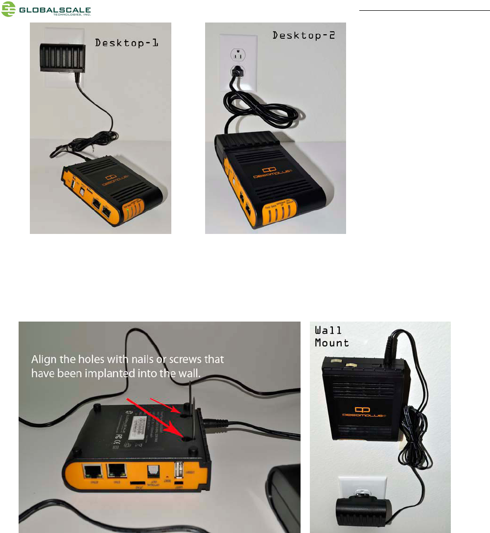
2. To Be Used as a “Desk Top” Computer.
Quick Start Guide – DreamPlug page 3/11
3. To Have the “DreamPlug” Wall Mounted.
Quick Start Guide – DreamPlug page 4/11
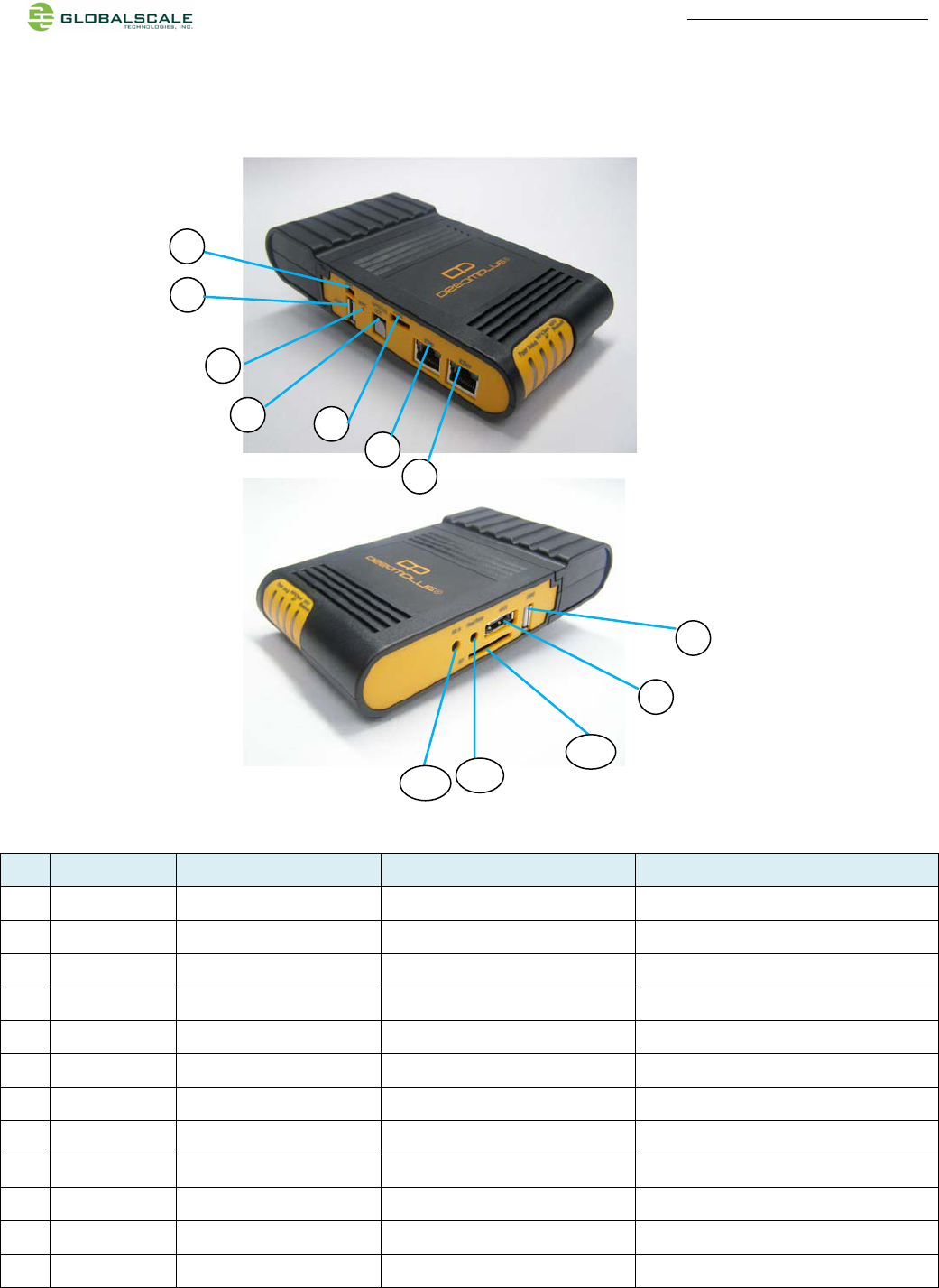
B. DreamPlug Server appearance and connecting ports
Ports description- DreamPlug Server
Connection port Description Remark Use
1 RJ45 #1 Gigabit Ethernet port 1 CAT5e or CAT6 cable Connect to internet to read the data from the USB
Connect to internet to read the data from the USB
2 RJ45 #2 Gigabit Ethernet port 2 CAT5e or CAT6 cable
3 JTAG port Debug interface For JTAG board connection only
4 Optical out S/PDIF digital audio out Digital audio optical out
5 Reset button System reset
6 USB port #1 USB 2.0 high speed host USB device storage
7 UART port Debug interface For JTAG board connection only
8 USB port #2 USB 2.0 high speed host USB device storage
9 eSATA eSATA port Hard drive storage
10 SD Secure Disk card slot for user expansion/ application
11 Head Phone Analog audio out Analog audio headphone out
12 Mic in Analog microphone in Sound recording
Remark: the USB port just for the storage read,the user can read the data through the USB port which connect
the storage devices,for example,U disk.it cann't use when direct connect to the computer.
The Audio Interface:when plug the audio devices,can export out the audio signal from this port.
For example,the device play the music,which read the data from the momery.the audio interface
connet to the speaker,and will be a audio signal from this port.
9
8
1 Remark:the RJ45 can not work when direct connect to the computer
it need to connect through the router then work.
2
3
6
4
7
5
11
12
10
the USB port statement
the audio interface function statement
RJ45 Function
Quick Start Guide – DreamPlug page 5/11
Ports description- DreamPlug Server
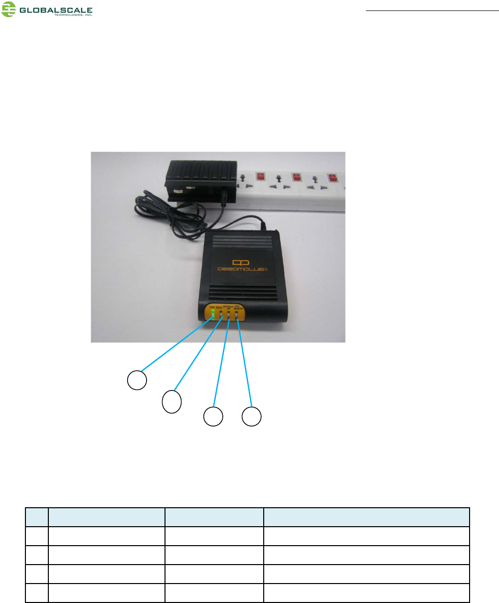
C. LED indication
D. LED indication table
LED Color/ Pattern Description
1 Power on LED Solid green Upon power on, this LED lights up
2 WiFi AP mode Solid blue WiFi will go into AP mode as default after boot up
3 WiFi Client mode Solid green Light up when change to client mode by user
4 Bluetooth Blinking blue Bluetooth will be on as default after boot up
2
3 4
1
Quick Start Guide – DreamPlug page 6/11
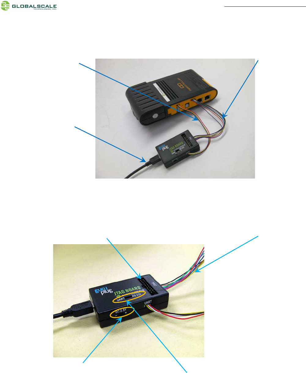
E. Connect to JTAG board
F. Tools and files you need to start debugging
1. Prepare one PC with Fedora 9 (or Fedora 11) Linux operating system
2. Download and install the following tools and utilities
2. Connect 8 pin JTAG cable
1. Connect 4 pin UART cable
3. Connect Mini USB cable here.
The other end to computer’s
USB port.
This is the standard 20pin JTAG connector which has the same pin signals as 8 pin cable
Normally, this switch (or jumper wire) should
be on the left side for UART selection
This DC 2.5V is for Dream Plug CPU
e-fuse programming only, do not use it
for other purpose.
Quick Start Guide – DreamPlug page 7/11
File name Description Where to get it
1 Minicom Used as Board console Re-Install command: yum install minicom
note 1: Fedora9 has a built-in minicom
2. Ftdi_sio.ko FTDI device driver
module for Linux
http://www.globalscaletechnologies.com/t-downloads.aspx
3. Ftdi_sio.ko FTDI device driver
module for Linux
http://www.globalscaletechnologies.com/t-downloads.aspx
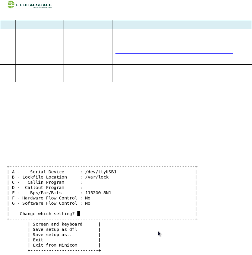
3. Setup minicom
# minicom –s
Set the Configure properties as follows:
Bits per sec field to 115200
Data bits to 8
Parity to None
Stop bit to 1
Flow Control to None
G. Basic procedures for debugging
1. Connect cables as illustrated in section D.
2. Run terminal program on Linux PC.
3. Type in # minicom –o marvell
4. Power on the DreamPlug Server.
Normally , you will see messages on screen as below˖
U-Boot 2010.06-02334-g8f495d9-dirty (Dec 21 2010 - 15:27:37)
Marvell-GuruPlug
SoC: Kirkwood 88F6281_A0
DRAM: 256M
Quick Start Guide – DreamPlug page 8/11
SF: Detected MX25L3205D with page size 256, total 4 MiB
*** Warning - bad CRC, using default environment
In: serial
Out: serial
Err: serial
Net: egiga0, egiga1
88E1121 Initialized on egiga0
88E1121 Initialized on egiga1
Hit any key to stop autoboot: 0
You can press any key to stop auto-boot when you see the boot delay timer is counting down.
After entering the uboot prompt, you can also change the uboot environment variables such as boot delay time,
Ipaddr, serverip and so on.
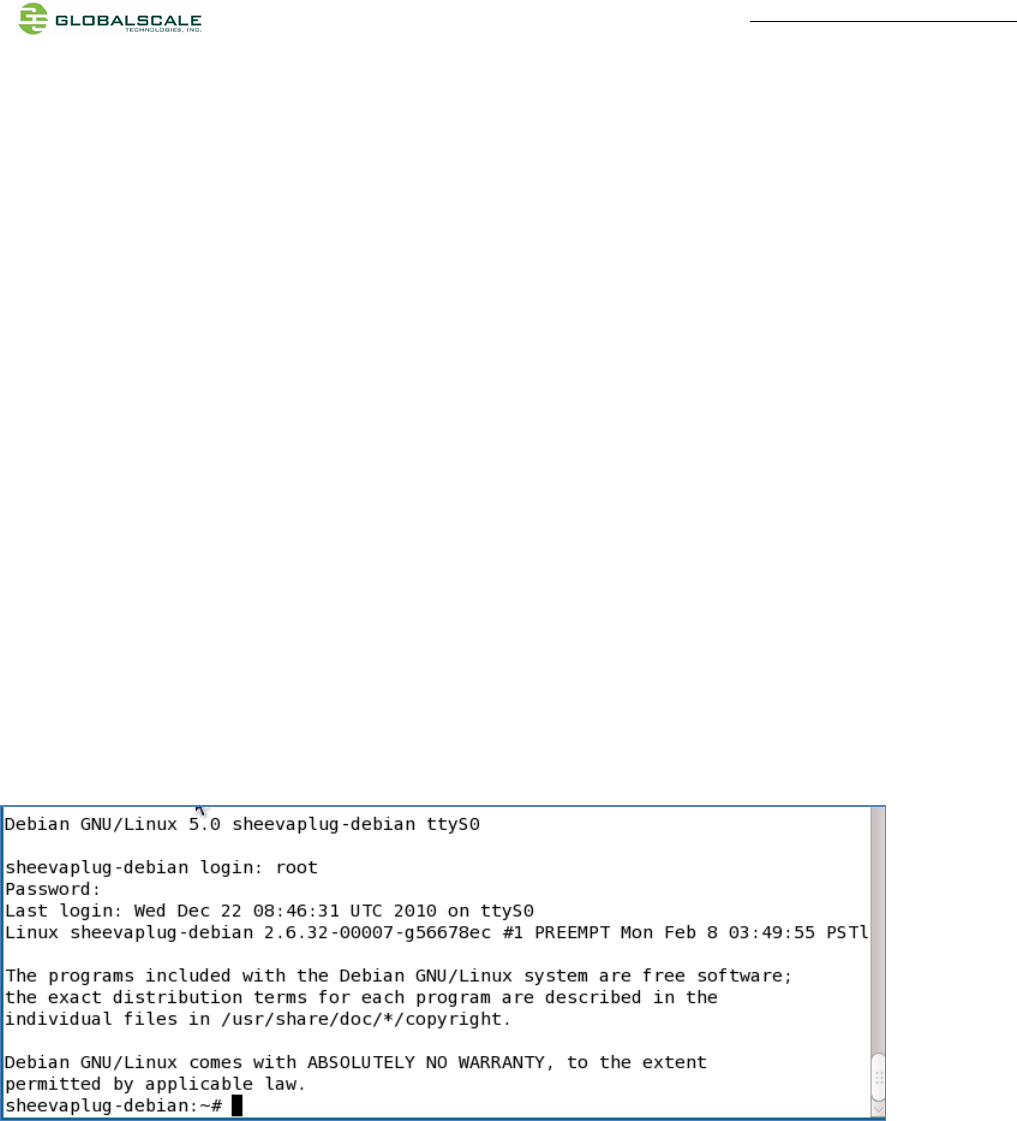
If no key has been pressed to interrupt the uboot, it will continue running to the login screen where it urges you to
input the login name and password, here is the default login information.
Login : root
Password: nosoup4u
Now, you have the full control right of it.
H. Wi-Fi / Bluetooth
DreamPlug Server has a built-in WiFi module which is compliance with 8.2.11 b/g standard and Bluetooth 2.1 +
Enhanced data rate (EDR).
The WiFi works as both client and AP mode but only one at a time.
Quick Start Guide – DreamPlug page 9/11
The default mode is AP mode every time when it powers on and can be switched to client mode manually by
entering the setup page, please follow the procedures below to set-up the functionalities for WIFi and Bluetooth.
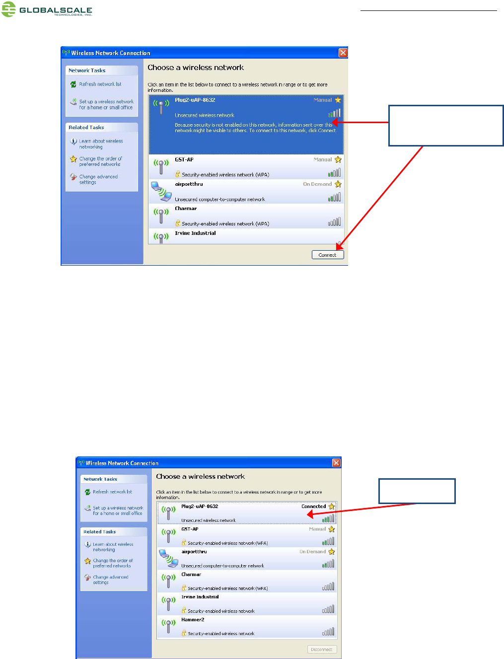
1. Prepare a Bluetooth earphone and one computer installed with Wi-Fi Lan card, here we use computer with
Windows XP operating system for example.
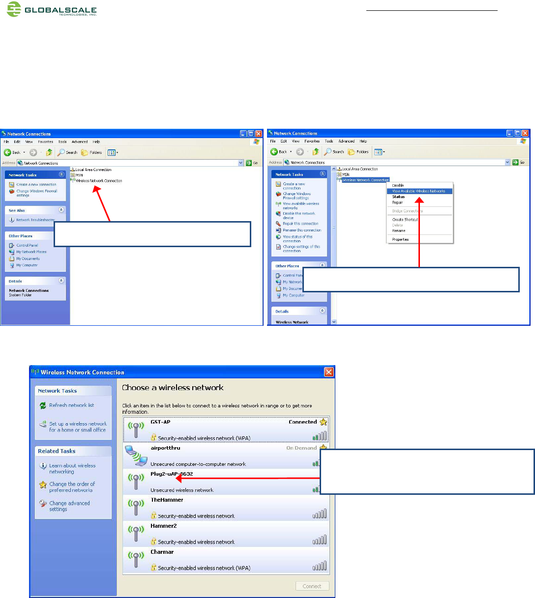
2. Go to “Network Connections”
3. Select “Wireless Network Connection”
4. Select “View Available Wireless Networks”
5. Choose name start with “plug2-uAP-xxxx”
xxxx are last digits of the MAC address
Quick Start Guide – DreamPlug page 10 /11
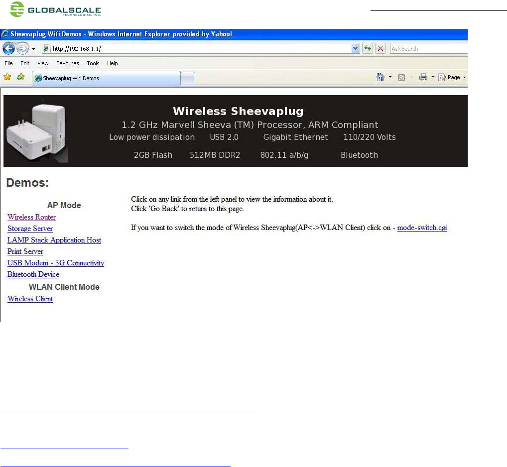
8. Open internet browser, enter address: 192.168.1.1, you will see the web page as below.
This is the setup page for this DreamPlug Server, please follow the instruction and link on the page for configuration.
6. Choose one and
click here to connect.
7. Connected
Quick Start Guide – DreamPlug page 11 /11
I. Download sites
To download the files for Dreamuplug server, please visit:
http://www.globalscaletechnologies.com/t-downloads.aspx
Other useful resource links are:
http://www.plugcomputer.org/
http://plugcomputer.org/plugwiki/index.php/GuruPlug
and the same as the wifi,when using the wifi, the bluetooth will not work.
the bluetooth and wifi module uses the same module,and the same antenna,when using the bluetooth,the wifi will not work
================================================================
FCC NOTE:
This device complies with Part 15 of the FCC Rules. Operation is subject to
the following two conditions:(1)this device may not cause harmful
interference, and (2) this device must accept any interference received,
including interference that may cause undesired operation.
The manufacturer is not responsible for any radio or TV interference caused
by unauthorized modifications to this equipment.Such modifications could void
the user's authority to operate the equipment.
To maintain compliance with FCC's RF exposure guidelines, this equipment should
be installed and operated with minimum separation distance of 20cm between the
radiator and your body. Use only the supplied antenna.
================================================================