Globalscale Technologies 003GP1 GuruPlug User Manual
Globalscale Technologies INC GuruPlug
UserManual.wiki
>
Globalscale Technologies
>
003GP1 User Manual
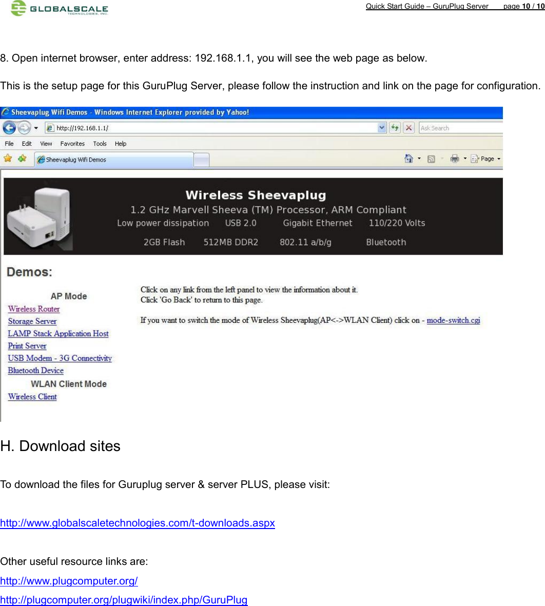
User Manual
Navigation menu
Upload a User Manual
Namespaces
Wiki Guide
HTML
PDF
Info
Views
User Manual
Discussion / Help
Navigation