Globalstar USA FAU200RA Globalstar Fixed Access Unit with Remote Antenna User Manual Front
Globalstar USA, LLC Globalstar Fixed Access Unit with Remote Antenna Front
User Manual

Description of the Globalstar System GS-TR-94-0001
Revision E
Page i
Description
of the
Globalstar System
December 07, 2000

Description of the Globalstar System GS-TR-94-0001
Revision E
Page ii
DOCUMENT REVISION HISTORY
1
Revision Date of Issue Scope
A6/3/94 Incorporated QUALCOMM Comments
B12/20/94 Updated after SRR/PDR Reviews
C8/10/95 Updated after the HLDR Reviews
D2/24/97 Update to incorporate design changes
E12/07/00 Added Photographs & Revised Services
2
3
Abstract4
5
6
This document is written to introduce new people to Globalstar. It7
attempts to provide a general overview of the system and to provide some8
information on the design of the system. It also attempts to define how9
Globalstar is envisioned to operate. As such, this is primarily tutorial in10
nature. In the interests of brevity, simplifications are made in the material11
herein. There is no attempt to be totally complete or comprehensive for all12
cases.13
14
This document should not be interpreted as a binding specification. It does15
not contain requirements that should be interpreted as either complete or16
binding. Globalstar is an evolving system. This document will be updated17
as the design of the system progresses. When each revision is issued there18
is an attempt to represent the current thinking on the system.19
20
For binding specifications and requirements please consult the released21
requirements documents and the released design information.22
23
24
Globalstar, L.P.
3200 Zanker Road
San Jose, Ca. 95164-0670
Copyright © 1997 Globalstar, L.P. All rights reserved. Printed in the United States of America.

Description of the Globalstar System GS-TR-94-0001
Revision E
iii
Contents1
1. SERVICES OFFERED 1-12
1.1 Service Types..........................................................................................................1-13
1.2 IS-41 Services .........................................................................................................1-14
1.3 GSM Services..........................................................................................................1-85
1.4 Globalstar Specific Services and Quality ........................................................1-156
1.5 External Network Supported Services ............................................................1-177
2. SYSTEM SEGMENT DESCRIPTIONS 2-18
2.1 Globalstar System..................................................................................................2-19
2.2 User Terminal.........................................................................................................2-310
2.2.1 Hand Held and Mobile Units.........................................................................2-311
2.2.2 Fixed Terminals...............................................................................................2-712
2.3 Gateway....................................................................................................................2-813
2.4 User Terminal and Gateway Interaction........................................................2-1214
2.5 Globalstar Control Centers................................................................................2-1315
2.5.1 Ground Operations Control Center............................................................2-1416
2.5.2 Satellite Operations Control Center..........................................................2-1717
2.5.3 Globalstar Business Office ...........................................................................2-1918
2.6 Globalstar Satellite..............................................................................................2-2019
3. FREQUENCIES AND COVERAGE ANALYSIS 3-120
3.1 Frequency Plans....................................................................................................3-121
3.2 Satellite Antenna Beam Configuration............................................................3-222
3.3 Earth Surface Coverage.......................................................................................3-723
3.4 Position Determination.......................................................................................3-1024
3.5 Channel Characteristics.....................................................................................3-1225
3.6 Link Analysis........................................................................................................3-1426
4. CODE DIVISION MULTIPLE ACCESS (CDMA) 4-127
4.1 Introduction ............................................................................................................4-128
4.2 Diversity Combining.............................................................................................4-229
4.3 Fade Mitigation......................................................................................................4-230
Description of the Globalstar System GS-TR-94-0001
Revision E
iv
4.4 Acquisition...............................................................................................................4-31
4.5 Forward CDMA Channel .....................................................................................4-52
4.6 Return Link CDMA Channel............................................................................4-103
4.7 CDMA End to End Performance ......................................................................4-124
5. TERRESTRIAL INTERFACE 5-15
5.1 Telecommunication Network Interface.............................................................5-16
5.2 Registration Process..............................................................................................5-47
5.3 Authentication Process.........................................................................................5-78
5.4 GSM - A Interface in Globalstar .......................................................................5-109
6. CALL PROCESSING 6-110
6.1 Call Processing between Globalstar and PLMN .............................................6-111
6.2 TIA and ETSI Call Flow Examples ...................................................................6-512
13

Description of the Globalstar System GS-TR-94-0001
Revision E
v
Figures1
Figure 2-1 Globalstar System Integrates with Terrestrial Network........................ 2-12
Figure 2-2 Globalstar Constellation Serves Temperate Areas.................................. 2-23
Figure 2-3 Typical Hand Held User Terminal ............................................................. 2-34
Figure 2-4 Globalstar User Terminal Block Diagram................................................. 2-55
Figure 2-5 User Terminal Startup Scenario within Globalstar ................................. 2-66
Figure 2-6 Typical Fixed Terminal Application........................................................... 2-77
Figure 2-7 Typical Gateway Installation....................................................................... 2-88
Figure 2-8 Gateway Simplified Block Diagram............................................................ 2-99
Figure 2-9 Globalstar Control Center ......................................................................... 2-1310
Figure 2-10 Ground Segment Support for Communications.................................... 2-1411
Figure 2-11 GOCC Simplified Block Diagram............................................................ 2-1512
Figure 2-12 Ground Equipment Support for T&C Functions................................... 2-1713
Figure 2-13 Spacecraft Bus Characteristics - Highly Autonomous......................... 2-2014
Figure 2-14 Communications Payload Pictorial......................................................... 2-2115
Figure 2-15 Communications Payload Simplified Block........................................... 2-2116
Figure 2-16 Satellite T&C - Compatible with Communications .............................. 2-2217
Figure 3-1 Frequency Plan - Emphasizes Conservation of Spectrum....................... 3-118
Figure 3-2 S - Band Beams.............................................................................................. 3-219
Figure 3-3 L- Band Beams............................................................................................... 3-320
Figure 3-4 L - Band Channel Frequencies .................................................................... 3-421
Figure 3-5 S - Band Channel Frequencies..................................................................... 3-422
Figure 3-6 Full Earth Coverage-Except Polar Regions............................................... 3-723
Figure 3-7 Enhanced Coverage for Temperate Regions ............................................. 3-824
Figure 3-8 Orbital Parameters for Globalstar Satellites............................................ 3-925
Figure 3-9 Channel Characteristics Considerations................................................. 3-1226
Figure 4-1 Acquisition Search Space ............................................................................. 4-327
Figure 4-2 Acquisition Time as a function of Latitude................................................ 4-428
Figure 4-3 Forward CDMA Channel Transmitted by a Gateway.............................. 4-529
Figure 4-4 Forward Link Pilot, Sync and Paging Channel......................................... 4-630
Figure 4-5 Forward Link Traffic Channel - Rate Set 1 ............................................... 4-731
Figure 4-6 Forward Link Traffic Channel - Rate Set 2 ............................................... 4-832
Figure 4-7 Forward Link Modulation and Spreading ................................................. 4-933
Figure 4-8. Reverse CDMA Channels Received at a Gateway................................. 4-1034
Figure 4-9 Return Link Access Channel ..................................................................... 4-1135
Description of the Globalstar System GS-TR-94-0001
Revision E
vi
Figure 4-10 Return Link Traffic Channel ................................................................... 4-121
Figure 4-11 Forward Link Delay Budget.................................................................... 4-132
Figure 4-12 Reverse Link Delay Budget..................................................................... 4-133
Figure 4-13 Power Control Simplified Diagram ........................................................ 4-144
Figure 4-14 Acquisition Time as a function of Eb/No ................................................ 4-155
Figure 5-1 Gateway Architecture................................................................................... 5-16
Figure 5-2 Gateway Connections to the PSTN - Flexible Interface .......................... 5-37
Figure 5-3 Registration of a U.S. based User with an IS-41 HLR.............................. 5-48
Figure 5-4 Registration of a European User in a GSM HLR...................................... 5-59
Figure 5-5 Registration of a U.S. User in a GSM Environment................................. 5-610
Figure 5-6 Registration of a European User in an IS-41 Environment..................... 5-711
Figure 5-7 Authentication for a GSM User in IS-41 System....................................... 5-912
Figure 5-8 GSM DTAP on Mobile Terminated Call................................................... 5-1013
Figure 5-9 GSM DTAP on Mobile Originated Call .................................................... 5-1114
Figure 6-1 Mobile Originated Call................................................................................. 6-115
Figure 6-2 Roaming Call Delivery - Successful............................................................ 6-216
Figure 6-3 Roaming Call Delivery - Subscriber Busy.................................................. 6-317
Figure 6-4 Simple Call Flow, User Terminal Origination Example Using Service18
Option 1 (TIA Call Control Procedures) .................................................. 6-619
Figure 6-5 Simple Call Flow, User Terminal Origination Example Using Service20
Option 1 (ETSI Call Control Procedures) (Part 2 of 2)........................... 6-721
Figure 6-6. Simple Call Flow, User Terminal Termination Example Using Service22
Option 1 (TIA Call Control Procedures) .................................................. 6-823
Figure 6-7 Simple Call Flow, User Terminal Termination Example Using Service24
Option 1 (ETSI Call Control Procedures) (Part 2 of 2)........................... 6-925
Figure 6-8. Simple Call Flow, User Terminal Initiated Call Disconnect Example26
(TIA Call Control Procedures)................................................................. 6-1027
Figure 6-9 Simple Call Flow, User Terminal Initiated Call Disconnect Example28
(ETSI Call Control Procedure) (Part 2 of 2)........................................... 6-1029
Figure 6-10. Simple Call Flow, Gateway Initiated Call Disconnect Example (TIA30
Call Control Procedures).......................................................................... 6-1131
Figure 6-11 Simple Call Flow, Gateway Initiated Call Disconnect Example (ETSI32
Call Control Procedure) (Part 2 of 2)...................................................... 6-1233
Figure 6-12. Simple Call Flow, Three-Party Calling Example (TIA Call Control34
Procedures) ................................................................................................ 6-1335
Figure 6-13. Simple Call Flow, Call-Waiting Example (TIA Call Control36
Procedures) ................................................................................................ 6-1437
Figure 6-14. Call Processing During Soft Handoff.................................................... 6-1538
Figure 6-15. Call Processing During Sequential Soft Handoff................................ 6-1639
Figure 6-16 Call Processing During Sequential Soft Handoff (Part 2 of 2) ............ 6-1740
41

Description of the Globalstar System GS-TR-94-0001
Revision E
vii
Tables1
Table 1-1 Teleservices....................................................................................................1-12
Table 1-2 Basic Bearer Services ..................................................................................1-23
Table 1-3 IS-53 Call Number Presentation...............................................................1-24
Table 1-4 IS-53 Call Forwarding.................................................................................1-35
Table 1-5 IS-53 Call Delivery.......................................................................................1-46
Table 1-6 Short Message Services...............................................................................1-47
Table 1-7 Miscellaneous Services................................................................................1-58
Table 1-8 Future IS-41 C Services..............................................................................1-69
Table 1-9 Bearer Service - Full Duplex Asynchronous Data.................................1-810
Table 1-10 Bearer Service - Full Duplex Synchronous Data.................................1-911
Table 1-11 Bearer Service - PAD Asynchronous Data............................................1-912
Table 1-12 Bearer Service - Packet Synchronous.................................................1-1013
Table 1-13 Teleservices Speech..................................................................................1-1014
Table 1-14 Teleservices - Short Message Service...................................................1-1015
Table 1-15 Teleservices - Facsimile Transmission................................................1-1216
Table 1-16 Supplementary Services - Line Identification....................................1-1217
Table 1-17 Supplementary Services - Call Forwarding.......................................1-1318
Table 1-18 Supplementary Services - Call Waiting & Call Hold........................1-1319
Table 1-19 Supplementary Services - Closed User Group....................................1-1320
Table 1-20 Supplementary Services - Advice of Charge.......................................1-1321
Table 1-21 Supplementary Services - Call Barring...............................................1-1422
Table 1-22 Supplementary Services - Multiparty Services..................................1-1423
Table 1-23 External Network - Value Added Services..........................................1-1724
Table 2-1 Production User Terminals ........................................................................2-325
Table 3-1 Satellite C-Band to S-Band ........................................................................3-526
Table 3-2 Satellite L-Band to C-Band........................................................................3-527
Table 3-3 Satellite Telemetry & Command Frequencies.......................................3-628
Table 3-4 Worst Case Doppler......................................................................................3-629
Table 3-5 Forward Link C-Band - Case 1 - Detailed Budget...............................3-1430
Table 3-6 Forward Link S-Band - Case 1 - Detailed Budget................................3-1531
Table 3-7 Forward Link - Case 2 - Link Blockage..................................................3-1632
Description of the Globalstar System GS-TR-94-0001
Revision E
viii
Table 3-8 Forward Link - Case 3 - Rare Two Link Fade.......................................3-161
Table 3-9 Return Link L-Band - Case 1 - Detailed Budget..................................3-172
Table 3-10 Return Link C-Band - Case 1 - Detailed Budget...............................3-183
Table 3-11 Return Link - Case 2 - Link Blockage..................................................3-184
Table 3-12 Return Link - Case 3 - Rare Two Link Fade.......................................3-195
Table 4-1 Vocoder and Channel Rates....................................................................4-146
7
Description of the Globalstar System GS-TR-94-0001
Revision E
ix
This page intentionally left blank.1
2
3
4
5
6
7
8

Description of the Globalstar System GS-TR-94-0001
Revision E
1-1
1. SERVICES OFFERED1
1.1 Service Types2
Four types of communications services are supported by Globalstar depending on the environment in3
which they operate (1) IS-41 Services, (2) GSM Services, (3) Globalstar Specific Services and (4)4
Network Value Added Services.5
1.2 IS-41 Services6
The following IS-41-based services are supported directly by the gateway. The IS 41 switch is in the7
Gateway. The IS-41 C teleservices are listed in Table 1-1.8
Table 1-1 Teleservices9
Service Option Description
Telephony (circuit speech) Variable rate vocoded speech. – Comparable or better than IS-
96A.
Emergency Services (911) Globalstar emergency calls are routed to a single LAC directory
number for further processing. Although the Gateway
retrieves position location data of the calling subscriber,
position data is not provided to the Emergency Service Center.
Automatic Facsimile Group III Normal Group III FAX – Digital PC Only - (Future)
Lawful Intercept GS complies with the laws in the areas where they operate. In
the U.S.A, this is call content and call associated data per DOJ
J-STD-25 with minor exceptions.
DTMF Support Dual Tone Multi Frequency. Used for voice Message Retrieval
etc. Signal via GAI. Generated in GW or UT.
10
The IS-41 switch within the Gateway does not perform routing to sub-tier emergency numbers. The11
Gateway can be configured to support multiple Location Area Codes (LAC). A different emergency12
number can be assigned to each LAC.13

Description of the Globalstar System GS-TR-94-0001
Revision E
1-2
Basic bearer services are listed in Table 1-2.1
Table 1-2 Basic Bearer Services2
Service Option Description
2.4 Kb/s: DCA, (ADS) (Future)
4.8 Kb/s: DCA, (ADS) (Future)
9.6 Kb/s: DCA, (ADS) (Future)
3
Data Requires Flow Control: The Globalstar Air Interface (GAI) and the Gateway support packet4
data. Because there is overhead in the GAI, external flow control is required to offer a 9.6 Kb/s service.5
End to end peak throughput of the Globalstar link will be on the order of 7.2 Kb/s.6
The initial offering (near future – 1.5 D2) of Async Data will be Mobile Originated (MO) only. Mobile7
Terminated (MT) will require modifications to the HLR (future). Connecting the call will require about 58
seconds. This is then followed with a variable time to train the modem.9
IS-53 Supplementary Services supported by the Gateway are listed in Table 1-3.10
Table 1-3 IS-53 Call Number Presentation11
IS-53 Supplementary Services - Call Number Presentation
Service Option Description
Calling number identification presentation
(CNIP)
CNIP provides the number identification of the calling party to
the called subscriber. One or two numbers may be presented to
identify the calling party.
Calling number identification restriction (CNIR) CNIR restricts presentation of that subscriber’s calling number
identification (CNI) to the called party.
12

Description of the Globalstar System GS-TR-94-0001
Revision E
1-3
Table 1-4 lists some of the IS-53 call forwarding features.1
Table 1-4 IS-53 Call Forwarding2
IS-53 Supplementary Services - Call Forwarding
Service Option Description
Call forwarding unconditional (CFU) CFU permits a called subscriber to send incoming calls
addressed to the called subscriber’s directory number to
another directory number or to the called subscriber’s
designated voice mail box. If this feature is activated, calls are
forwarded regardless of the condition of the termination.
Call forwarding default (CFD) CFD permits a called subscriber to send incoming calls
addressed to the called subscriber’s directory number to the
subscriber’s voice mail box or to another directory number
when the subscriber is engaged in a call, does not respond to
paging, does not answer the call within a specified period after
being alerted or is otherwise inaccessible.
Call Forwarding - Busy (CFB) CFB permits a called subscriber to have the system send
incoming calls addressed to the called subscriber’s directory
number to another directory number or to the called
subscriber’s designated voice mail box when the subscriber is
engaged in a call or service.
Call Forwarding - No Answer (CFNA) CFNA permits a called subscriber to have the system send
incoming calls addressed to the called subscriber’s directory
number to another directory number or to the called
subscriber’s designated voice mail box when the subscriber
fails to answer or is otherwise inaccessible. CFNA does not
apply when the subscriber is considered to be busy.

Description of the Globalstar System GS-TR-94-0001
Revision E
1-4
Table 1-5 lists some of the IS-53 Call Delivery features.1
Table 1-5 IS-53 Call Delivery2
IS-53 Supplementary Services - Call Delivery Features
Service Option Description
3-way calling (3WC) 3WC provide the subscriber the capability of adding a third
party to an established two-party call, so that all three parties
may communicate in a three-way call. Calling party initiated.
Do not disturb (DND) DND prevents a called subscriber from receiving calls. When
this feature is active, no incoming calls will be offered to the
subscriber. DND also blocks other alerting, such as CFU
reminder alerting and message waiting notification alerting.
DND also makes the subscriber inaccessible for call delivery.
DND does not impact a subscriber’s ability to originate calls.
Call transfer (CT) CT enables the subscriber to transfer a call that is already in
process to a third party. The call to be transferred may be an
incoming or outgoing call. While CT is invoked, CT impacts
the subscriber’s ability to receive calls. After CT is finished or
when CT is not invoked, CT does not impact a subscriber’s
ability to originate calls or to receive calls.
Call delivery (CD) CD permits a subscriber to receive calls to his or her directory
number while roaming.
Call waiting (CW) CW provides notification to a controlling subscriber of an
incoming call while the subscriber is in the 2-way state.
Subsequently, the controlling subscriber can either answer or
ignore the incoming call. If the controlling subscriber answers
the second call, he or she may alternate between the two calls.
Lawful Intercept Implications: The IS-53 Call Delivery services are coded and operational in the3
present software release. When Release 1.5 D-3, with Lawful Intercept is released (Future), many of4
the IS-53 Call Delivery features will have to be disabled.5
Short Message Services are supported as listed in Table 1-6.6
Table 1-6 Short Message Services7
Service Option Description
Short message delivery–point-to-point (SMD-
PP)
SMD-PP provides delivery of a short message. The SMD-PP
service attempts to deliver a message to a Globalstar UT
whenever the UT is registered even when the UT is engaged in
a voice or data call.
8

Description of the Globalstar System GS-TR-94-0001
Revision E
1-5
The IS-41 SMS will be compliant with IS-637. A few examples will clarify how MT SMS is1
envisioned (future) to operate:2
1. If a short message comes into the gateway from the SMSC that is less than about 653
characters (45 characters of payload) it will be routed to the UT over the paging channel.4
2. If an SMS message arrives while the traffic channel is set up, it will be routed over the already5
established traffic channel. This can be a message of up to about 246 characters (2006
characters of payload).7
3. If a long message arrives and a traffic channel is not set up, it will be set up and the SMS8
message will be sent.9
The Gateway will support about 5,000 Busy Hour Short Message Access (BHSMA).10
Lawful Intercept: The SMS LI will be supported as Call Associated Data (CAD) in future software11
release 1.5 D3.12
There are several other items that may be considered services listed in Table 1-7. These are primarily13
associated with validating the caller and with providing privacy.14
Table 1-7 Miscellaneous Services15
Service Option Description
Authentication Authentication provides a secure way to identify authorized
subscribers in order to prevent fraudulent use of the network
resources.
Voice Privacy (VP)
(Function provided in different manner)
VP provides a degree of privacy for the subscriber over the
Globalstar Air Interface. When VP is invoked, the speech or
traffic channel used is encrypted.
Data Privacy
(Function provided in different manner)
Over the Air Encryption is supported. Private keys between
SM and Authentication Center.
Signaling Privacy
(Function provided in different manner)
Over the Air Encryption is supported. Private keys between
SM and Authentication Center.
Security Module (SM) in the context above should not be confused with the GSM Subscriber16
Identification Module (SIM). It is a security module function. The over the air encryption of traffic is an17
algorithm similar to the GSM A5 algorithm.18
The traffic channel is encrypted. Signaling to set up the call is not encrypted.19

Description of the Globalstar System GS-TR-94-0001
Revision E
1-6
Table 1-8 lists services that may be offered in the future. They are not presently within the scope of1
work. The initial offering will include 3-way calling. If Conference Calling (CC) is adopted later, the2
older service could be dropped or continued.3
Table 1-8 Future IS-41 C Services4
Future IS-41 C Services
Acronym Service Description
CPT Cellular Paging Teleservice
CMT Cellular Messaging Teleservice
SPINA Subscriber PIN Access A PIN is required. Network based lockout feature.
CC Conference Calling Provides ability to connect more than 3 parties.
FA Flexible Alerting A call to a pilot number to alert several numbers
simultaneously.
MWN Message Waiting Notification Informs subscribers a voice message is waiting.
MAH Mobile Access Hunting Causes a call to a pilot directory to search a list of enrolled
subscribers. Terminates with the first available subscriber in
the list.
PCA Password Call Acceptance This is a call-screening feature that limits incoming calls to
subscribers able to provide a password.
PL Preferred Language Allows the subscriber to specify language for network
services. This includes help lines, announcements, message
waiting notifications and SMS.
VMR Voice Message Retrieval Allows subscriber to retrieve voice messages.
VP Voice Privacy Provides a degree of voice privacy.
SP Signaling Privacy Provides a degree of signaling privacy.
PACA Priority Access and Channel
Assignment
Allows subscriber to move to top of queued list. Available
in levels, permanent or on demand. Called numbers such as
911 may be given priority at the Service Provider option.
RFC Remote Feature Control Calls to a special RFC directory number validated by a PIN
can be used to activate features. DTMF digits are required.
SCA Selective Call Acceptance Allows only calls whose Calling Party Numbers are in a
screening list.
SPINI Subscriber PIN Intercept A PIN is required. User Terminal based lockout.
These are mentioned here so that we recognize that these may be offered eventuality and Globalstar will5
do nothing in the design to preclude their incorporation at a later date.6
Globalstar has some of the functions with some interpretation specifically:7
Description of the Globalstar System GS-TR-94-0001
Revision E
1-7
1. MWN: Message Waiting Notification is mechanized via the SMS.1
2. VMR: Facilities are available to access voice messages although not precisely as specified in2
IS-41.3
3. VP: The Traffic Channel is encrypted.4
4. SP: Any signaling within the traffic channel is encrypted.5
5. PACA: The User Terminal, the GAI, and the Gateway support 10 priority levels. These may6
be used to control which call gets resources. Calls that are setup are not broken down to7
support PACA functions within Globalstar.8

Description of the Globalstar System GS-TR-94-0001
Revision E
1-8
1.3 GSM Services1
The Globalstar Gateway can incorporate a GSM switch or the Gateway can be utilized with an external2
GSM switch. In either case the Gateway proper is connected to the GSM switch by the GSM A13
interface. This section lists the bearer services and teleservices supported by the Alcatel GSM MSC4
Table 1-9 Bearer Service - Full Duplex Asynchronous Data5
Bearer Service - Full Duplex Asynchronous Data
Acronym Service Description
BS 21 300 bps Asynchronous Full Duplex Data Circuit - Asynchronous
BS 22 1200 bps Asynchronous Full Duplex Data Circuit - Asynchronous
BS 23 1200/75 bps Asynchronous Not Supported
BS 24 2400 bps Asynchronous Full Duplex Data Circuit - Asynchronous
BS 25 4800 bps Asynchronous Full Duplex Data Circuit - Asynchronous
BS 26 9600 bps Asynchronous Full Duplex Data Circuit - Asynchronous
The Information Transfer may be 3.1 kHz (External to Public Land Mobil Network (PLMN)). The Gateway will not
support an Unrestriced Digital Interface (UDI). The connection is digital within the PLMN. The service can be
transparent (T) or Non Transparent (NT). Transparent service is characterized by constant throughput, constant transit
delay and variable error rate. Non-Transparent service is characterized by improved error rate with variable transit delay
and throughput.
6
The Globalstar Air Interface is a packet system. The top rate for a single channel is 9.6 kb/s. This7
includes some overhead. This means Globalstar will not support a true 9.6 kb/s throughput service.8
The best estimate is the actual throughput will be on the order of 7.2 kb/s. The difference is required for9
overhead. The data connections on each end can operate asynchronously at 9.6 kb/s so that can be the10
“apparent peak” service rate. Expansion buffers will be required to allow the peak rate of 9.6 kb/s with11
an average around 7.2 kb/s.12
Services Requiring Constant Transit Delay: The Globalstar Air Interface is a packet data system13
that exhibits a high error rate. While some of the errors can be corrected by Forward Error Correcting14
Codes, repeat transmissions will be required. This means:15
1. Through put time delay is variable.16
2. Cannot support true synchronous operation17
There are ways, with flow control, to provide these as “apparent” services by providing smart18
equipment at the ends of each link.19

Description of the Globalstar System GS-TR-94-0001
Revision E
1-9
DTAP Based Services: Any services that use the DTAP messages can be supported as long as the1
switch and the User Terminal support the service. DTAP messages are passed transparently thorough2
the gateway, the air interface, and the Globalstar User Terminal.3
GSM Data Services: GSM Asynchronous Services are targeted for Release 1.5 D4 (future). This is4
required for before Synchronous Services could be considered even with elastic buffer equipment in the5
link termination equipment.6
Table 1-10 Bearer Service - Full Duplex Synchronous Data7
Bearer Service - Full Duplex Synchronous Data Service Typo
Acronym Service Description
BS 31 1200 bps Synchronous Data Circuit, Duplex Synchronous
BS 32 2400 bps Synchronous Data Circuit, Duplex Synchronous
BS 33 4800 bps Synchronous Data Circuit, Duplex Synchronous
BS 34 9600 bps Synchronous Data Circuit, Duplex Synchronous (not supported)
The Information Transfer may be Unrestricted Digital (UDI) or 3.1 kHz (External to PLMN). The connection is digital
within the PLMN. Operating mode can be transparent (T) or Non Transparent (NT). Transparent service is
characterized by constant throughput, constant transit delay and variable error rate. Non-Transparent service is
characterized by improved error rate with variable transit delay and throughput. Synchronous operation can be
simulated in Globalstar by external equipment. Throughput is at a lower rate.
Technically this service could be offered. The Service Provider must provide some end to end8
adaptation equipment on each end to make the link look synchronous. Throughput is limited by the flow9
control. Specifically, end to end encryption devices can be used that normally operate with10
synchronous links.11
Table 1-11 Bearer Service - PAD Asynchronous Data12
Bearer Service - PAD Asynchronous Data Service Type
Acronym Service Description
BS 41 300 bps Asynchronous Data Circuit, Duplex Asynchronous
BS 42 1200 bps Asynchronous Data Circuit, Duplex Asynchronous
BS 43 1200/75 bps Asynchronous Data Circuit, Duplex Asynchronous
BS 44 2400 bps Asynchronous Data Circuit, Duplex Asynchronous
BS 45 4800 bps Asynchronous Data Circuit, Duplex Asynchronous
BS 46 9600 bps Asynchronous Data Circuit, Duplex Asynchronous
PAD: provides an asynchronous connection to a Packet Assembler/Disassembler. This service is available only for
mobile originated calls.

Description of the Globalstar System GS-TR-94-0001
Revision E
1-10
Table 1-12 Bearer Service - Packet Synchronous1
Bearer Service - Packet Synchronous
Acronym Service Description
BS 51 2400 bps Synchronous Data Circuit, Duplex Synchronous
BS 52 4800 bps Synchronous Data Circuit, Duplex Synchronous
BS 52 9600 bps Synchronous Data Circuit, Duplex Synchronous
Provides a synchronous connection to a packet network. Can be simulated in Globalstar by external equipment.
Throughput is at a lower rate.
2
Globalstar is a packet system. It does not directly support synchronous services. Devices on each end3
can operate so that the connection is “apparent” synchronous. True synchronous operation is not4
feasible. Technically this service could be offered. The Service Provider must provide some end to end5
adaptation equipment on each end to make the link look synchronous. Throughput is limited by the flow6
control. Specifically, end to end encryption devices can be used that normally operate with7
synchronous links.8
Table 1-13 Teleservices Speech9
Teleservices - Speech
Acronym Service Description
TS 11 Telephone Service This is the basic voice telephone service.
TS 12 Emergency Calls Emergency Calls do not require registration. They can be on
IMSI or IMEI.
The Gateway requires an IMSI for all calls. This means emergency calls too. The User Terminal could10
be designed to provide a pseudo-IMSI so that at UT could be used without the SIM.11
Table 1-14 Teleservices - Short Message Service12
Teleservices - Short Message Service
Acronym Service Description
MT/PP
TS 21
Short Message Mobile Terminated
Point-to-Point
Permits the SMS service center to send a message to any
subscriber that is less than 160 ASCII characters (future)
MO/PP
TS 22
Short Message Mobile Originated
Point-to-Point
Permits any subscriber to send a message to any other
subscriber that is less than 160 ASCII characters. The SMS
service center acts as a store and forward node (future).
13
Description of the Globalstar System GS-TR-94-0001
Revision E
1-11
An IS-41 Mobile Originated only variant will be offered in the near future. The Alcatel switch will1
require modification to support Mobile Originated SMS. Although the switch supports SMS Mobile2
Terminated broadcast, Globalstar does not support this service.3

Description of the Globalstar System GS-TR-94-0001
Revision E
1-12
1
Table 1-15 Teleservices - Facsimile Transmission2
Teleservices - Facsimile Transmission (Not Supported by Globalstar)
Acronym Service Description
TS 61 Alternate Speech and Facsimile Group
3 (T or NT)
Speech and data can be alternated during the call.
TS 62 Automatic Facsimile Group 3 (T or NT) Dedicated service.
Operating mode can be transparent (T) or Non Transparent (NT). Transparent service is characterized by constant
throughput, constant transit delay and variable error rate. Non-Transparent service is characterized by improved error
rate with variable transit delay and throughput.
Although the Alcatel switch supports these modes, they are not available over Globalstar. The air3
interface operates NT. Timing could be adjusted so digital FAX machines will not timeout.4
Table 1-16 Supplementary Services - Line Identification5
Supplementary Services - Line Identification - GSM 02.81 (Not Supported by Globalstar)
Acronym Service Description
CLIP Calling Line Identification
Presentation
Permits the called party to receive the line identity of the
calling party.
CLIR Calling Line Identification
Restriction
Permits the calling party to block his line identity to the called
party.
COLP Connected Line Identification
Presentation
The calling party can receive the line identity of the
connected party.
COLR Connected Line Identification
Restriction
Permits the connected party to block his line identity to the
calling party.
COLP and COLR are mandatory.6

Description of the Globalstar System GS-TR-94-0001
Revision E
1-13
Table 1-17 Supplementary Services - Call Forwarding1
Supplementary Services - Call Forwarding (CF) GSM 02.82
Acronym Service Description
CFU Call Forwarding Unconditional Incoming calls are forwarded to another number.
CFB Call Forwarding - Busy Line is busy, calls are sent to another number.
CFNRy Call Forwarding on No Reply When there is no reply within a specified period of time,
calls are sent to another number.
CFNRc Call Forwarding on Mobile Subscriber
Not Reachable
When the called party is not reachable, calls are forwarded
to another number.
Table 1-18 Supplementary Services - Call Waiting & Call Hold2
Supplementary Services - Call Waiting (CW) and Call Holding (HOLD) GSM 02.83 (Not Supported by G*)
Acronym Service Description
CW Call Waiting Notify the called party that a call is waiting.
HOLD Call Hold Place an active call on hold.
Table 1-19 Supplementary Services - Closed User Group3
Supplementary Services - Closed User Group GSM 02.85 (Not Supported by Globalstar)
Acronym Service Description
CUG Closed User Group Communications permitted only with group. The switch
supports a MS belonging to up to 10 CUGs.
4
Table 1-20 Supplementary Services - Advice of Charge5
Supplementary Services - Advice of Charge GSM 02.86 (Not Supported by Globalstar)
Acronym Service Description
AOC Advice of Charge Information Provides and estimate of the size of the bill.
AOC Advice of Charge Charging Provides an accurate charge to support immediate billing
(e.g. Taxi phone).
The Alcatel GSM-MSC supports “Warm” billing. Partial records can also be obtained for long calls.6
The SP should consider carefully before offering any service that requires “Hot Billing”.7

Description of the Globalstar System GS-TR-94-0001
Revision E
1-14
Table 1-21 Supplementary Services - Call Barring1
Supplementary Services - Call Barring (CB) GSM 02.88
Acronym Service Description
BAOC Barring of All Outgoing Calls There are no outgoing calls except emergency calls.
BOIC Barring of Outgoing International
Calls
Bars international calls from the PLMN in which the
subscriber is presently located.
BOIC-exHC Barring of Outgoing International
Calls except those directed to the
Home PLMN Country
Outgoing calls are barred except local calls and to the home
PLMN country.
BAIC Barring of All Incoming Calls No incoming calls are permitted. GSM 02.88
BIC ROAM Bar Incoming Calls - Roaming No incoming calls are permitted when roaming outside the
home PLMN.
2
Table 1-22 Supplementary Services - Multiparty Services3
Supplementary Services - Multiparty Services (Not Supported by Globalstar)
Acronym Service Description
MPTY Multi Party Service Establish and delete multiple parties in any order.
Conference Calling or Multi-Party Service is mandatory.4

Description of the Globalstar System GS-TR-94-0001
Revision E
1-15
1.4 Globalstar Specific Services and Quality1
The following services and statements result from the Globalstar implementation and apply to both GSM2
and IS-41.3
4
Globalstar Specific Services
Position Location (high resolution), 300 m (Future)
Position Location (low resolution), 10 km
Global Roaming
Terminal Services
CDG Sleep Mode
5
Internet Services: Internet services have been tested and operate reliably. In order to offer the6
service, the gateway must supply some modem equipment and must interface at the Selector Bank7
Subsystem (SBS). Offering the packet service implies Internet, e-mail, stock quotes and a host of8
attractive services. . The billing is quantized to 0.1 second intervals. Byte based billing is not9
supported. The Gateway support will be in Release 1.5 D2, which should be in the near future10
Slotted Mode: An IS-41 slotted mode operation will be available is software release 1.5 D211
scheduled for the near future. This will increase battery receive battery life on the order of 2:1. Longer12
slot delays cause unacceptable latency and result in very slight improvements. This IS-41 service is13
mechanized by storing the slots in the VLR located in the gateway. It would be necessary to access the14
GSM VLR to offer slotted mode as a GSM feature. Slotted mode is turned off when the handset is15
placed in a car kit.16
Throughput Rates: The data rate of the air interface plus overhead for the radio link protocol, etc.17
limits the effective data rate to approximately 7.2 Kb/s (if enough power has been allocated and there is18
no blockage of view). It is possible to interface to a higher rate service at the network interface (e.g.,19
V.32), but the actual data rate is limited.20
Short Message Service: The gateway will support interfaces to GSM and IS-41 short message21
service centers for SMS.22
Voice Quality - Voice service is based on a Code Excited Linear Prediction (CELP) variable rate23
vocoder. The voice processing will incorporate a procedure to aid in cancellation of background noise.24
The voice quality will meet or exceed the voice quality provided by IS-96A, the terrestrial CDMA25
standard. This superior voice quality can be offered at the lower data rates in large part due to the26
adaptable rate vocoders used in Globalstar. The voice quality cited is based on a Ricean channel model27
Description of the Globalstar System GS-TR-94-0001
Revision E
1-16
that requires a forward link Eb/No and return link Eb/No as defined in the link budget. A soft1
degradation is incorporated into the design. In marginal areas where the User Terminal cannot generate2
sufficient power to close the link, the peak data rate is reduced to 4.8 Kb/s or 2.4 Kb/s. This will3
provide intelligible voice communications in areas that otherwise could not be served. The Vocoders4
will incorporate echo cancellation, which can be disabled if this function is provided by the network.5
Data Quality - Data services are provided up to 7.2 Kb/s. The a Bit Error Rate contributed by6
Globalstar is less than 1 X 10 -6. Higher terminal rates (e.g. 9.6 Kb/s) can be processed if the7
equipment incorporates elastic buffers to accommodate the required flow control.8
Encryption: Over the air signaling (in band), voice and data encryption is offered.9
Registration - The Gateway is capable of providing a position location function on the User Terminal10
with which it is communicating. The accuracy is within 10 km for registration. This is used to determine11
assignment of User Terminals to Gateways.12
Location Service: Globalstar can locate the position of a User Terminal and provide the location as a13
service in the future. Accuracy of the position location service is a function of several variables14
including:15
a. Number of Satellites in View.16
b. Position Accuracy of the Satellites17
c. Geometry of the User Terminals, Satellites and Gateways.18
d. The length of time that the User Terminal is connected to the Gateway.19
The architecture will support better precision once the gateway locations are known with sufficient20
accuracy and the topographical maps are correctly registered. With this a likely service, this document21
includes some description of the position location methods.22
Location Privacy - The location of a user is protected. Only duly constituted authorities will have23
access to these data unless approved by the owner of the User Terminal.24
Tracking Service - The Gateway is able to use sequential position locations to determine and maintain25
tracking services for mobile users. Offering these services is dependent upon the legality within the26
regions supported by the Service Providers.27

Description of the Globalstar System GS-TR-94-0001
Revision E
1-17
1.5 External Network Supported Services1
The Gateway design will incorporate nothing to block network operator value added service such as2
those listed in Table 1-23. Whether the service can be offered depends upon the details of how the3
service offering is to be interfaced with the Gateway. This assumes of course that the Globalstar Air4
Interface (GAI) and the User Terminal (UT) will support the value-added service.5
Table 1-23 External Network - Value Added Services6
External Network - Value Added Services
Acronym Service Description
Automatic IMSI replacement Old SIM remains valid until first use of new SIM.
Operator Determined Barring
CAMEL Phase I GSM Mobile Intelligent network
Core-INAP
Warm/Hot Billing Billing can be to the OMC in less than 5 minutes.
Single Numbering One number follows the subscriber.
Operator Services Assistance or Help Desk.
Operator Defined Barring (ODB) Network operator can bar even if UT selects.
Mail Boxes Store and forward Voice, FAX or Digital Messages.
Dial in information. Can be Voice, FAX and/or data.
Alarm and Wake up calls. Alert under defined conditions.
Paging Services Page a Subscriber
Credit Control Network Operator Managed.
7
Description of the Globalstar System GS-TR-94-0001
Revision E
1-18
This page intentionally left blank.1
2
Description of the Globalstar System GS-TR-94-0001
Revision E
2-1
2. SYSTEM SEGMENT DESCRIPTIONS1
2.1 Globalstar System2
The Globalstar system consists of a Space Segment, a User Segment, a Ground Segment, and a3
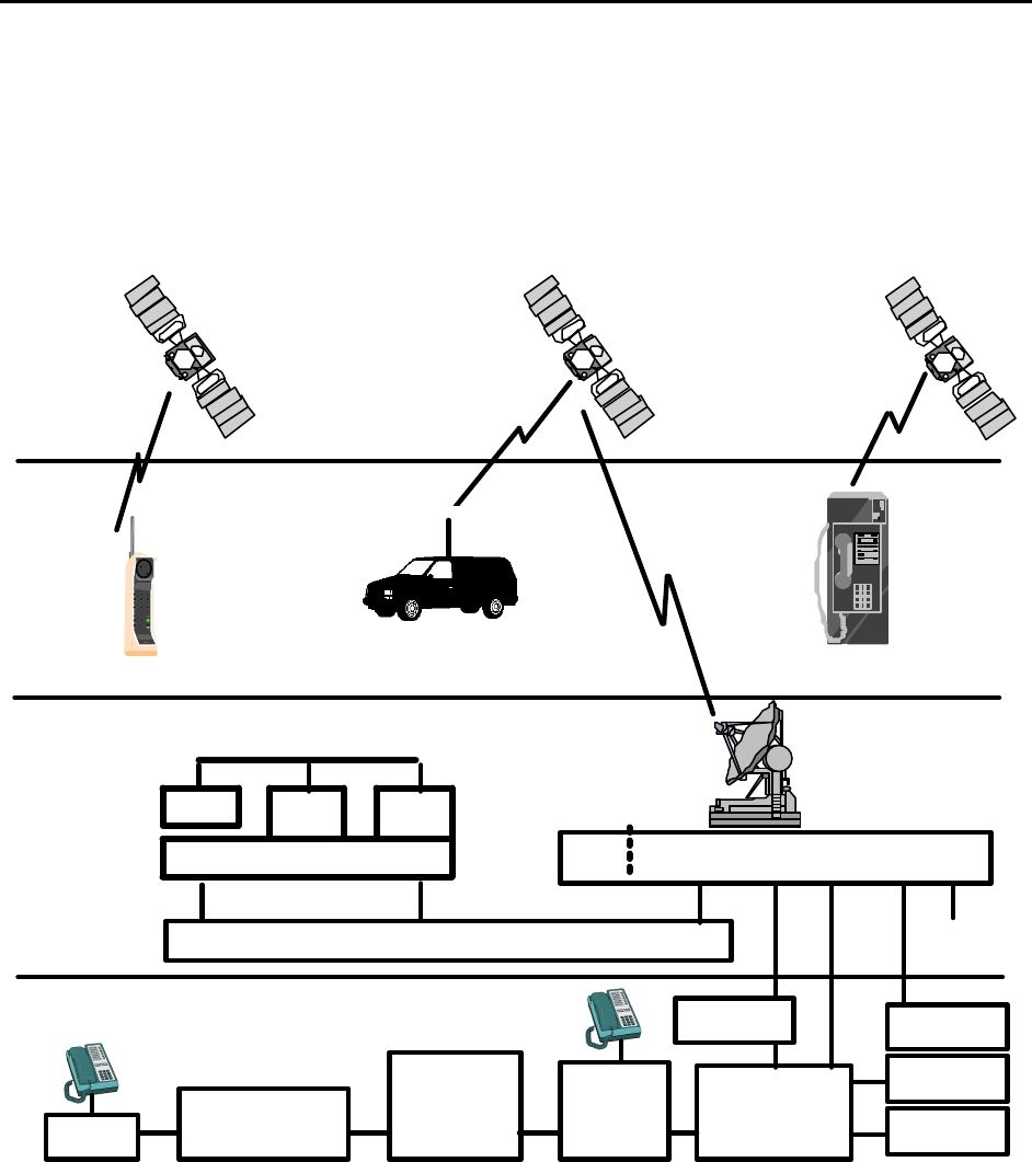
Terrestrial Network as shown in Figure 2-1.4
Satelli teSatellite
Space
Segme nt
Satelli te
S-Band Down Link
Fixe dMobil e
Segme nt
User
Portable
L-Band Up Link
Gateway
C-Band Down Link
C-Band Up Link
Gro u nd
Globalstar Data Network
Segme nt
Ter r estrial
Network
Long
D istan ce
Car r ier
Internatio na l
Carrier
PSTN/PLMN
PT T Private
Network
Cellular
Car r ier
Wirel in e
Telco
S P C C
GSM-MSC
TCU
GBO
GDN Interface
GO C C SOC C
LAN
CDA
5
Figure 2-1 Globalstar System Integrates with Terrestrial Network6
Description of the Globalstar System GS-TR-94-0001
Revision E
2-2
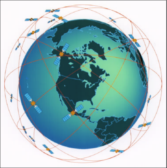
The Globalstar system provides communications from any point on the earth surface to any other point1
on the earth surface, exclusive of the Polar Regions as shown in Figure 2-2.2
3
4
5
6
7
8
9
10
11
12
13
Figure 2-2 Globalstar Constellation Serves Temperate Areas14
The satellite orbits are optimized to provide highest link availability in the area between 70 degrees south15
latitude and 70 degrees north latitude. Service is feasible in higher latitudes with decreased link16
availability. The Globalstar space segment consists of 48 satellites in 1410 km Low Earth Orbits. The17
low orbits permit low power hand sets similar to cellular phones. These satellites are distributed in 818
orbital planes with 6 equally spaced satellites per orbital plane. Satellites complete an orbit every 11419
minutes. User Terminals in a particular location on the surface of the earth are illuminated by a 16-beam20
satellite antenna as it passes over the earth.21
User Terminals can be served by a satellite 10 to 15 minutes out of each orbit. A smooth transfer22
process between beams within a satellite and between satellites provides unbroken communications for23
the users. The orbital planes are inclined at 52 degrees. Coverage is maximized in the temperate areas24
with at least two satellites in view, providing path diversity over most of the area. There is some small25
sacrifice in multiple satellite coverage at the equator and at latitudes above 60 degrees.26
The Gateways to the terrestrial network are illuminated by an earth coverage beam. The Gateway27
connects the User Terminal to the terrestrial network via the Gateway. The terrestrial network is not a28
part of Globalstar.29
Description of the Globalstar System GS-TR-94-0001
Revision E
2-3
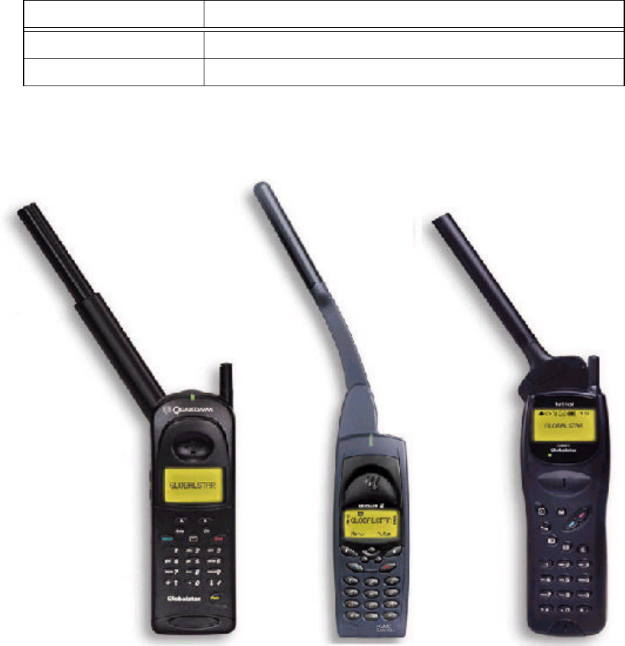
2.2 User Terminal1
The User Terminals come in several varieties. There are hand held units, mobile units and fixed station2
units. The available types of User Terminals are listed in Table 2-13
Table 2-1 Production User Terminals4
Fixed Terminal Hand Held and Mobile
Globalstar Only Dual Mode Globalstar & GSM
Tri Mode Globalstar & Terrestrial CDMA & AMPS
2.2.1 Hand Held and Mobile Units5
Typical hand held units are shown in Figure 2-3.6
Figure 2-3 Typical Hand Held User Terminal7
Qualcomm
Tri-mode
AMPS
CDMA
Globalstar
Ericsson
Dual-Mode
GSM
Globalstar
Telit
Dual-Mode
Globalstar
GSM
Description of the Globalstar System GS-TR-94-0001
Revision E
2-4
Globalstar Mode: Hand held User Terminals look like a standard cellular telephone. These are1
multiple mode handsets that operate with the local cellular system or Globalstar. The radiating element2
of the antenna is positioned above the head of the user. The antenna is positioned vertically to3
effectively utilize the symmetrical radiation pattern of the hand held antenna. The area next to the head is4
not used for radiation. This meets the safety requirements.5
Cellular Mode: When operating as a cellular mode handset, normal cellular operation can be6
expected. Cellular uses a separate and smaller antenna as is the custom with cell phones.7
Mobile - The mobile units consist of a hand held unit inserted in an adapter in the vehicle. The Mobile8
units typically have a higher gain antenna, a lower noise receiver and a higher RF power output. This is9
part of the adapter kit. The improved transmitter and receiver are mounted in the base of the antenna.10
The car kit that goes with a mobile typically includes:11
1. Hands Free Speaker and Microphone12
2. Outdoor Unit with a superior antenna13
3. Operation with the Vehicle battery14
Description of the Globalstar System GS-TR-94-0001
Revision E
2-5
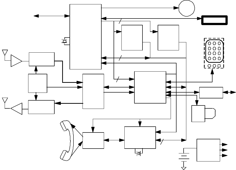
Block Diagram - Figure 2-4 is a simplified block diagram of the Globalstar portion of a User Terminal,1
which includes Globalstar/CDMA/AMPS.2
Figure 2-4 Globalstar User Terminal Block Diagram3
Since there is no hand off between the local cellular system and Globalstar, if the user crosses a service4
boundary between the local cellular system and Globalstar, the call could be dropped and must be5
placed again. The indicators tell the operator that the mode has changed.6
The system will not thrash in a boundary area. The user can select the preferred mode. If cellular is7
preferred and coverage is not available the UT will drop the call. The call can be placed in Globalstar8
mode. This call will continue until the phone is in an idle state. The reverse is also true.9
TLV320AV
Codec
Intel
386EX:
2 ch DMA
2 ch Serial
3 Timer/ctrs
Watchdog
Refresh ctl
Chip Sel unit
GUM ASIC:
rake receiver/
deinterlvr/dec
xmit
enc/interleave
dig FM , fart
123
456
789
*0#
LCD Display
BBII ASIC
TC554161
256K X 16
SRAM
28F016
1Meg X 16
Flash
TCXO &
Synths
Ringer
Address
16L Data
Diagnostic
Monitor
115.2K Serial I/O
ChipX8
10L Add
8 bit I&Q
Ref Clk
Tx IF
Sync & Clk
Power
Converter
5.0V PA
3.6Vaa
3.3Vdd
ADSP-2185L
Vocoder
7.2V
1.4AHr
S Band
Downconverter
L Band
Upconverter
Rx IF
Tx Antenna
Rx Antenna
Irq
Fr_Ref
8L Data
16.6 MHz Resonator
38.4K Serial I/O
Data
Port
RF Assembly
SM
Socket
RS-232
translator
49.152 MHz
Clock
LNA
PA
Description of the Globalstar System GS-TR-94-0001
Revision E
2-6
Function Performed : The start up functions of a User Terminal are programmable. As an example,1
when a dual-mode User Terminal first powers up it may attempt to log into the local cellular system.2
This addresses a scenario where the cellular system gets first priority to provide the service. If this fails3
the User Terminal then attempts to log onto the Globalstar system. Figure 2-5 illustrates a typical4
startup scenario within Globalstar.5
User Terminal
Control on the
Traffic Channel
State
Power-up
User Terminal has
fully acquired
system timing
Receives an
acknowledgment
to an Access
Channel
transmission
other than an
Origination
Message or a
Page Response
Message
Note: Not all state
transitions are shown. Directed to a Traffic Channel
Receives a Paging
Channel message
requiring an
acknowledgment or
response; originates
a call or performs
registration.
Ends use of
the Traffic
Channel
User Terminal
Initialization
State
User
Terminal
Idle State
System
Access State
6
Figure 2-5 User Terminal Startup Scenario within Globalstar7
The User Terminal looks for the best satellite pilot signal. When this is found it then switches to the sync8
channel and obtains the satellite database and other information. This database facilitates rapid9
Description of the Globalstar System GS-TR-94-0001
Revision E
2-7
acquisition of the pilot for any future calls. To place a call the user dials the number and presses1
"SEND". The User Terminal contacts the Gateway via the access channel. The Gateway and the User2
Terminal then work together to connect the call and support communications. Since the satellites are3
moving, the user is continuously being illuminated by different satellite beams or even different satellites.4
Diversity combining within the receivers supports a process of transferring traffic that is completely5
transparent to the user. The diversity combining process also provides better call reliability. The hand6
off process is accomplished without interruption to the call in process. If the user moves into an area7
that shadows or blocks access to one satellite, the space diversity link through a satellite that is not8
blocked maintains uninterrupted user communication9
2.2.2 Fixed Terminals10
Fixed station terminals are normally Globalstar only. The fixed User Terminals have a performance11
equivalent to the mobile terminal except that the antenna gain and transmitter power may be even higher.12
Fixed terminals do not require path diversity to combat fading and blockage. Fixed Terminals must13
support seamless beam to beam and satellite to satellite hand of14
15
16
17
18
19
20
21
22
23
24
25
Figure 2-6 Typical Fixed Terminal Application26
The fixed terminals can operate with a fixed phone, a payphone or other equipment.27
Gateway
Gateway
PSTN
Description of the Globalstar System GS-TR-94-0001
Revision E
2-8
2.3 Gateway1
The Gateways are geographically distributed by the service providers to serve their customer base.2
Figure 2-7 is a typical Gateway3
Figure 2-7 Typical Gateway Installation4
Gateways are designed for unmanned operation. A gateway consists of up to four 5.5-meter antennas5
as shown on the left and electronics equipment installed in a building or shelter as show on the lower6
right. In addition to the equipment racks, the facility supplied by the Service Provider includes prime7
power, an Uninterrupted Power System (UPS), as well as any maintenance or office facilities. The8
antenna layout is flexible. The major constraint is to place the antennas so that they do not block9
visibility of the satellite constellation. Safety considerations for the operating area must also be10
observed.11
Description of the Globalstar System GS-TR-94-0001
Revision E
2-9
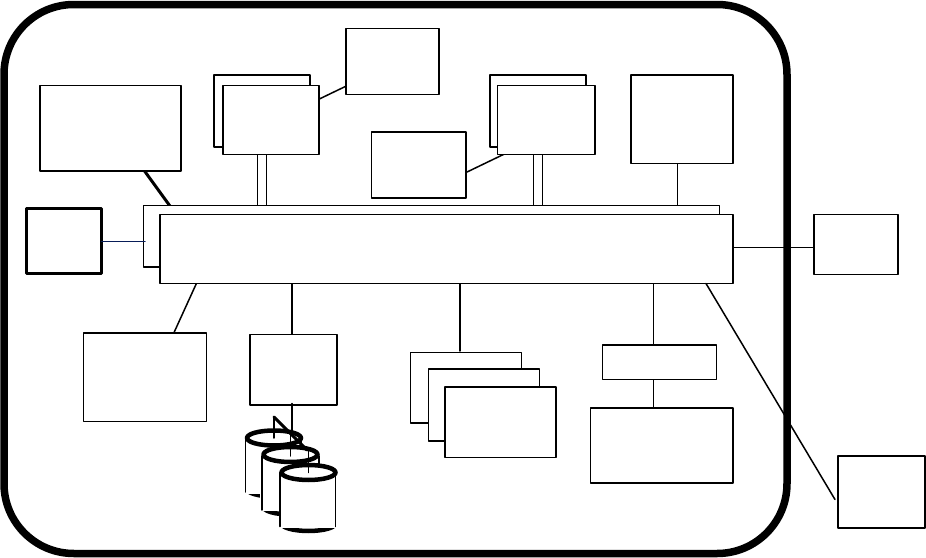
Figure 2-8 is a simplified block diagram of a typical Gateway.1
Figure 2-8 Gateway Simplified Block Diagram2
Appearance : The Gateway consists of up to four identical parabolic antennas that are at least 5.53
meters in diameter. The antenna structure contains drive mechanisms for positioning the antenna, low4
noise receivers and high power transmitters. The antenna structure may be enclosed in a Radome to5
provide protection from the environment.6
The antennas connect to a building that houses the electronics equipment. The Code Division Multiple7
Access (CDMA) equipment, PSTN interface equipment that interfaces with the terrestrial telephone8
network, and computer equipment to operate the Gateway and collect status and performance data are9
located in the electronics facility.10
Function Performed : The Gateway supports voice communications, paging, and data transmissions.11
Position location services are also supported.12
The Globalstar Gateway connects the Globalstar space segment to terrestrial switching equipment. The13
Gateway receives telephone calls from the terrestrial switching equipment and generates Code Division14
Multiple Access (CDMA) carriers to transmit through the satellite. The satellite then re-transmits the15
signal to User Terminals. These User Terminals may be either hand held, fixed or mobile and located16
anywhere within the satellite antenna footprint.17
SPCC GW Links E1 or T1
BCN MSSL
Ethernet
IFL
PSTN
SSA
Patch Panel
CSUNIS
GWRDB
VLR
Patch Panel
Patch Panel
BSCI GSM
MSC
VLR
T1/E1
Trunks
SBS
CIS
(DISCO)
GTS
RL
TFU
GPS Rcvr
Router
SPCC Router
GDN
FL
7 56
12
11
10
8 4
2
1
9 3
Up Converter
SSPA
RL
LNA
Down
Converter
Antennas
(up to 4)
TCU Panel
TCU
TCU
TCU
TCU
GSS
(Gateway Switching System)
GCS
(Gateway CDMA System)
GMS
(Gateway Management System)
GOCC
SOCC
TCU
(Telemetry & Command Unit)
ROPI
GRS
(Gateway RF System)
Digital
Cabinets
(up to 13)
Demod
Cards
FL Cabinet
RHCP
LHCP
RHCP
LHCP
GSM
HLR
IS-41
HLR
E1
Trunks
SS7
SS7
SS7
VME
Backplane
Common
Card
Receive
Cabinets
(up to 13)
Receiver
Cards
Controller
Card
SBS Shelf
1/96 calls
Selector
Cards (12)
Interface
Card
ΣΣ
GCU
T1
FL Shelf
(40)
5/polarize/ant
Upconverter
Cards
Modulator
Cards
GDN Router
1
4
7
*
2
5
8
0
3
6
9
#
DGlobalstar
DIGITAL BY
ABC
TFU
Cabinet
(2)
Splitters
TFU
Cabinet
(2)
Splitters
1
4
7
*
2
5
8
0
3
6
9
#
ON OFF
D
Globalstar
DIGITAL BY
VME Cage
CCP
VME Cage
GWC
VME Cage
SS7
Server
CDA
VIP
2
1
3
Trunk Set Combinations
(most likely):
· IS-41 territory:
· GSM territory:
T1
1 2
2 3
OMC
GM
OPI
Description of the Globalstar System GS-TR-94-0001
Revision E
2-10
In the return direction, the User Terminal transmits to the satellite(s) and the satellite(s) re-transmit the1
signal to the Gateway. The Gateway connects the call to terrestrial switching equipment, which can then2
connect to any subscriber using the standard telephone system. Connections can also be made to3
terrestrial cellular subscribers or to other Globalstar User Terminals.4
The Gateways are designed to operate without operator intervention. Maintenance is performed by5
service provider personnel as required. Status may be remotely monitored by the Service Provider's6
Control Center (SPCC).7
Functions of the major elements of the Gateway are listed below.8
Telemetry and Control Unit (TCU): The TCU acts as a telemetry and control interface between the9
satellite constellation and the SOCC. The TCU interfaces with the SOCC via the router in the GMS.10
The TCU interfaces with individual satellites via the GTS and the GRS.11
Gateway RF Subsystem (GRS): The GRS interfaces the gateway to Globalstar users via the12
Globalstar satellite constellation.13
Gateway Management Subsystem (GMS): The GMS interfaces the gateway with external14
management entities (SPCC). The GMS performs non-real-time configuration and management of the15
gateway.16
Call Detail Access (CDA): The Call Detail Access (CDA) is a separate, fault-tolerant workstation17
within the GMS, with stricter reliability requirements than the rest of the GMS. The CDA uses a18
confirmed-transfer protocol to retrieve accounting from the SBS, CCP and GC.19
CDMA Subsystem (CS): The CS performs real-time operation of individual calls, maintaining the20
integrity of each physical link and performing physical layer format conversion between the CDMA21
wave form on the GRS side and PSTN signals on the GSS side.22
Gateway Controller (GC): The GC is responsible for operation and supervision of the CS and of the23
GRS.24
Gateway Transceiver Subsystem (GTS): The GTS is responsible for the physical layer25
implementation of the Globalstar Air Interface. Under the control of the GC, control elements in the26
GTS set up and operate overhead and traffic channels as required.27
CDMA Interconnect Subsystem (CIS): The CIS provides packet-level and timing reference28
connectivity between all subsystems in the gateway.29
Selector Bank Subsystem (SBS): The SBS provides an interface between the SSA and the CS, and30
performs layer two operation and radio link management of individual traffic channel circuits. The SBS31
also performs service option-specific processing of traffic channel data. Service options may include32
voice, data, and short message services.33
Description of the Globalstar System GS-TR-94-0001
Revision E
2-11
Base Station Controller Interface (BSCI): the BSCI provides an interface between the CDMA1
Subsystem (CS) and the GSM MSCs. The BSCI implements the BSC side of the A1 Interface,2
providing the SS7 transport, the protocol discrimination function, BSSMAP processing, and passes the3
DTAP messaging between the GSM MSC and the CS. The BSCI can be configured to terminate4
multiple A1 Interface links between multiple GSM MSCs. The configuration and setup of the BSCI is5
controlled through the GMS interface (by way of the CS).6
Time and Frequency Unit (TFU): The TFU provides a highly reliable and stable source of timing and7
frequency references to the CS and to the GRS. The TFU output is synchronized to the Global8
Positioning System (GPS).9
Gateway Switching Subsystem (GSS): The GSS interfaces the gateway to the PSTN and controls10
the state of each call.11
Separation of CDMA & Switch: Although not often done, it is technically feasible to separate the12
Selector Bank Subsystem from the switch equipment. The interface between the two elements is an13
unformatted T1. Communications Service Units (CSUs) could be used at this point to separate the14
switching subsystem from the remainder of the gateway.15
Description of the Globalstar System GS-TR-94-0001
Revision E
2-12
2.4 User Terminal and Gateway Interaction1
Hand Off: The moving satellite constellation requires hand off to different satellites and to different2
beams. In general, hand off is transparent to the user. Hand off on the forward link does not imply3
hand off on the return link.4
Forward Link: In the forward link direction (from the Gateway to the User Terminal), hand off is5
totally under control of the Gateway. The User Terminal finds pilots and reports quality to the Gateway.6
When a second pilot is seen, the quality is reported to the Gateway. If the Gateway determines that it is7
advisable, the Gateway will instruct the User Terminal to incorporate the signal into the diversity8
combiner. At all times the user terminal is using a fast algorithm to search for other pilots. Once a9
suspected pilot is detected, it is turned over to one of the fingers used as a clincher. So at one point in10
time, the User Terminal may have 3 fingers active. One is the traffic finger, one is used for diversity11
combing and the third finger is used as the clincher. In the forward direction the role of the User12
Terminal can be summed up as the proposer. The Gateway can be viewed as the disposer. The User13
Terminal suggests which pilots should be used. The Gateway decides.14
Return Link: In the Return Link direction, the Gateway uses up to 6 fingers. Eb/No is measured. If15
the Eb/No is above a usable threshold it is added into the diversity combiner multiplex. New signals are16
added in until the Gateway runs out of fingers. A stronger signal will not cause the Gateway to take a17
weaker signal out of the diversity combining process as long as it is above the threshold. Once a signal18
drops below the acceptable threshold, it will be taken out of the diversity combining process and the19
finger released for assignment to other incoming User Terminal signals.20
Soft Hand Off: In soft hand-off, two or more received signals through different links are simultaneously21
demodulated, combined, and decoded by the same entity. It is characterized by commencing22
communications using a new pilot on the same CDMA frequency before terminating communications23
with the old pilot. This is a hand off occurring while the user terminal is operating on the Traffic24
Channel.25
Hard Hand Off: In hard hand off, the receiving entity stops demodulating and decoding information26
transmitted on one link and starts demodulating and decoding information transmitted on another link27
with possible loss of information. A hard hand off is characterized by a temporary disconnection of the28
Traffic Channel. Hard hand off occur when the user terminal changes frequency or frame offsets. The29
“temporary disconnect” does not mean the call is dropped. There is sufficient hysteresis in the system30
to avoid dropping the call.31
Access Channel: The access channel is slotted aloha (TDMA). It does not use diversity. This channel32
is activated by the User Terminal to contract the gateway in the event the User Terminal is attempting to33
initiate a call.34
Description of the Globalstar System GS-TR-94-0001
Revision E
2-13
2.5 Globalstar Control Centers1
There are two operations control centers. Each is completely capable of operating the network and2
managing the satellite constellation. There are two to circumvent the possibility of earthquake, power3
grid failure or other disaster. One is located in San Jose, California and one is located near4
Sacramento. Each includes:5
1. Ground Operations Control Center.6
2. Satellite Operations Control Center7
3. Globalstar Business Office8
The integrated control center is shown below in Figure 2-99
10
11
12
13
14
15
16
17
18
19
20
21
22
Figure 2-9 Globalstar Control Center23
Description of the Globalstar System GS-TR-94-0001
Revision E
2-14
2.5.1 Ground Operations Control Center1
Ground Operations Control Centers (GOCC) are responsible for planning and management of the2
communications resources of the Globalstar satellite constellation. This is coordinated with the Satellite3
Operations Control Center (SOCC). Figure 2-10 illustrates how the Ground Segment Equipment4
operates together to support Globalstar Communications Functions.5
• Relays communications
•
R
e
l
a
y
s
s
i
g
n
a
l
l
i
n
g
f
r
o
m
g
w
t
o
u
s
e
r
s
• Relays signalling from user to gw
– Access request
– Power change request
– Registration
C-BAND
– pilot– paging – ephemeris update
– synch– power control
• signalling
• voice & data communications
• multi-mode - including cellular
L-BAND
(return)
S-BAND
(forward)
Globalstar Data Network (GDN)
Ground Operations
Control Center
(GOCC)(SOCC)
• connect user to switch
• data for billing
– signalling
– voice & data comm
• manage within resources
Gateway
(GW)
• Provides orbits
• Satellite health
• Battery state
• Selects filters
• Sets gains
Real Time• allocate resources
– satellite
– gateway
• monitor performance
• generate traffic plans
Planning
File: CommFunc
Satellite Operations
Control Center
- Downloads
6
Figure 2-10 Ground Segment Support for Communications7
The GOCC and the SOCC may be collocated or they may be physically separated with linkage via the8
Globalstar Data Network as shown in Figure 2-10. If the two are collocated, the connection will be by9
a Local Area Network (LAN). In either case, the GDN connections are required to accommodate10
failure scenarios. These collocations will reduce long term personnel costs since both the GOCC and11
the SOCC are manned facilities.12
Figure 2-11 is a simplified block diagram of the Ground Operations Control Center (GOCC)13
Description of the Globalstar System GS-TR-94-0001
Revision E
2-15
Local Area Network
(redundant)
4 mm
Tape
Subsystem
Management
Applications
Systems
Admin.
Console
File
Server
Large Screen
Display
Processor
Work
Stations
Operations
Remote
Display
Local
SOCC
GDN
High
Performance
Computer
Resource
Allocation
Work
Stations
Remote
Display
Backups and
Archives
Printers &
Scanners
Visitor
Display
Disks
GPS
Rcvr
1
Figure 2-11 GOCC Simplified Block Diagram2
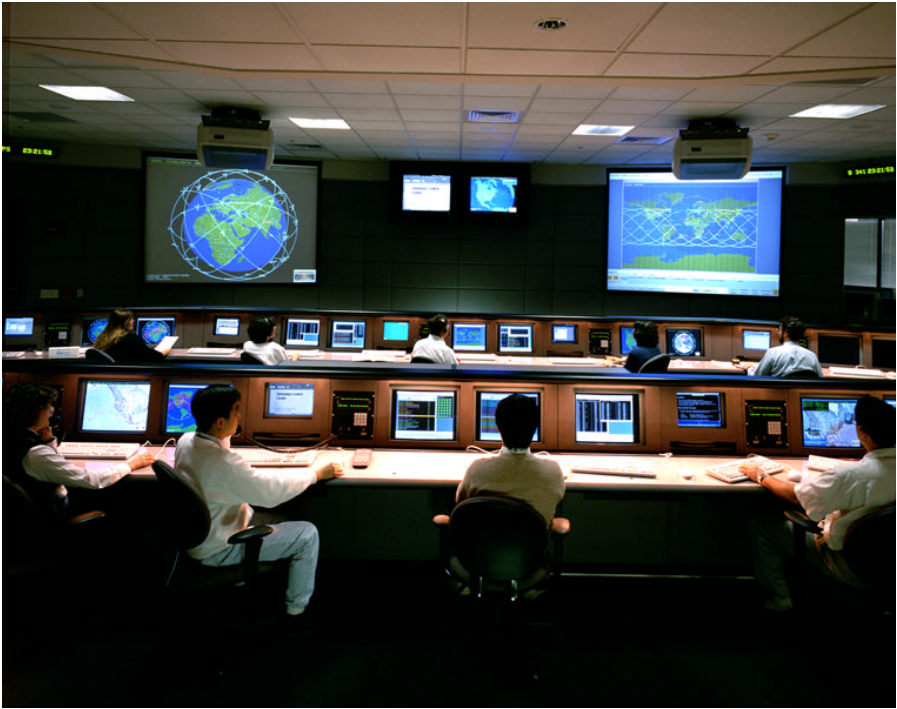
In addition to the planning functions, the GOCC is responsible for monitoring performance and ensuring3
that the Gateways remain within the allocated satellite resources.4
Appearance: The Ground Operations Control Center consists of a number of workstations in a5
control center environment. Besides the workstations used by the operators, there are other displays in6
the control center.7
1. There are large screen remote displays located in the area. The computer operators can8
project any of the screen displays onto the large screen displays and continue operations. The9
large screen displays will update as the status changes.10
2. There is also a large display that shows the position, coverage and status of the space11
segment.12
3. A separate animated communications network display indicates the number of circuits flowing13
through Globalstar and indicates any congestion or circuit outages.14
Function Performed: The Ground Operations Control Center (GOCC) is the planning element for the15
Globalstar communications system. The redundant GOCCs plan the communications schedules for the16
Gateways and control the allocation of satellite resources to each Gateway. The Gateways process real17
time traffic within these assigned resources. The GOCC incorporates facilities to:18
Description of the Globalstar System GS-TR-94-0001
Revision E
2-16
1. Generate long-range plans based on projected traffic requirements and constraints such as1
available frequencies, Gateway capacities, service areas, etc.2
2. Monitor usage and refine plans based on measured performance of the system and3
constraints imposed by the SOCC.4
3. Report satellite usage to the Satellite Operations Control Center.5
The GOCC facilities are operated 24 hours per day.6
Emergency Power: Critical elements of the ground equipment require a no-break power source or7
some form of backup power.8
9
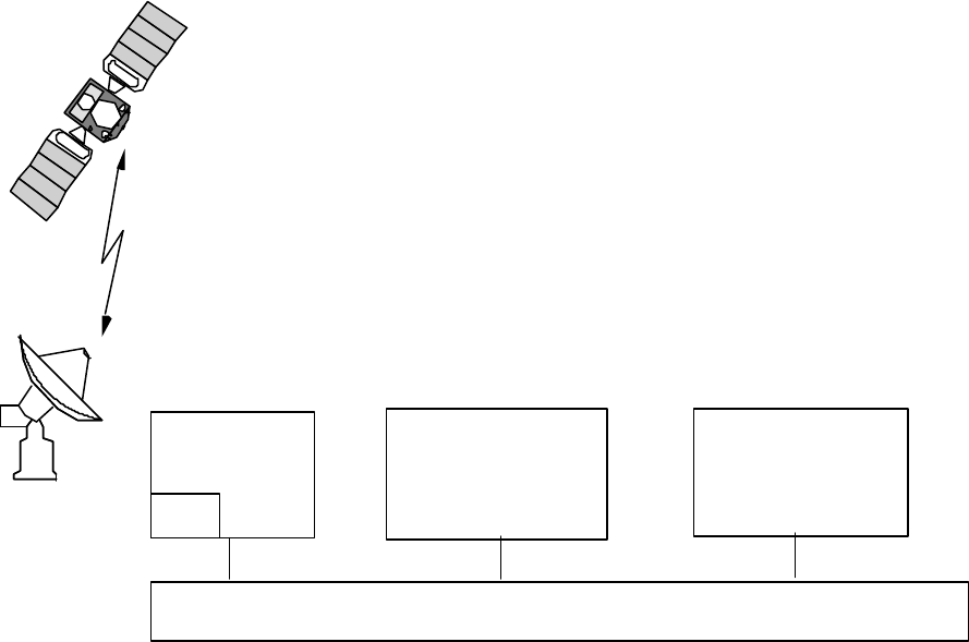
Description of the Globalstar System GS-TR-94-0001
Revision E
2-17
2.5.2 Satellite Operations Control Center1
The Satellite Operations Control Center (SOCC) manages the satellites. Redundant SOCCs control2
the orbits and provide Telemetry and Command (T&C) services for the satellite constellation. In order3
to accomplish this function on a worldwide basis, the SOCC communicates with T&C units collocated4
at selected Gateways. The T&C units share the RF links with the Gateway communications equipment5
to relay commands and to receive telemetry. Figure 2-12 illustrates how the various elements of the6
Globalstar Ground Segment operate together to support the command and telemetry functions.7
• T ransmit satellite telemetry
• R eceives & acts on commands
– D ecrypts
– S tores if time tagged
C-BAND
Globalstar Data Network (GDN)
• A llocates satellite
Tracking schedules
resources to GWs
• P rovides gateway
(GOCC)
• M onitors telemetry
• E ncrypts commands
• O rbit determination
• I nforms GOCCs
– S atellite available
– S atellite capacity
– S atellite ephemeris
(SOCC)
• S ends commands
• R eceives telemetry
• T racks satellites
– P rogram track
Gateway
(GW)
TCU
File: ContFunc
Ground Operations
Control Center
Satellite Operations
Control Center
8
Figure 2-12 Ground Equipment Support for T&C Functions9
Telemetry Down link and Command Up link: Globalstar satellites continuously transmit telemetry10
data, which contains orbit position data and measurements of current on-board health and status of the11
spacecraft. Because both the telemetry stream and the communications payload feeder links will utilize12
C-band communications, T&C operations utilize antennas and RF-equipment at selected13
communications Gateways. Since only selected Gateways have T&C units, telemetry is available only14
when an antenna with a T&C Unit is tracking the satellite. All Gateways equipped with T&C Units15
have the ability to command the satellite. The T&C unit consists of special purpose RF cards and a16
DSP controlled by a Pentium based Personal Computer. A single self-contained rack will17
accommodate up to 5 T&C Units (1 spare). The T&C units are designed to run automatically, with18
Description of the Globalstar System GS-TR-94-0001
Revision E
2-18
control from the SOCC. Routine staffing is not required. Any maintenance will be provided by service1
provider personnel dispatched on call from the Globalstar Control Center (GCC).2
Telemetry Reception: Telemetry from each satellite will be received at the T&C Gateway that have3
an antenna trained on that satellite. The T&C unit will be able to either directly send the demodulated4
data (bent-pipe mode) or store it for later transmission (store and forward mode). Stored data will be5
sent to the SOCC upon SOCC request, typically during a period of lower system utilization or lower6
communications network costs. The SOCC will coordinate the T&C data transmission to avoid7
receiving identical data sets from multiple T&C sites. The telemetry data sent from the T&C site is8
routed to the SOCC as packet messages on the Globalstar Data Network (GDN). Should more than9
one SOCC be providing support, the T&C equipment will route the data to multiple destinations.10
Command Transmission: Commands received from the SOCC are immediately transmitted to the11
satellite (bent pipe mode only). Depending upon the command, the satellite can execute the command12
immediately or store the command for execution at a later time. The TCU does not incorporate a13
command storage facility. The SOCC is responsible for directing the command message to the proper14
T&C at the correct time for transmission.15
SOCC Operations: The SOCC will receive minor frames over the Globalstar Data Network. Data16
received in the telemetry bent-pipe mode is immediately routed to the user workstations assigned to17
monitor or control the specific satellite. At any one time, all satellites in contact are automatically18
monitored by the software, with only selected satellites directly monitored by a member of the flight19
operations team. A single workstation can monitor up to 6 satellites. An operations controller may20
have asked for up to 6 specific satellites to monitor or may have defined the criteria by which the system21
can automatically determine which satellites are to be monitored. For example, the controller could22
request to see all satellites for which real-time data is being received for which the power subsystem23
monitoring software detects a possible area of concern.24
Because of the very low telemetry rates, it is possible to have remotely located workstations, connected25
to the SOCC via simple modem or ISDN communications. A workstation at the satellite26
manufacturer's facility, for example, could routinely be used to monitor a single satellite to support27
problem investigation, routine monitoring, or analysis.28
The SOCC is also responsible for coordinating activities with the GOCC. The three primary interface29
functions are:30
a. Orbit position information: The SOCC will provide information to the GOCC so that each31
Gateway can accurately track each satellite. The data will consist of data tables sufficient to allow the32
Gateway software to generate its own contact lists.33
b. Utilization statistics: The GOCC will provide statistics to the SOCC pertaining to the actual34
communications quality and utilization (Gateway assessment) of each satellite. This information will be35
correlated with satellite telemetry to distinguish between expected and anomalous behavior.36
Description of the Globalstar System GS-TR-94-0001
Revision E
2-19
c. Spacecraft status: The SOCC will report to the GOCC spacecraft/transponder availability. This1
data will include limitations associated with any satellite, which may constrain or preclude its use for2
communications.3
Use of Multiple SOCCs : Two SOCCs are planned. The San Jose, California location will support4
primary operations and a second one in El Dorado Hills, California serves as a backup to the prime.5
Both SOCCs will be able to receive telemetry data from the same satellites so that dual-site monitoring6
and "hot backup" functions could be supported; however, the baseline is a single string SOCC7
operation.8
The main reason for the second SOCC is to create a backup operational facility in case of a9
catastrophic failure (fire, etc.) at the primary site. The two SOCCs, however, could be used routinely10
to share the load between two sites, to conduct training and to support development and test of11
software upgrades.12
2.5.3 Globalstar Business Office13
To support the Globalstar Business Office (GBO), the Globalstar Accounting & Billing System (GABS)14
is collocated with the GOCC and the SOCC. The GABS is responsible for all financial activities15
associated with Globalstar.16
Appearance: The GABS is a client/server system with many workstations and the requisite office17
facilities required to support the assigned accounting and billing activities. The server for the primary18
GABS is located in the GCC. A back-up GABS server is located in the alternate GCC. Multi-19
platform client support is provided.20
Functions: The GABS provides basic accounting and billing functions for GLP. The accounting21
functions are provided by a Commercial - Off - The - Shelf (COTS) package, ORACLE Financial, and22
include accounts payable, accounts receivable, general ledger, purchasing , and financial planning23
software. The wholesale billing function, provided by custom developed software, receives data from24
both the Gateways and the Service Providers. These data, call usage summaries, subscriber counts,25
etc. are used to calculate charges for usage of the Globalstar system and to generate bills which are sent26
to the service providers monthly.27
Description of the Globalstar System GS-TR-94-0001
Revision E
2-20
2.6 Globalstar Satellite1
The Globalstar satellite is a simple low cost satellite designed to minimize both satellite costs and launch2
costs. A pictorial of the satellite and some of the major characteristics are shown in Figure 2-13.3
RELIABILITY
• Ps = 0.85 for 7.5 years, providing
15 of 16 beam pairs
AUTONOMY
• FDIR
• Safe Mode (Earth & Sun)
TELEMETRY & COMMANDING
• C-Band CMD/TLM - 1.0 KBPS
• Real Time, Stored and Macro
• CMD Encryption - KI - 23
• <500 Hardware Commands
• <500 Hardware Telemetry Items
ORBIT DETERMINATION
• GPS Tensor (<90 M. Semi-Major Axis)
ATTITUDE DETERMINATION ( 0.7 half cone)
• Earth Sensor
• Magnetometer
• 3 Sun Sensors
ATTITUDE CONTROL (NORMAL)
• Yaw steering & Momentum Bias
• 4 Reaction Wheels
• Mag. Torquer along X&Y
STRUCTURE
• Rigid Al Frame
• Al Honeycomb Panels
MASS
• <450 kg (Wet)
ELECTRICAL POWER
• 1.1 kW EOL Solar Array
• Single-Axis Track(Rotate)
• Peak Power Tracker
• 14-23 V Unregulated Bus
• Ni- H2 Battery, 14 Cells, 64 Ah
THERMAL
• Generally Passive
• Heat Pipes
• Thermostatic Control Heaters
PROPULSION
• Mono-Hydrazine (76.6 kg)
• Blow Down Regulation (4:1)
• Passive Management Device
• 5-1 Newton Thrusters
ON-BOARD PROCESSING
• 1750 A
• 16 BIT, 1.8 MIPS, 64K SRAM
& 128K PROM
• 16K SUROM
• RS422 & RS485 I/O
• ADA
• 8K Safeguard Memory (SGM)
4
Figure 2-13 Spacecraft Bus Characteristics - Highly Autonomous5
Communications Payload : A pictorial of the communications payload is shown in Figure 2-14.6
Description of the Globalstar System GS-TR-94-0001
Revision E
2-21
MASS
COMMUNICATIONS CHANNEL
S-BAND ELECTRICAL POWER
TELEMETRY & COMMANDING
Beam Configuration (L - Band)
• <154 kg
• Each channel is 16.5 MHz with
• 16 total channels
• 1 channel per beam
19.38 MHz centers
• Continuously
Payload senses SSPA input power
level and adjusts transmit power
• Dedicated high efficiency
• C-Band for command & telemetry
• Telemetry 1 of 12 selectable
carriers uniformally spaced
• Single command frequency with
unique satellite ID
• Generally Isoflux
• 16 Beams
• 1 - Central Beam 22.5 deg
• 15 - Outer Beams to 54 deg
COVERAGE (ALL BANDS & ANTENNA)
• Satellite to User
• Active Phased Array
• 91 Elements
• Frequency = 2483.5 to 2500 MHz
• Max. SSPA RF 4.2 Watts
• User to Satellite
• Active Phased Array
• 61 Elements
• Frequency = 1610 to 1626.5 MHz
• Scalar Horn
• Bi-Polarized, 8 channels per
Transmit Freq. = 6875 to 7053 MHz
Rec. Freq. = 5091 to 5250 MHz
• Fill subtended angle = 108 deg
(with respect to satellite nadir)
S-BAND TRANSMIT ANTENNA
L-BAND RECEIVE ANTENNA
C-BAND XMT/RECEIVE ANT.
Beam Configuration (S-Band)
• Generally Isoflux
• 16 Beams
• 1 - Central Beam Radius 16 deg
• 6 - Middle Beams to 37 deg
• 9 - Outer Beams to 54 deg
1
Figure 2-14 Communications Payload Pictorial2
The communications payload is a simple bent pipe communications package as shown in Figure 2-15.3
MASTER FREQUENCY
GENERATOR
RETURN TRANSPON DER
FORWARD TRANSPONDER
FREQUENCY CONVERSION SECTION
FREQUENCY CONVERSION SECTION
FORWARD
LINK FROM
GATEWAY
RETURN
LINK TO
GATEWAY
L-C BAND
C-S BAND
C BAND
SSPA
C BAND
LNA
L-BAND RX
ACTIVE
ANTENNA
S-BAND TX
ACTIVE
ANTENNA
FORWARD
LINK TO
USER
RETURN
LINK FROM
USER
File: Sat Comm
SAW
SAW
SAW
SAW
S
W
I
T
C
H
S
W
I
T
C
H
D
I
P
L
E
X
E
R
TLM
D
I
P
L
E
X
E
R
CMD
4
Figure 2-15 Communications Payload Simplified Block5
Function Performed : A User Terminal transmits to the satellite by L-Band. The signal enters the6
satellite through the L-Band low noise amplifier. It is amplified and then converted into a C-Band signal7
Description of the Globalstar System GS-TR-94-0001
Revision E
2-22
after which it is further amplified. This is radiated to the Gateway. The Gateway receives the signal and1
block down converts to an intermediate frequency. A sample of the intermediate frequency is provided2
to the TCU for processing. The communications traffic is presented to the CDMA equipment for3
demodulation.4
In the forward link direction, the Gateway combines the up link CDMA signals with the signal from the5
command transmitter and radiates it at C-Band up to the satellite. The satellite then down converts the6
signal and radiates an S-Band down link signal to the User Terminals.7
Telemetry & Command : The Telemetry and Command carriers share the C-Band with the8
communications feeder links. Figure 2-16 is a simplified block diagram of the T&C package on the9
satellite.10
ReceiverDC/DC
Command
ReceiverDC/DC
Command RS-422
RS-422
OBPE
AE CMD Filter
LNAs
Telemetry
Encoder
TLM channel
Insertor
Data (Manchester)
RS-422
Telemetry
TransmitterDC/DC
Telemetry
TransmitterDC/DC
Telemetry
Encoder
Data (Manchester)
O
B
P
E
From
C-Band
SSPAs
Output Filter
(LHCP)
AE TLM Filter
RS-422
AE TLM Antenna
Command
Decoder
Command
Decoder
Data (NRZ-L)
Clock
Squelch
Data (NRZ-L)
Clock
Squelch
To
C-Band LNAs
(LHCP)
Input Filter
CMD Channel
Extractor
AE CMD Antenna
11
Figure 2-16 Satellite T&C - Compatible with Communications12
The T&C connects to the normal C-Band communications antenna for on-orbit operations. There is13
also a T&C antenna on the anti-earth face of the satellite. This antenna functions when the satellite is not14
Description of the Globalstar System GS-TR-94-0001
Revision E
2-23
oriented correctly or when there are problems. The anti-earth antenna is to ensure that telemetry can be1
obtained and commands entered under all recoverable contingencies. Note that the anti-earth antenna2
bypasses the Low Noise Amplifier. This means that the transmitted power from the commanding earth3
terminal will have to be higher than the normal power required for commanding. This can be4
accommodated because there is no communications traffic when the satellite is not oriented correctly.5
Yaw Steering: The satellite is steered in yaw to keep the solar panels oriented toward the sun to6
extract the maximum energy. This increases the communications capacity of the Globalstar System.7
There are some minor penalties that cause a slightly slower acquisition time and may cause more hand8
offs than would be otherwise required.9
Description of the Globalstar System GS-TR-94-0001
Revision E
2-24
This page intentionally left blank.1
2
Description of the Globalstar System GS-TR-94-0001
Revision E
3-1
3. FREQUENCIES AND COVERAGE ANALYSIS
1
3.1 Frequency Plans
2
Globalstar uses C-Band between the Gateway and the Satellites as shown in Figure 3-1.3
5250 MHz
91113158 3 7 5
12 14 16 10 1 6 4 2
C
m
d
LHCPS-Band
2500 MHz2483.5 MHz
5091 MHz
LHCP
16.5 MHz 19.38 MHz
RHCP
16.5 MHz
16 BEAMS
159 MHz
TO USER TERMINAL
Satellite Transponder
7055 MHz
LHCPL-Band
6875 MHz
LHCP
180 MHz
TO GATEWAY
16.5 MHz
1610 MHz 1626.5 MHz
T
L
M
Satellite Transponder
RHCP
31513115 9 716
81046 14212
Beam
Beam
Beam
X1 X2 X3 X4 X5 X6 X7 X8 Channel
Y1 Y2 Y3 Y4 Y5 Y6 Y7 Y8 Channel
X1 X2 X3 X4 X5 X6 X7 X8
Y1 Y2 Y3 Y4 Y5 Y6 Y7 Y8
Channel
FROM GATE WAY FROM UT
File: Freq Plan
1
4
Figure 3-1 Frequency Plan - Emphasizes Conservation of Spectrum
5
The C-Band antennas on the satellite use an earth coverage beam. The Gateways use a parabolic6
antenna and program track the satellites. Program tracking uses the orbital data provided by the7
Satellite Operation Control Center to position the Gateway antenna.8
Efficient Spectrum Utilization - The spectrum is used efficiently by incorporating frequency9
reuse and spread spectrum into the design. Both Right Hand Circular Polarization (RHCP) and10
Left Hand Circular Polarization (LHCP) are used for C-Band. This allows 8 frequencies to11
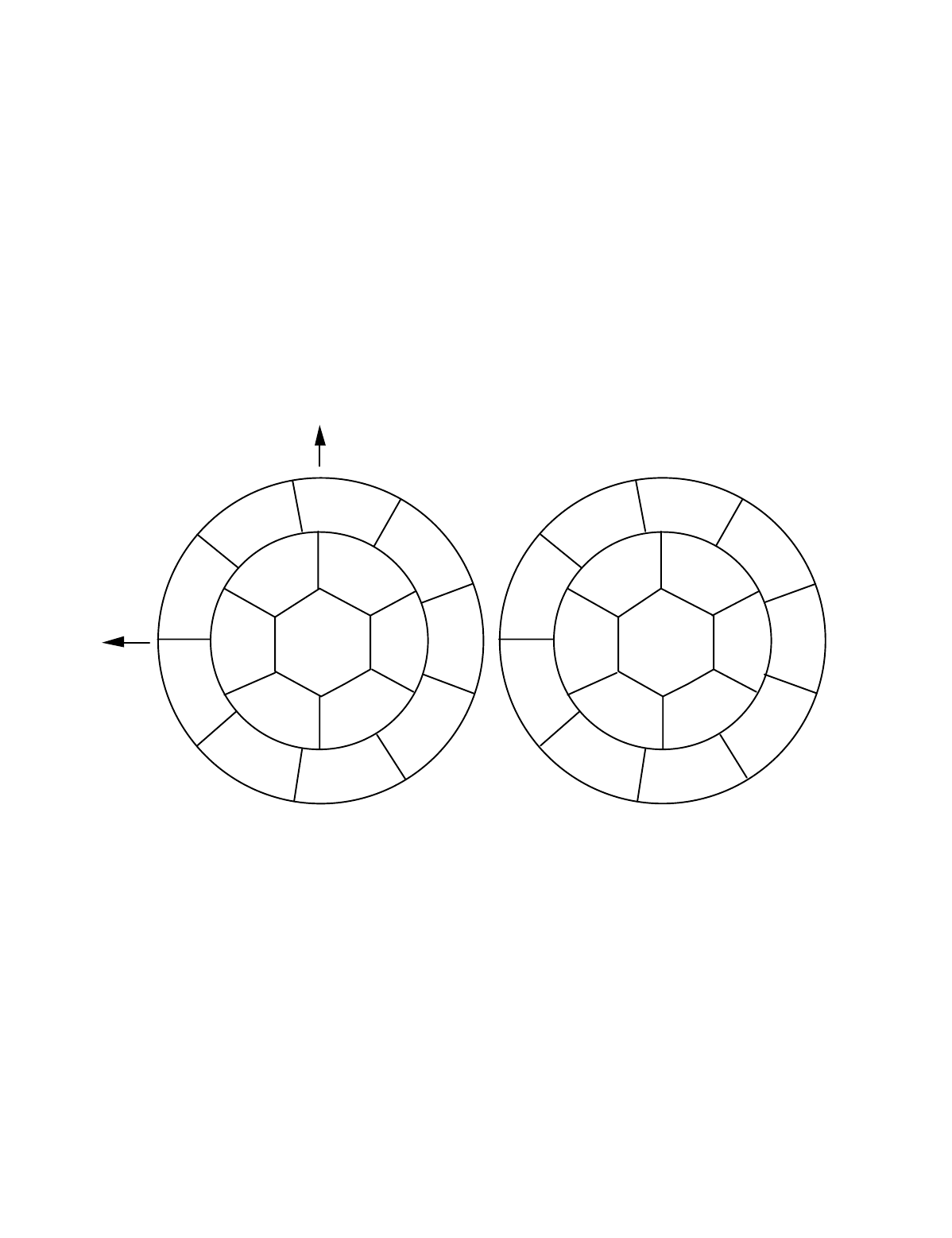
Description of the Globalstar System GS-TR-94-0001
Revision E
3-2
connect to 16 beams on the satellite. The beam numbers shown in Figure 3-1 map to the S-Band1
beams shown in Figure 3-2 and the L-Band beams in Figure 3-3 which follows. The alpha2
characters used within the spectrum blocks and on the following diagram indicate polarization.3
X= Left Hand Circular Polarization4
Y= Right Hand Circular Polarization5
3.2 Satellite Antenna Beam Configuration
6
The S-Band antennas on the satellite are configured to produce 16 beams as shown in Figure 3-7
2.8
8
9
10
11
1213
14
15
16
1
2
3
45
6
7
+Xsc
+Ysc
Y5
Y1
X4
Y2
X1Y3
X2
Y4
X3
X5
X8
Y6
X7 Y8
X6
Y7
File: S-Beams
Channel Assignments Beam Assignments
View from Satellite
X= LHCP
Y=RHCP
Looking at Earth Nadir
9
Figure 3-2 S - Band Beams
10
The antennas are multiple beam antennas designed to provide an isoflux pattern on the earth in11
the service region. The isoflux pattern is obtained by shaping the beam so that the gain at the12
edge of coverage is higher than at the beam center. This compensates for the difference in losses13
due to the longer slant range at the beam edges.14
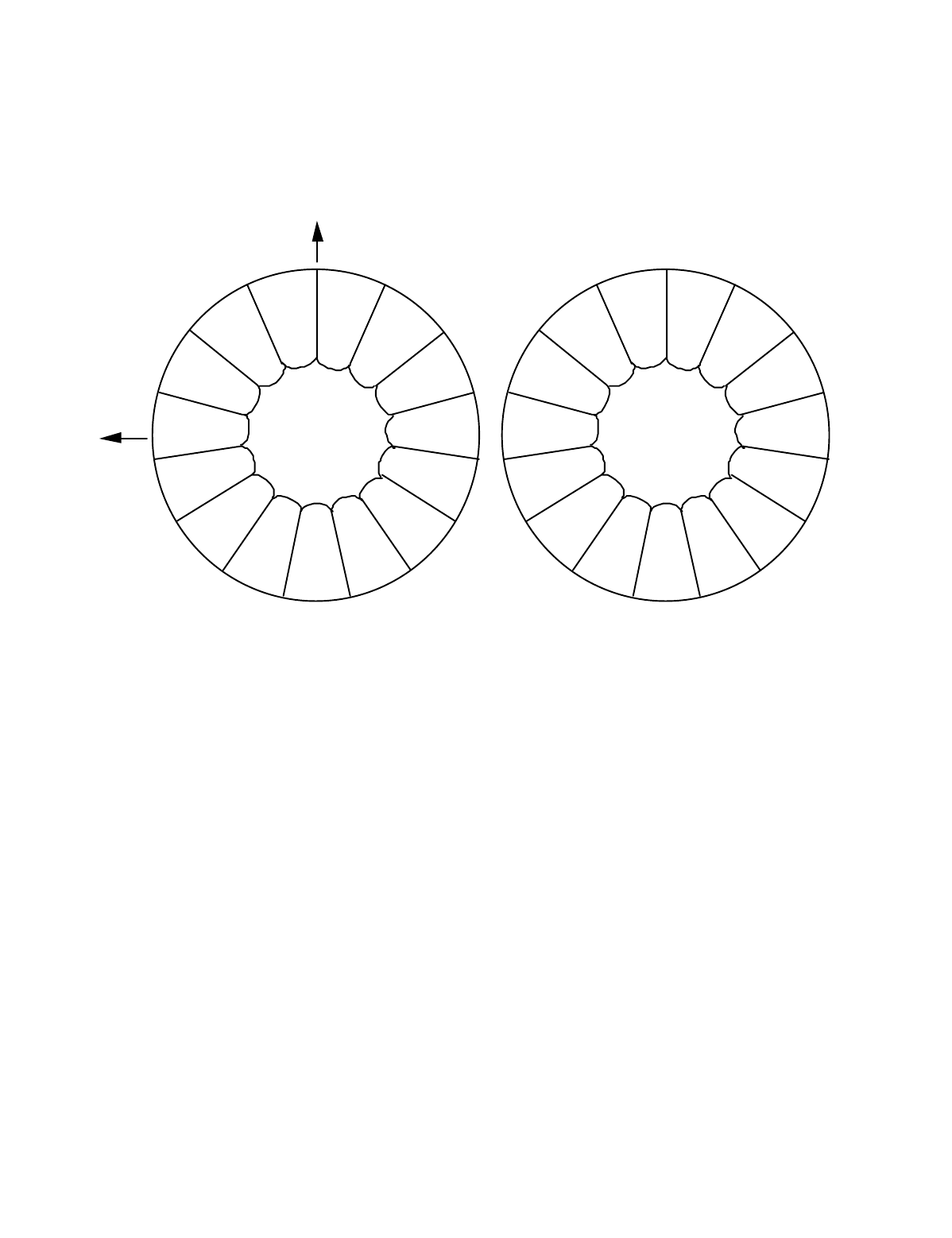
Description of the Globalstar System GS-TR-94-0001
Revision E
3-3
L-Band Pattern: The L-Band pattern consists of 16 beams. Beam 1 is in the center. The1
remaining 15 beams are arranged in an annular ring around the center beam as shown in Figure2
3-3.3
891011
12
13
14
15
16
1
2
3
4
5
6
7
+Xsc
+Ysc
Y5
Y1
X4
Y2
X1
Y3
X2Y4
X3
X5
X8
Y6
X7 Y8
X6
Y7
File: L-Beams
Channel Assignments Beam Assignments
View from Satellite
X= LHCP
Y=RHCP
Looking at Earth Nadir
4
Figure 3-3 L- Band Beams
5
This configuration provides better coverage on the earth to reduce the power requirements on the6
L-Band transmitters in the User Terminals.7
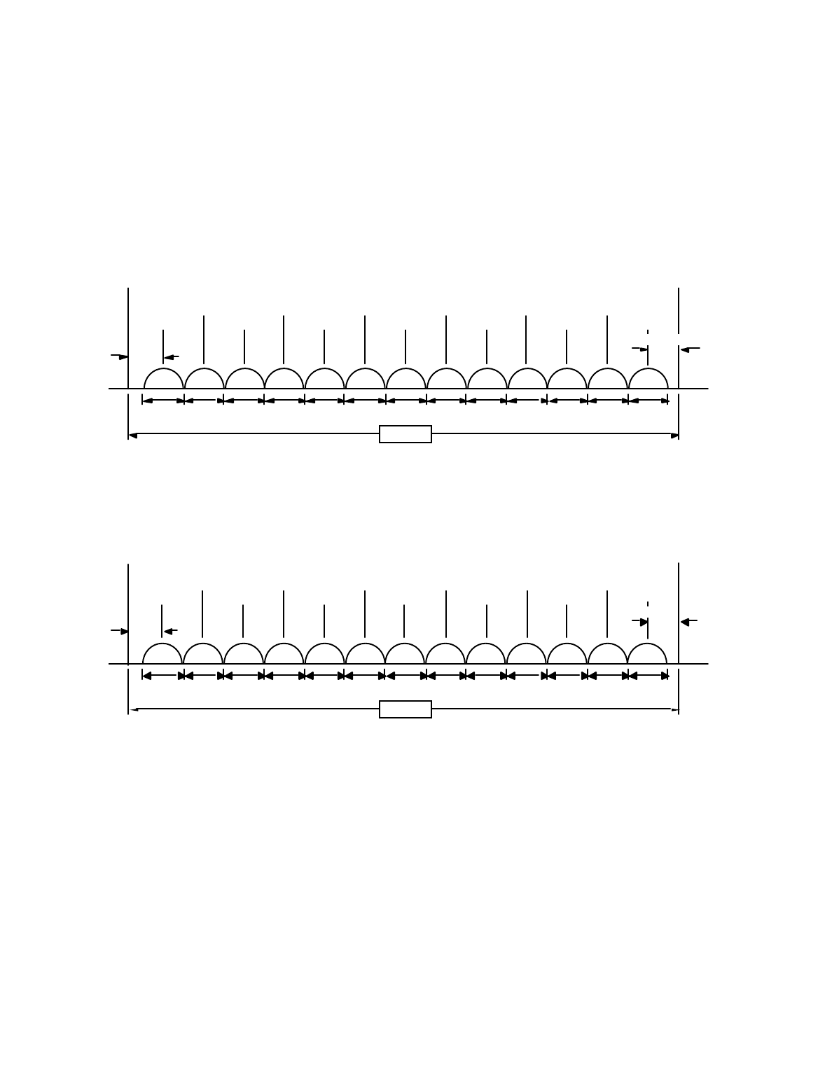
Description of the Globalstar System GS-TR-94-0001
Revision E
3-4
Efficient Spectrum Utilization - As shown in Figure 3-4 and Figure 3-5, only 16.5 MHz of L-1
Band and S-Band spectrum are used. The same set of frequencies are reused in each of the 162
beams. Note that C-Band frequencies are assigned to beams to minimize interference. The3
Globalstar approach is very efficient in its use of the valuable L-Band and S-Band spectrum. L-4
Band is used to communicate from the User Terminal to the satellite and S-Band is used to5
communicate from the Satellite to the User Terminal. Within each of the beams, there are 136
FDM channels.7
1.23 MH z 1.23 MHz 1.23 MHz 1.23 MHz 1. 23 M H z 1.23 MH z 1.23 MH z
1626.5 MHz
162 5.490 MH z
1610.0 MHz
730 kHz
1624.260 MHz
162 3. 030 MH z
1621.800 MHz
1 620 .5 70 MHz
1619.340 MHz
1 618.110 MHz
1616.880 MHz
1 615 .6 50 MHz
1614.420 MHz
1613.190 MHz
161 1.960 MH z
16 10 .7 30 MHz
16.5 MHz
File: L-Band
1010 kHz
12345678910111213
8
Figure 3-4 L - Band Channel
9
Frequencies
10
2500.0 MHz
24 99. 15 0 MHz
2 483 .5 M H z
249 7. 920 MH z
2 496 .6 90 MHz
249 5.460 MH z
249 4. 230 M H z
2 493 .0 00 MHz
2491.770 MHz
2 490.5 40 MHz
248 9. 310 MH z
2 488 .0 80 MHz
2486.85 0 MHz
2 485.6 20 MHz
24 84. 39 0 MHz
1.23 MH z 1.23 MHz 1.23 MHz 1.23 MHz 1. 23 M H z 1.23 MH z 1.23 MH z
89 0 kHz
16.5 MHz
File:S-Band
850 kH z
12345678910111213
11
Figure 3-5 S - Band Channel Frequencies
12
Spectrum Sharing - Within a channel, spread spectrum is used to convey the voice or data13
intelligence. Multiple voice or data circuits may be carried within a single 1.23 MHz FDM14
channel. The circuit data is separated by unique PN spreading sequences. This allows the same15
spectrum to be shared by other CDMA users.16

Description of the Globalstar System GS-TR-94-0001
Revision E
3-5
Satellite Frequency Plan: Table 3-1 illustrates how the C-Band up link signals are converted1
to S-Band down link signals and indicates how the signals are connected to down link beams.2
The table shows the assigned C-Band Frequencies.3
Table 3-1 Satellite C-Band to S-Band
4
C-Band Frequencies S-Band LHCP S-Band RHCP
RF Freq.(MHz) L.O. Freq (MHz) Chan Beam Chan Beam
5105.21 7596.96 X1 12 Y1 9
5124.59 7616.34 X2 14 Y2 11
5143.97 7635.72 X3 16 Y3 13
5163.35 7655.10 X4 10 Y4 15
5182.73 7674.48 X5 1 Y5 8
5202.11 7693.86 X6 6 Y6 3
5221.49 7713.24 X7 4 Y7 7
5240.87 7732.62 X8 2 Y8 5
5091.50 CMD
5
Table 3-2 illustrates the how the Return link is processed in the Satellite. The table shows the6
assigned C-Band Frequencies.7
Table 3-2 Satellite L-Band to C-Band
8
L-Band to C-Band L-Band LHCP L-Band RHCP
RF Freq(MHz) L.O. Freq (MHz) Chan Beam Chan Beam
6908.99 5290.74 X1 8 Y1 3
6928.37 5310.12 X2 10 Y2 15
6947.75 5329.50 X3 4 Y3 13
6967.13 5348.88 X4 6 Y4 11
6986.51 5368.26 X5 1 Y5 5
7005.89 5387.64 X6 14 Y6 9
7025.27 5407.02 X7 2 Y7 7
7044.65 5426.40 X8 12 Y8 16
6876.0-6877.1 (12 ea.) TLM
9
10

Description of the Globalstar System GS-TR-94-0001
Revision E
3-6
Command and Telemetry Frequencies: The telemetry frequencies are listed in Table 3-31
Table 3-3 Satellite Telemetry & Command Frequencies
2
3
Command
Channel No. of Channel Frequency
Bandwidth Channels Width(s) Center(s)
5091 to 1 240 KHz 5091.5
5092 (*)
Telemetry
Channel No. of Chnl Channel Frequency
Bandwidth Channels No. Width(s) Center(s)
6875.95 to 12 1 100 KHz 6876.0
6877.15 2 6876.1
3 6876.2
4 6876.3
5 6876.4
6 6876.5
7 6876.6
8 6876.7
9 6876.8
10 6876.9
11 6877.0
12 6877.1
4
Doppler: The Frequencies that appear at the Globalstar nodes (Gateway, Satellite, UT) differ5
from the assigned frequencies. Doppler is one of the primary contributors. Doppler can be6
computed and the nodes can compensate for the differences in frequency. Table 3-4 indicates7
the magnitude of the Doppler components.8
Table 3-4 Worst Case Doppler
9
Frequency Doppler Rate
Path Name From To (MHz) (KHz) Hz/sec
Forward Uplink Gateway Satellite 5250 97.2 468.8
Fwd Downlink Satellite UT 2500 46.5 224.3
Return Uplink UT Satellite 1626.5 30.2 146.0
Return Downlink Satellite Gateway 7052.9 131.6 634.9
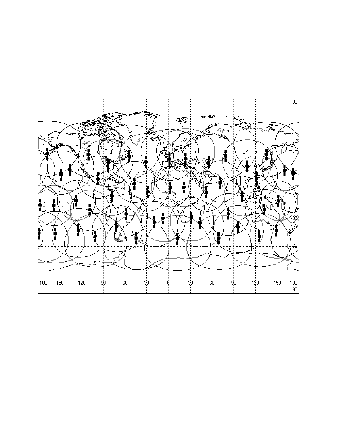
Description of the Globalstar System GS-TR-94-0001
Revision E
3-7
3.3 Earth Surface Coverage
1
The surface of the earth, with the exception of the polar regions, is covered with multiple2
overlapping satellite beams as shown in Figure 3-6.3
4
Figure 3-6 Full Earth Coverage-Except Polar Regions
5
The contours shown indicate that a User Terminal within the contour can communicate with the6
satellite at an elevation angle above 10 degrees.7
Constraining the User Terminals to operate with satellites that have higher elevation angles8
referred to the User Terminal will reduce the overlapping coverage but would provide an9
advantage in that it would reduce the power demands placed on the User Terminal to close the10
link. This would result in longer battery life for the User Terminal.11
Conversely, lowering the angle to the satellite will increase the overlapping coverage. Small12
changes dramatically increase the coverage area. This is particularly apparent in the polar13
regions. If operated at low elevation angles, polar areas that otherwise could not be covered can14
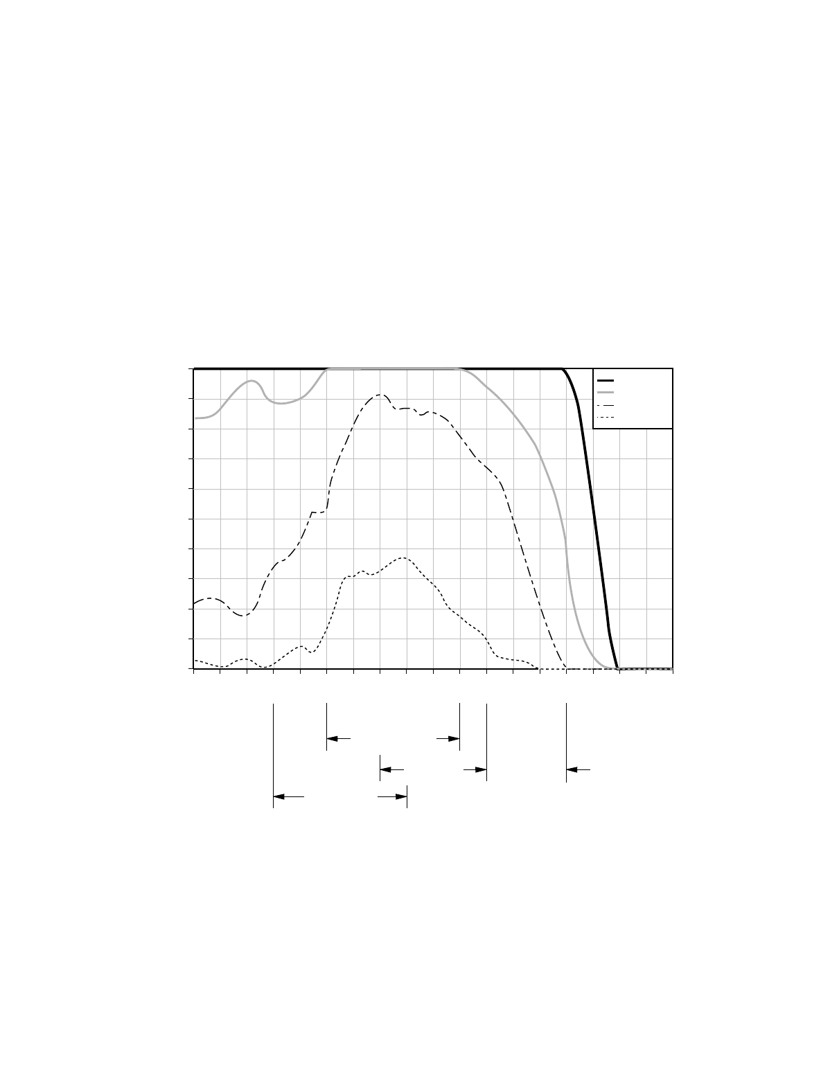
Description of the Globalstar System GS-TR-94-0001
Revision E
3-8
receive service. In polar areas, overlapping coverage would be increased and power demands1
may be increased. In this region the look angle to the satellite is limited. High gain directional2
antennas become practical for fixed and even portable installations. The pay back is that3
Globalstar could now serve areas that otherwise might be unserviceable.4
To a degree, some of these same considerations discussed for polar areas apply to equatorial
5
areas where the overlapping coverage is less than 100%.6
Satellites in View as a Function of Latitude: Figure 3-7 illustrates the multiple satellite7
coverage more clearly.8
100.0
90.0
80.0
70.0
60.0
50.0
40.0
30.0
20.0
10.0
0.0
0 5 10 15 20 25 30 35 40 45 50 55 60 65 70 75 80 85 90
Multiple Satellite Coverage Versus Latitude
(10 degree elevation angle, 48 satellite constellation)
USA (CONUS)
CENTRAL
EUROPE SCANDINAVIA
AUSTRALIA
Latitude
% of Time
1 or more
2 or more
3 or more
4 or more
9408061
9
Figure 3-7 Enhanced Coverage for Temperate Regions
10
Note that the coverage is optimized to provide multiple coverage in the temperate regions. In11
areas within this temperate region, the User Terminal can communicate via multiple satellites.12
This enhances the link availability and allows the User Terminal to operate with nominal link13
margins.14

Description of the Globalstar System GS-TR-94-0001
Revision E
3-9
Orbital Parameters: The orbital parameters for the initial injection orbit and for the final on1
station orbit are shown in Figure 3-8.2
On Station Phasing Orbit
RAAN Spacing for plane
J=1...8 (Degrees) +/- 1.045
Relative Phasing between
adjacent planes (Degrees) +/- 17.5
Parameter Tol (3 )Mean Tol (3 )Mean
Radius (km) +/- 0.17778 +/- 207298
Orbit Period-Nodal +/- 0.13 sec114 min +/-0.4103.35
Inclination (Degrees) +/- 0.0152 +/- 0.652
Eccentricity + 0.0080.000 + 0.010.000
+/- 160Relative Phasing between
satellites in a plane (Degrees)
Fi le: O r bi tp
Rev 11 /0 6/96
3
Figure 3-8 Orbital Parameters for Globalstar Satellites
4
Supplementary Coverage: There are two problem areas in the coverage.
5
1. One is over the equator where the beam is narrow. There has been some study of using some
6
additional satellites to cover the equatorial area. At this point in time, this is not financially
7
justified. If more business is identified as we penetrate Indonesia, the Philippines, India,
8
Central Africa, and Central America enhanced coverage may be examined again.
9
2. The second area that is not covered well is the polar area. Some study of supplementing
10
coverage with Molniya orbit satellites has been performed. This type of orbit “hangs” in the
11
polar areas for a long period and then orbits over the south polar area very rapidly. If
12
coverage of the northern areas becomes economically justified, this may be re-visited.
13
The other thing to be considered in northern areas, such as the islands north of mainland Russia,
14
is the inclination of the satellites. They do not go beyond 52 degrees north. This means a fixed
15
UT antenna can be pointed south only. Gain can be obtained due to the directivity. Fixed User
16
Terminals could operate much further north if they do not require an omni-directional Fixed
17
User Terminal antenna.
18

Description of the Globalstar System GS-TR-94-0001
Revision E
3-10
3.4 Position Determination
1
The location of the User Terminal is determined by Globalstar and used for several purposes.2
Any position location services that may be provided should be considered a by product of the3
Globalstar System. The primary purpose of Globalstar is to provide communications. It should4
not be considered as a competitor or replacement for GPS or GLONASS. Two basic accuracy5
are supported.6
Low Accuracy: The user terminal is located to within 10 km for purposes of National7
Sovereignty, to assign the user to a gateway, and to support registration. This accuracy is8
sufficient for the gateway to determine which satellite/beam should be used for phone9
paging. This avoids having to page on multiple satellites/beams at the cost of capacity.10
High Accuracy: A higher accuracy on the order of 300 meters is feasible in under some11
conditions. This may be attractive as a service. This high accuracy results from the high12
degree of precision with which the position and velocity of the satellite constellation is13
know. Each satellite incorporates a GPS receiver to determine position and rate of14
change of position. When this data is processed with other data at the SOCC the15
precision of the orbit becomes quite good. The CDMA, for its own purposes, needs to16
align chips within 1/8 of a chip. Potential for high positioning accuracy is inherent.17
The User Terminal may determine its position with the assistance of the Gateway or it may18
determine its position autonomously. In all cases, determination of position is based on19
determining the intersection of three or more spheres in 3-dimensional space. The surface of the20
earth can be used as one of the spheres. The Gateway has the processing power to make active21
determination attractive. This must be traded for additional messaging that will be required to22
support active determination of position.23
Active Determination: The Gateway calculates range based on time delay between the24
User Terminal and the Gateway through a satellite. The phone transmission can be an25
access probe or an ongoing call, but it must be synchronized in some fashion to the26
forward link signal. When this accomplished through two satellites with the proper27
geometry, excellent positioning accuracy can be achieved.28
Passive Determination: The User Terminal can determine its location without the29
assistance of the Gateway. In this mode, since time is not known very well this means30
the system has an extra degree of freedom. The phone measures a T between two31
different satellites, and another T using a third satellite. Three 3 satellites are required,32
to solve for the phone's clock offset. An additional form of passive position33
determination incorporates measurements of the satellite velocities relative to the phone,34
instead of or in addition to the satellite ranges to the phone. This is done by measuring35
the received Doppler shift of the satellite signal.36

Description of the Globalstar System GS-TR-94-0001
Revision E
3-11
Any of the techniques must incorporate the following generic considerations.1
Geometric Dilution Of Precision (GDOP): This is a phenomenon that affects all2
forms of position determination. It is due to the orientation of the satellites from the3
phone's perspective. When the geometry is good, precision is good. When poor, the4
accuracy degrades very quickly.5
Time to Position: Time to achieve an accurate position depends on the time. In simple6
forms, the more time the more precise the location.7
Geographical Constraints: Position determination becomes more difficult when the8
User Terminals are on the equator or at high latitudes. In these cases, only one satellite9
may be visible. This means that range must be determined at one point in time and the10
range determined again at another point in time. Under these conditions the geometry is11
less than optimal, resulting in a long time to achieve a valid position determination and12
an inaccurate determination of position.13
Terrain Maps: For the surface of the earth to be used as one of the intersecting spheres,14
a terrain map must be used to determine altitude above the mean surface of the earth.15
The degree of granularity of this map will impact the accuracy that can be achieved and16
will impact the time to achieve a position indication.17
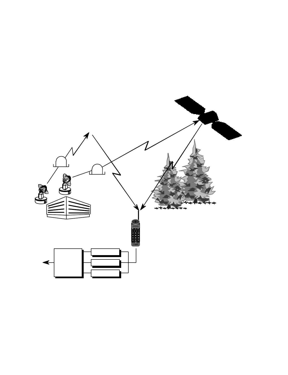
Description of the Globalstar System GS-TR-94-0001
Revision E
3-12
3.5 Channel Characteristics
1
Figure 3-9 illustrates the orientation of a User Terminal in a typical temperate climate scenario2
with multiple satellite coverage.3
Channel 5
COMBINER
RECEIVER 1
RECEIVER 2
RECEIVER 3
Globalstar
Handset
Globalstar Gateway
S1 S1 S2 S2
Globalstar 1 Globalstar 2
Channel 5
Decoder
&
Vocoder
4
Figure 3-9 Channel Characteristics Considerations
5
Line of Sight: For the Globalstar system, many of the obstructions in the direct line of sight do6
not completely block the line of sight, but rather simply attenuate the signal. Given two7
satellites in view at the same time, the probability of signal blockage or shadowing to both8
satellites is significantly less than the probability of blockage to a single satellite.9

Description of the Globalstar System GS-TR-94-0001
Revision E
3-13
Specular Reflection: The specular reflection component is the signal reflected off the surface1
of the earth. The magnitude of the reflected signal can be large if the surface is relatively smooth2
and flat at the point of reflection. The specular component will prove to be an insidious problem3
for the hand held antennas. It can either add to or subtract from the signal received from the4
direct line of sight. This problem can be managed effectively for the mobile and the fixed5
station antennas.6
Diffuse Reflection: The diffuse component is composed of a sum of a large number of7
individual terrain scatter from outside the first Fresnel zone. This diffuse component is8
characterized by phase incoherent multi-path with a uniform phase distribution and a Rayleigh9
amplitude distribution. The signal fading associated with the diffuse component combining with10
the direct component produces the fast-fading characteristics of the propagation channel.11
Building Penetration: Globalstar has limited ability to penetrate buildings. Operation is
12
possible in wood frame buildings or near windows with a wide angle view of the sky. The best13
locations within building results in 6 to 13 dB added insertion loss. There is a high degree of14
sensitivity to antenna location within the building. A change in lateral position of 20 to15
30 centimeters can produce a 30-dB variation in signal power.16
In Pocket: With the antenna extended, operation depends on orientation. Body blockage can17
insert attenuation in excess of 15 dB. If the antenna is stowed, operation is not considered18
feasible.19
Interference: User Terminal receivers may experience interference when operating in close20
proximity to microwave ovens, plywood plants or hospitals. The transmitters are frequency21
coordinated for operation with Radio Astronomy sites, for operation with GPS, and with22
GLONASS. The Gateway site locations are selected to avoid interference with the Microwave23
Landing Systems (MLS) associated with airports.24
Conclusions: Several Conclusions can be drawn for Globalstar operations.25
1. Operation at higher elevation angles is preferred.26
2. Mobile will suffer less from specular. Power control may be less effective at some27
operating speeds.28
3. Fixed terminals will suffer less degradation from all sources.29
4. Forward and Return link behavior are not correlated. Conclusions from one direction30
cannot be used to derive control information for the other direction.31

Description of the Globalstar System GS-TR-94-0001
Revision E
3-14
3.6 Link Analysis
1
The Globalstar system provides spatial diversity to overcome shadowing and blocking. The link2
analysis in this section is based on the current FCC filing which assumes nominal 5.5 meter3
antennas at the Gateways. There are 3 cases that are presented.4
Case 1: This is a detailed link budget. This case considers the forward and return links between5
the Gateway to the User Terminal. The up link from the Gateway to the satellite is C-Band. The6
down link from the satellite to the User Terminal is S-Band. The Return Link is L-Band from7
the User Terminal to the Satellite and C-Band from the satellite to the Gateway. There is no8
shadowing or blocking and diversity is used.9
Case 2: This is an abbreviated link budget that shows only the differences from case 1. One10
path is blocked. Only the C-Band or the S-Band can be blocked; since, the Gateway will be in11
one location.12
Case 3: This is a rare case where both links are shadowed or faded by 10 dB.13
Table 3-5 Forward Link C-Band - Case 1 - Detailed Budget
14
Up Link Gateway to Satellite C-Band
Frequency 5125.0 MHz
Nominal EIRP per user 26.8 dBW
Path loss(40 degree. GW elev.) -172.5 dB
Polarization & Tracking. Loss -1.1 dB
Satellite Antenna gain (incl. line loss) 3.1 dB
Receive power/user at LNA -143.7 dBW
Average User Data Rate 2400.0 b/s
System Noise Temperature 549.5 K
Thermal Noise Density, No -201.2 dBW/Hz
Estimate Interference Density -198.5 dBW/Hz
Up link Eb/(No+Io) 19.1 dB
15

Description of the Globalstar System GS-TR-94-0001
Revision E
3-15
Table 3-6 Forward Link S-Band - Case 1 - Detailed Budget
1
Down Link Satellite to User Terminal
Frequency 2495.0 MHz
Nominal EIRP per user -2.9 dBWi
Satellite Altitude 1414.0 km
Typical Elevation Angle 50.0 degrees
Range 1740.5 km
Free Space Loss -165.2 dB
Polarization & Tracking. Loss -1.0 dB
Shadowing Loss 0.0 dB
Receive Signal Strength /user/sat. -169.1 dBWi
User Antenna Gain(incl. line loss) 2.6 dBi
User Signal at antenna output -166.5 dBW
System Noise Temperature 293.7 K
Thermal Noise Density, No -203.9 dBW/Hz
Average Data Rate, Rb 2400.0 b/s
Down link Eb/No 3.6 dB
Interference per Channel -148.6 dBW
Spreading Bandwidth 1.23 MHz
-10*log(spreading BW) -60.9 dB/Hz
Interference Density, Io -209.5 dBW/Hz
Down link Eb/(No+Io) 2.6 dB
Coherent combining gain 2.5 dB
Overall Eb/(No+Io) (up&dn) 5.0 dB
Operating Eb/No 5.0 dB
2
3

Description of the Globalstar System GS-TR-94-0001
Revision E
3-16
Table 3-7 Forward Link - Case 2 - Link Blockage
1
C-Band Up Link and S-Band Down Link
Up link
EIRP per user 28.8 dBW
Up link Eb/(No+Io) 21.1 dB
Down link
EIRP per user -0.4 dBW
Down link Eb/(No+Io) 5.1 dB
Coherent combining gain 0.0 dB
Overall Eb/(No+Io) 5.0 dB
2
Table 3-8 Forward Link - Case 3 - Rare Two Link Fade
3
C-Band Up Link and S-Band Down Link
Up link
EIRP per user 36.3 dBW
Up link Eb/(No+Io) 28.6 dB
Down link
EIRP per user 7.1 dBW
Shadowing loss -10.0 dB
Down link Eb/(No+Io) 2.6 dB
Coherent combining gain 2.5 dB
Overall Eb/(No+Io) 5.0 dB
4

Description of the Globalstar System GS-TR-94-0001
Revision E
3-17
Table 3-9 Return Link L-Band - Case 1 - Detailed Budget
1
Up Link User Terminal to Satellite
Frequency 1615.0 MHz
Nominal EIRP per user -11.2 dBWi
Satellite Altitude 1414.0 km
Typical elevation angle 70.0 degrees
Range 1487.1 km
Free Space Loss -160.1 dB
Polarization & Tracking. Loss -1.0 dB
Shadowing loss 0.0 dB
S/C Receive Signal Strength -172.3 dBWi
S/C Antenna Gain (incl. line loss) 11.5 dBi
User Signal at antenna output -160.8 dBW
System Noise Temperature 500.0 K
Thermal Noise Density, No -201.6 dBW/Hz
Average data rate, Rb 2400.0 b/s
Up link Eb/No 7.0 dB
Interference per channel -142.2 dBW
Spreading bandwidth 1.23 MHz
Interference Density -203.1 dBW/Hz
Up link Eb/(No+Io) 4.7 dB
2

Description of the Globalstar System GS-TR-94-0001
Revision E
3-18
Table 3-10 Return Link C-Band - Case 1 - Detailed Budget
1
Down Link Satellite to Gateway
Frequency 6975.0 MHz
Nominal EIRP per user -27.7 dBW
Path loss (40 degree GW elev.) -175.2 dB
Polarization & Tracking. loss -1.1 dB
GW antenna gain 49.4 dB
Receive power/user -154.5 dBW
System noise temp. 127.7 K
Thermal noise density, No -207.5 dBW/Hz
Interference Density, Io -212.3 dBW/Hz
Down link Eb/(No+Io) 18.0 dB
Combining gain 1.8 dB
Overall Eb/(No+Io)(up&dn) 6.3 dB
Operating Eb/No 6.3 dB
2
Table 3-11 Return Link - Case 2 - Link Blockage
3
L-Band Up Link and C- Band Down Link
Up link
EIRP per user -9.4 dBW
Up link Eb/(No+Io) 6.5 dB
Down link
EIRP per user -25.9 dBW
Down link Eb/(No+Io) 19.8 dB
Combining gain 0.0 dB
Overall Eb/(No+Io)(up&dn) 6.3 dB

Description of the Globalstar System GS-TR-94-0001
Revision E
3-19
1
Table 3-12 Return Link - Case 3 - Rare Two Link Fade
2
L- Band Up Link and C- Band Down Link
Up link
EIRP per user -1.2 dBW
Shadowing loss -10.0 dB
Up link Eb/(No+Io) 4.7 dB
Down link
EIRP per user -27.7 dBW
Down link Eb/(No+Io) 18.0 dBW
Combining gain 1.8 dB
Overall Eb/(No+Io)(up&dn) 6.3 dB
3
Forward Link: The link from the Gateway to the User Terminal reduces self interference
4
within an FDM channel by coherent transmissions and by using CDMA Walsh codes which are
5
orthogonal.
6
Return Link: The Return link uses paths through multiple satellites to combat the effects of
7
shadowing, blockage and multi-path.
8

Description of the Globalstar System GS-TR-94-0001
Revision E
3-20
This page intentionally left blank.1
2

Description of the Globalstar System GS-TR-94-0001
Revision E
4-1
4. CODE DIVISION MULTIPLE ACCESS (CDMA)1
4.1 Introduction2
The Globalstar Air Interface uses a modified form of IS-95 to support Code Division Multiple Access.3
CDMA was selected for Globalstar because it represents a proven technology that can provide a4
bandwidth efficient modulation scheme for satellite communications. It is relatively interference tolerant,5
both from the standpoint of generation of interference to other services and tolerating outside6
interference. As a bonus, there is a level of security inherent in the modulation scheme. It is difficult to7
listen into conversations or to pirate services from the system. CDMA is able to provide good voice8
quality while operating at relatively low RF power levels. The Globalstar CDMA is based on the9
existing QUALCOMM CDMA product line used for terrestrial cellular communications.10
Path Diversity combats fades and blockage - Probably one of the most important aspects of11
CDMA is associated with the way Globalstar uses CDMA. Diversity combining is used to provide12
continuous communications even under conditions where a path to one satellite is totally blocked. The13
Globalstar system can operate with relatively low link margins and still provide a high link availability.14
CDMA supports spectrum sharing - There are other useful and interesting aspects of CDMA. In15
CDMA two or more systems can occupy the same frequency-power space. Separation of the16
intelligence is accomplished by demodulating the PN spreading sequence. This supports band sharing17
by more than one system.18
Soft Capacity Limit: There is another useful aspect of CDMA. Since CDMA is basically a system19
whose capacity is limited by self generated interference, the limit is a soft limit. Unlike bandwidth limited20
systems like Time Division Multiple Access (TDMA) or Frequency Division Multiple Access (FDMA),21
CDMA allows the predicted capacity limit to be exceeded with soft degradation occurring.22
Description of the Globalstar System GS-TR-94-0001
Revision E
4-2
4.2 Diversity Combining1
Diversity combining is used to mitigate the effects of link phenomena. In a simple form, diversity2
combining uses the signal with the best signal to noise ratio. Rake receivers are used to receive and3
combine the signals from multiple sources. As an example, the User Terminal will provide diversity4
combining for the forward link signals received through up to two different links simultaneously.5
Diversity increases Availability - The performance in the diversity mode will always exceed the6
performance that would be achieved with communications via a single string link. Diversity combining is7
continuous. There is no break in service if one or more of the diversity links is lost.8
Multiple Satellite - Forward Link: In the forward direction, the use of diversity brings substantial9
gain if one of the satellites is obstructed and is break even for unobstructed operation without multi-path.10
With multi-path fading (typically with high values of Ricean k) the diversity also provides benefit.11
Multiple Satellite - Return Link: In the reverse direction, there is a clear advantage because gain12
results even with no obstruction. Because this is non coherent diversity combining, the gain is not quite13
as much as with coherent operation.14
Multiple Beam - Forward Link: There is no diversity advantage for using multiple beams. All beams15
come from precisely the same point in the sky and are at the same sub-channel frequency. Whatever16
shadowing or multi-path occurs for one beam occurs for the other.17
Multiple Beam - Return Link: On the Return Channel the signals the gateway sees through the18
different beams are, of course, the same; they fade in exactly the same way. But the noise backgrounds19
in which they are received are essentially independent. There is some advantage to using diversity.20
4.3 Fade Mitigation21
The Gateway will support power control to address slow fades and interleaving to address medium to22
fast fades. Power control is implemented on both the forward and return links.23
Power Control: To support forward link power control, the user terminal reports pilot quality statistics24
to the gateway. For return link power control, the Gateway measures frame error rate. The response25
time of the power control is adjusted to accommodate the satellite round trip time delays. Average26
round trip delay is on the order of 30 ms.27
Forward Link: Forward link power control is closed loop under control of the Gateway. The28
dynamic range of the forward link power control is at least 20 dB.29
Return Link: The return link is operated open loop when a fade is first sensed, then closed30
loop under control of the Gateway. The dynamic range of the return link power control is a31
Description of a Globalstar Gateway GS-TR-94-0001
Revision E
4-3
maximum of 20 dB with a 0.5 dB step size. The User Terminal will limit the integrated1
transmitted power to conform with regulatory requirements.2
Interleaver: The Interleavers will operate over a 20 ms vocoder packet frame which will effectively3
address medium and fast fades.4
4.4 Acquisition5
Search to Acquire: When a Globalstar phone hunts for a pilot channel it must search through a multi-6
dimensional space. Three of the more obvious dimensions are illustrated in Figure 4-1.7
PN Code
Frequency Doppler
PN Timing
8
Figure 4-1 Acquisition Search Space9
The goal is to reduce the search volumes by all means practical. Given that the search volume is10
decreased; then parallel processing can be used to speed the search process without compromise to the11
probability of a correct acquisition.12
Description of the Globalstar System GS-TR-94-0001
Revision E
4-4
Latitude Dependence: The acquisition time is also a function of other variables such as latitude as1
shown in Figure 4-2.2
0
1
2
3
4
5
6
0 2 0 4 0 6 0
Latitu d e (deg)
Time (secs)
PPS Me an
PPS 95%
3
Figure 4-2 Acquisition Time as a function of Latitude4
The Search is latitude dependent due to the orbital geometry. Less satellites are visible at high latitudes.5
Several approaches are used to attain this apparent rapid response. Parallel searching speeds the6
search process materially. The Ground Operations Control Center (GOCC) is also involved in speed7
up of the search process. The search times shown in Figure 4-2 apply if the pilot frequency is known.8
The GOCC can help by assigning the pilot frequencies near the center of the band in a given9
geographical area. This basically collapses the search frequency dimension shown in Figure 4-1 to the10
uncertainty due to Doppler.11
Summary: This means that if the User Terminal stays in its home gateway area the acquisition process12
can be very quick. If the pilot frequency is unknown due either to poor assignment by the GOCC or13
due to the User Terminal roaming to another gateway area, the search time can extend. Basically the14
maximum search time is the number of pilots that must be searched times the time to acquire as shown in15
Figure 4-2. The mean time to acquire is roughly half of the maximum time to acquire.16
Description of a Globalstar Gateway GS-TR-94-0001
Revision E
4-5
4.5 Forward CDMA Channel1
An example assignment of the code channels transmitted by a gateway is shown in Figure 4-3. Out of2
the 128 code channels available for use, the example depicts the Pilot Channel (always required), one3
Sync Channel, seven Paging Channels (the maximum number allowed), and 119 Traffic Channels of4
Rate Set 1. Another possible configuration could replace all the Paging Channels and the Sync Channel5
one for one with Traffic Channels of Rate Set 1, for a maximum of one Pilot Channel, zero Paging6
Channels, zero Sync Channels, and 127 Traffic Channels of Rate Set 1.7
Pilot
Chan
Paging
Ch 1
Paging
Ch 7
Sync
Chan
Traffic
Ch 1
• • •
Up
to
FORWARD CDMA CHANNEL
(1.23 MHz channel transmitted
by gateway)
Traffic
Ch 119
Traffic
Ch N
• • •
Up
to
Power Control
Sub-Channel
Traffic Data
•••••••••••••••
8
Figure 4-3 Forward CDMA Channel Transmitted by a Gateway9
The forward CDMA channel consists of the Pilot Channel, one Sync Channel, up to seven Paging10
Channels, and a number of Forward Traffic Channels. Multiple Forward Channels are used in a11
Gateway by placing each Forward Channel on a different frequency.12
Description of the Globalstar System GS-TR-94-0001
Revision E
4-6
The forward link Pilot, Sync and Paging Channel is generated as shown in Figure 4-4.1
Convolutional
Encoder
r=1/2 K=9
Paging
Channel
Bits
Code
Symbol
Walsh Function p
PN Chip,
1.2288 Mcps
Decimator
Long Code
Generator
Long Code
Mask for
Paging
Channel k
4.8 kbps
2.4 kbps
Sync
Channel
Bits
Pilot
Channel
(All 0's)
W
a
l
s
h
F
u
n
c
t
i
o
n
0 or 1
PN Chip,
1.2288 Mcps
Block
Interleaver
Modulation
Symbol
9.6 ksps
4.8 ksps
9.6 ksps
Convolutional
Encoder
r=1/2 K=9
Code
Symbol
Symbol
Repetition
Modulation
Symbol
Walsh Function
32 or 33
PN Chip,
1.2288 Mcps
1.2 kbps
Block
Interleaver
Modulation
Symbol
4.8 ksps2.4 ksps 4.8 ksps
9.6 ksps
1.2288 Mcps
A
A
A
Symbol
Repetition
Modulation
Symbol
9.6 ksps
2
Figure 4-4 Forward Link Pilot, Sync and Paging Channel3
The forward link is modulated as follows.4
Pilot Channel: The Pilot Channel is transmitted continuously by the Gateway and is utilized by the5
User Terminals operating within the coverage area of the Gateway to acquire timing on the forward6
channel, to provide a phase reference for coherent demodulation and to provide signal strength7
comparisons that govern when to do hand offs. The Pilot channel will generate an all zeros Walsh8
Code. This is combined with the short code used to separate signals from different Gateways and9
different satellites. The pilot channel is modulo 2 added to the 1.2288 Mc/s short code and is then10
QPSK spread across the 1.23 MHz CDMA bandwidth. The User Terminal monitors the pilot channel11
and assesses its signal strength at all times except when it is operating in the slotted mode.12
Sync channel: The Sync Channel is an encoded, interleaved, spread and modulated spread spectrum13
signal that is used by the User Terminals operating within the gateway coverage area to acquire initial14
time synchronization. The Sync channel will generate a 1200 b/s data stream that includes (1) time, (2)15
transmitting Gateway identification, (3) assigned paging channel. This is convolutionally encoded and16
Block Interleaved to combat fast fades. The resulting 4800 symbols per second data stream is modulo17
two added to the sync Walsh code at 1.2288 Mc/s and the short code. It is then QPSK spread across18
the 1.23 MHz CDMA bandwidth.19
Description of a Globalstar Gateway GS-TR-94-0001
Revision E
4-7
Paging Channel: The Paging Channel is used for transmission of control information and pages from a1
gateway to a user terminal. The paging channel is convolutionally encoded at Rate = 1/2, Constraint2
length K = 9 and block interleaved. The resulting symbol rate is combined with the long code. The3
paging channel and the long code are modulo two added and provided to the symbol cover where the4
resulting signal is modulo two added to the 1.2288 Mc/s Walsh Code and the short code. The results5
are then QPSK spread across the 1.23 MHz CDMA bandwidth.6
Forward Traffic Channel: The Forward Link Traffic Channel - Rate Set 1 is generated as shown in7
Figure 4-5.8
4.8 kbps
2.4 kbps
0 kbps
Convolutional
Encoder
r=1/2 K=9
Forward Traffic
Channel
Information
Bits for User i with
Rate Set 1
(79, 32, or 0
bits/frame)
Code
Symbol
Block
Interleaver
Add 8-bit
Encoder Tail
Add Frame Quality
Indica-tors (8 , 7,
or 0 bits/frame)
3.95 kbps
1.6 kbps
0 kbps
Symbol
Repetition
Modulation
Symbol
Modulation
Symbol
9.6 ksps
0 ksps
Power
Control
Bits
50 bps
MUX
50 Hz
PN Chip,
1.2288 Mcps
9.6 ksps
0 ksps
9.6 ksps
4.8 ksps
0 ksps
Decimator
Long Code
Generator
Long Code
Mask for
U
s
e
r
i
9.6 ksps
1.2288 McpsDecimator
Walsh
Function j
A
Add Reserved
Bit (1, 1, or 0
bits/frame)4.0 kbps
1.65 kbps
0 kbps
4.4 kbps
2.0 kbps
0 kbps
9
Figure 4-5 Forward Link Traffic Channel - Rate Set 110
Description of the Globalstar System GS-TR-94-0001
Revision E
4-8
The Forward Link Traffic Channel - Rate Set 2 is generated as shown in Figure 4-6.1
9.6 kbps
4.8 kbps
2.4 kbps
0 kbps
Convolutional
Encoder
r=1/2 K=9
Forward Traffic
Channel Information
Bits for User m with
Rate Set 2
(171, 79, 32, or 0
bits/frame)
Code
Symbol
Block
Interleaver
Add 8-bit
Encoder Tail
Add Frame Quality
Indicators (12, 8 , 7,
or 0 bits/frame)
8.55 kbps
3.95 kbps
1.6 kbps
0 kbps
Symbol
Repetition
Modulation
Symbol
Modulation
Symbol
19.2 ksps
0 ksps
Power
Control
Bits
50 bps
MUX
50 Hz
PN Chip,
1.2288 Mcps
19.2 ksps
0 ksps
19.2 ksps
9.6 ksps
4.8 ksps
0 ksps
Decimator
Long Code
Generator
Long Code
Mask for
User m
19.2 ksps
1.2288 McpsDecimator
Walsh
Function n
A
Add Reserved
Bit (1, 1, 1, or 0
bits/frame)8.6 kbps
4.0 kbps
1.65 kbps
0 kbps
9.2 kbps
4.4 kbps
2.0 kbps
0 kbps
2
Figure 4-6 Forward Link Traffic Channel - Rate Set 23
The Vocoder encodes the voice into a PCM data stream. The data stream is the processed as shown4
in Figure 4-5. The resulting data stream is then power controlled and modulo two added to the 1.22885
Mc/s Walsh code and the short code. The results is then QPSK Spread across the 1.23 MHz CDMA6
communication channel bandwidth. The Globalstar Air Interface will support two different rate sets7
from the Gateway. Within a rate set, the Globalstar Air Interface (GAI) will support variable data rate8
operation. When the high rate shown in Figure 4-5 is used, two Walsh codes are required.9
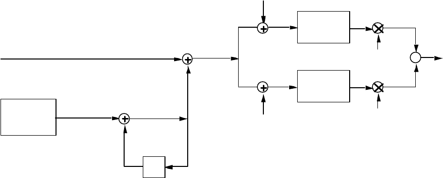
Description of a Globalstar Gateway GS-TR-94-0001
Revision E
4-9
Modulation and Spreading: Modulation and spreading is applied as shown in Figure 4-7.1
A
Q(t)
I(t)Baseband
Filter
Baseband
Filter
I-Channel Inner PN Sequence
1.2288 Mcps
Q-Channel Inner PN Sequence
1.2288 Mcps
I
Q
cos
(2šfct)
sin
(2šfct)
Σs(t)
Outer PN
Sequence
Generator
D
Outer PN Chip
1.2 kcps
1 Outer PN Chip Delay
= 833.333 µs
2
Figure 4-7 Forward Link Modulation and Spreading3
The spreading sequence structure for a given Globalstar CDMA channel is comprised of an inner PN4
sequence pair and a single outer PN sequence. The inner PN sequence has a chip rate of 1.2288 Mcps5
and a length of 1024, while the outer PN sequence has an outer chip rate of 1200 outer chips per6
second and a length of 288; the outer PN sequence modulates the inner PN sequence to produce the7
actual spreading sequence, lasting exactly 240 msec. Exactly one inner PN period is contained within a8
single outer PN chip. The spreading and modulation process applies to all forward link channels.9
Path Identification: It is necessary to know the path that a signal has taken in order to facilitate10
gateway sharing of a forward CDMA channel and to support diversity combining. Path information is11
derived from the pilot signal.12
Gateway: Two gateways can share a forward CDMA channel. Pilot channel 0 is assigned to13
the first gateway can be allocated more power and serve as a beacon pilot within the beam to14
increase acquisition speed of the User Terminals in the beam.15
Orbital Plane: The inner PN sequence is used to identify the orbital plane. The length of the16
sequence is 2 10 chips at a chip rate of 1.2288 mcps. there are 24 repetitions every 20 ms.17
Satellite: Each satellite is identified by a pilot PN sequence.18
Beam: Each Satellite Beam has a unique outer PN sequence offset.19

Description of the Globalstar System GS-TR-94-0001
Revision E
4-10
Beam Juxtaposition: Each Adjacent beam within a satellite is identified by a unique inner PN1
sequence offset. Inner PN offsets are reused among non adjacent beams of a satellite.2
Sharing of Forward CDMA Channel: It is also possible for two gateways to share a single3
subbeam. This mode is used when a gateway’s traffic needs only a fraction of a subbeam and each4
gateway must supply a separate pilot. In particular, this mode is useful when a satellite beam is moving5
from gateway service area A to gateway service area B. Gateways A and B can then share a subbeam6
as the traffic from A is ramping down and the traffic from B is ramping up. When sharing the first7
gateway will use all even-numbered code channels, and the second gateway will use all odd-numbered8
code channels.9
The Pilot Channel of the first gateway is transmitted on code channel 0. The Sync Channel associated10
with this Pilot Channel, if it exists, is transmitted on code channel 32. The Primary Paging Channel11
(Paging Channel number 1) of the first gateway, if it exists, is transmitted on code channel 64. Paging12
Channel numbers 2, 3, 4, 5, 6, and 7, if they exist, are transmitted on code channels 2, 66, 4, 68, 6, and13
70, respectively.14
The Pilot Channel of the second gateway is transmitted on code channel 1. The Sync Channel15
associated with this Pilot Channel, if it exists, is transmitted on code channel 33. The Primary Paging16
Channel (Paging Channel number 1) of the second gateway, if it exists, is transmitted on code channel17
65. Paging Channel numbers 2, 3, 4, 5, 6, and 7, if they exist, are transmitted on code channels 3, 67,18
5, 69, 7, and 71, respectively.19
4.6 Return Link CDMA Channel20
The Reverse CDMA Channel is composed of Access Channels and Reverse Traffic Channels as shown21
in Figure 4-8.22
Access
Ch
Traffic
Ch 1
Traffic
Ch m
REVERSE CDMA CHANNEL
(1.23 MHz channel received
by gateway)
••••••••••••••••••••••••••••••••
23
Figure 4-8. Reverse CDMA Channels Received at a Gateway24
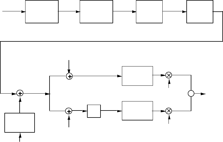
Description of a Globalstar Gateway GS-TR-94-0001
Revision E
4-11
Figure 4-8 shows an example of all of the signals received by a gateway on the Reverse CDMA1
Channel. These channels share the same CDMA frequency assignment using direct-sequence CDMA.2
Each Traffic Channel is identified by a distinct user long code sequence. Each Access Channel is3
identified by its quadrature spreading codes and the gateway identification in the long code mask.4
Multiple Reverse CDMA Channels on different frequencies may be used by a gateway.5
The Reverse CDMA Channel has the overall structure shown in Figure 4-9 and Figure 4-10. Data6
transmitted on the Reverse CDMA Channel is grouped into 20 ms frames. All data transmitted on the7
Reverse CDMA Channel is convolutionally encoded, block interleaved, modulated by the 64-ary8
orthogonal modulation, and direct-sequence spread prior to transmission.9
Access Channel: The Access Channel is used by the User Terminal for communicating to the10
Gateway. It is used for short signaling message exchanges such as call origination, response to pages,11
and registrations. The Access channel is a slotted random access channel. Each Access Channel, as12
shown in Figure 4-9, is identified by a distinct Access Channel long code sequence.13
9.6 ksps
Access Channel
Information
Bits
(88 bits/frame)
Code
Symbol
64-ary
Orthogonal
Modulator
1.6 ksps (102.4 kcps)
Modulation
Symbol
(Walsh chip)
Add 8 bit
Encoder
Tail 4.8 kbps
4.4 kbps
1/2 PN chip
Delay = 406.9 ns
DQ(t)
I(t)
Baseband
Filter
Baseband
Filter
I-channel Sequence
1.2288 Mcps
Q-channel Sequence
1.2288 Mcps
I
Q
1.2288 Mcps
Long
Code
Generator
PN chip
Long Code
Mask
s(t)
sin(2πfct)
cos(2πfct)ΣΣ
Convolutional
Encoder
r=1/2 K=9
Code
Symbol
9.6 ksps
Block
Interleaver
14
Figure 4-9 Return Link Access Channel15
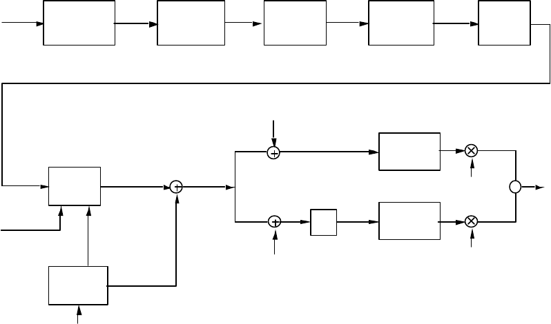
Description of the Globalstar System GS-TR-94-0001
Revision E
4-12
Return Link Traffic Channel: Each Traffic Channel is identified by a distinct user long code1
sequence as shown in Figure 4-10.2
9.6 kbps
4.8 kbps
2.4 kbps
0 kbps
Convolutional
Encoder
r=1/2 K=9
Reverse Traffic
Channel Information
Bits
(171, 79, 32, or 0
bits/frame)
Code
Symbol
Add 8 bit
Encoder Tail
Add Frame Quality
Indicators for
9.6, 4.8 & 2.4 kbps 8.55 kbps
3.95 kbps
1.6 kbps
0 kbps
1/2 PN chip
Delay = 406.9 ns
DQ(t)
I(t)
Baseband
Filter
Baseband
Filter
I-channel Sequence
1.2288 Mcps
Q-channel Sequence
1.2288 Mcps
I
Q1.2288 Mcps
Long
Code
Generator
PN chip
Long Code
Mask
s(t)
sin(2πfct)
cos(2πfct)ΣΣ
19.2 ksps
9.6 ksps
4.8 ksps
0 ksps
64-ary
Orthogonal
Modulator
Modulation
Symbol
(Walsh chip)
3.2 ksps
(204.8 kcps)
1.6 ksps
(102.4 kcps)
0.8 ksps
(51.2 kcps)
0.2 ksps
(12.8 kcps)
Block
Interleaver
Code
Symbol
Add Power Control
Bit for 9.6, 4.8 &
2.4 kbps
Power Control Bit
for 0 kbps Frame
8.6 kbps
4.0 kbps
1.65 kbps
0 kbps
9.2 kbps
4.4 kbps
2.0 kbps
0 kbps
3
Figure 4-10 Return Link Traffic Channel4
The rate 1/2 code used for the Globalstar return link takes advantage of longer coherence times for the5
channel and will perform better in the Additive White Gaussian Noise (AWGN) channel typical of6
Globalstar. The rate 1/3 code, typically used in terrestrial CDMA, performs better in a Rayleigh7
channel because it offers greater diversity. The return link does not use the randomizer used in cellular8
CDMA. It uses a continuous transmission with code symbol repetition to maintain the same rate.9
4.7 CDMA End to End Performance10
There are a number of other CDMA topics that span both the forward and return links.11
Time: All gateway digital transmissions are referenced to a common CDMA system-wide time scale12
that uses the Global Positioning System (GPS) time scale, which is traceable to and synchronous with13
Universal Coordinated Time (UTC). GPS and UTC differ by an integer number of seconds, specifically14
the number of leap second corrections added to UTC since January 6, 1980. The start of CDMA15
System Time is January 6, 1980 00:00:00 UTC, which coincides with the start of GPS time. System16
Time keeps track of leap second corrections to UTC but does not use these corrections for physical17
adjustments to the System Time clocks. When receiving the paging channel, the User Terminal is within18
1.0 microseconds of the earliest arriving signal used for demodulation.19
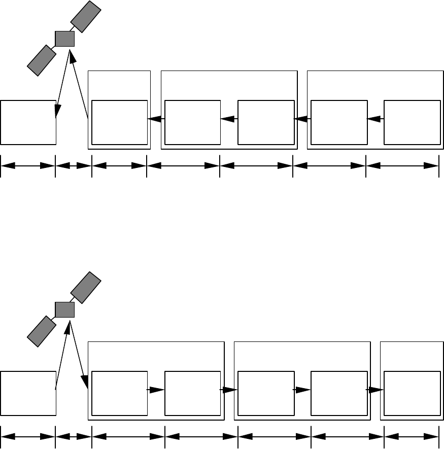
Description of a Globalstar Gateway GS-TR-94-0001
Revision E
4-13
Link Delay: Delay through a link is an important end to end parameter. It becomes particularly1
important in conversations when one party attempts to interrupt the other. The LEO orbit satellites will2
provide a much more benign delay than the more common synchronous orbit satellites. Delay is held to3
150 ms in each direction. There is a design margin, of course. Figure 4-11 summarizes the delay for the4
forward link.5
SBS
Sample &
Vocoder
Encode
MSSL
Queue &
Transmit
Distribute
MSSL
Queue &
Transmit
HDLC
Consolidate
ATM
Modulator
Card
User
Terminal
CISGTS
69 ms0.5 ms1 ms5 ms3.25 ms43.4 ms18 ms
6
Figure 4-11 Forward Link Delay Budget7
Figure 4-12 illustrates the delay budget for the return link.8
SBS
Select &
Vocoder
Decode
MSSL
Queue &
Transmit
Distribute
MSSL
Queue &
Transmit
HDLC
Consolidate
ATM
Demodulator
Card
User
Terminal
CISGTS
3.5 ms0.5 ms1 ms3.5 ms15 ms43.4 ms69.5 ms
9
Figure 4-12 Reverse Link Delay Budget10
Tradeoffs are possible to improve voice quality, improve capacity or other system level parameters at11
the expense of end to end delay.12
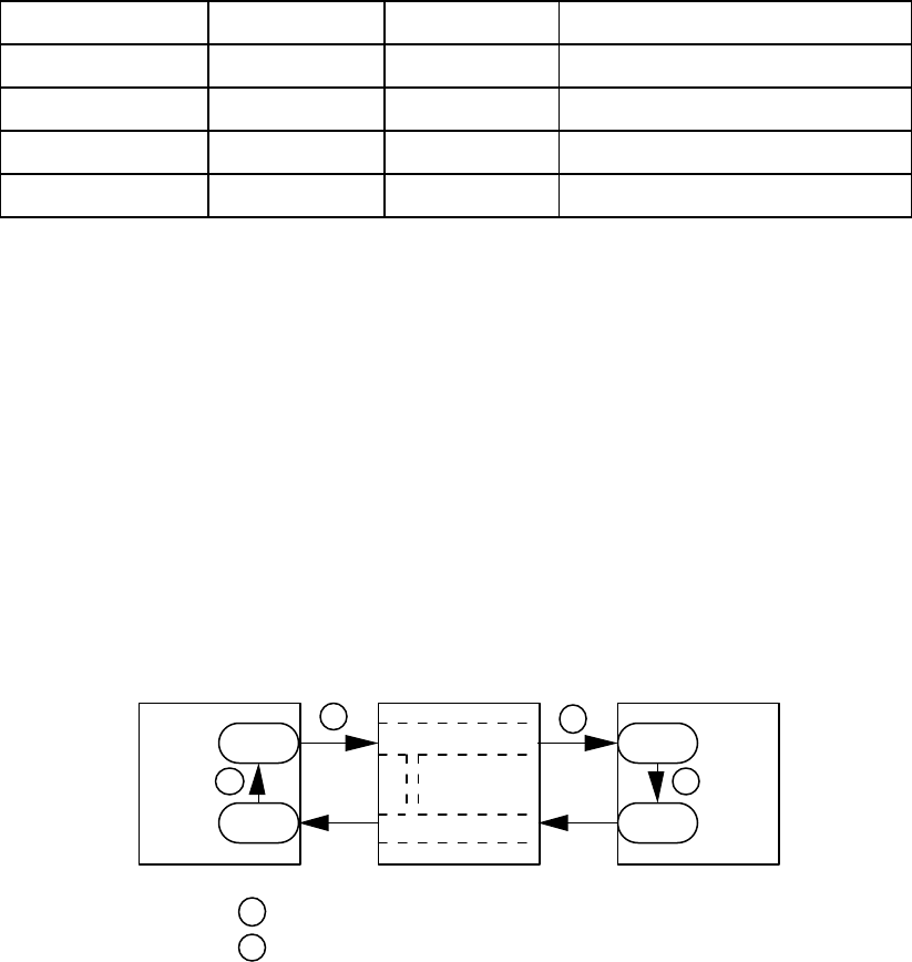
Description of the Globalstar System GS-TR-94-0001
Revision E
4-14
Vocoder: The Globalstar vocoder is uses a Code Excited Linear Prediction (CELP) algorithm with a1
structure similar to that used by the IS-96 coder but with several improvements. The percentage of time2
between rates of 0 b/s and 8,550 can be adjusted. Voice quality can be traded for capacity. Voice3
quality can also be traded for signal delay. The Globalstar design will operate with high voice quality4
when the capacity is not stressed and when the links can be closed. If the links cannot be closed or if5
the capacity is being stressed, voice quality can be sacrificed. Vocoder rates and resulting channel rates6
are shown in Table 4-1.7
Table 4-1 Vocoder and Channel Rates8
Configuration Vocoder Rate Channel Rate Purposes
Rate 1 8,550 9,600 High Quality Option
Rate 1/2 3,950 4,800 Baseline Voiced
Rate 1/4 1,750 2,400 Baseline Unvoiced
Rate 1/8 800 1,200 Baseline Pauses/Background
9
Some improvements are envisioned that may increase capacity. In the forward direction, a zero rate10
can be used. Since this is the coherent direction, the User Terminals can stay locked on by using the11
pilot. This is the direction that constrains capacity. In the return direction, some energy must be12
transmitted to keep the receiver locked since the return direction is not coherent.13
Power Control: The objective of power control is to transmit the minimum power necessary in order14
to achieve a given quality of service. Quality of service could be specified in terms of the Frame Error15
Rate (FER) and the probability of outage. Accurate power control reduces the transmit power needed16
to achieve a given quality of service objective, thereby prolonging battery life of portable phones. In17
addition, it also enhances capacity. Figure 4-13 is a simplified end to end diagram to support the18
description of power control.19
Channel GatewayPhone
tx
txrx
rx
Reverse Link
Forward Link
Correlation
Segment Transmit PathB
Transmit Gain Setting: Power Control AlgorithmA
B
B
AA
20
Figure 4-13 Power Control Simplified Diagram21
Power Control and time to acquire are intimately related as shown in Figure 4-14.22
Description of a Globalstar Gateway GS-TR-94-0001
Revision E
4-15
0
10
20
30
40
50
60
70
80
90
-20 -18 -16 -14 -12 -10
Ec/Io (dB)
95% Time
Mean Time
1
Figure 4-14 Acquisition Time as a function of Eb/No2
Once the target for Eb/No is established, the task of power control is to maintain the desired Eb/No.3
Acquisition time will extend if the Eb/No is not well established correctly or controlled to the desired4
value. In order to achieve the power control there are two loops.5
Inner Loop: The inner loop controls to the target Eb/No on a one bit per frame basis.6
Outer Loop: The outer loop adjusts the target Eb/No based on the measured Frame Error Rate.7
Description of the Globalstar System GS-TR-94-0001
Revision E
4-16
This page intentionally left blank.1
2
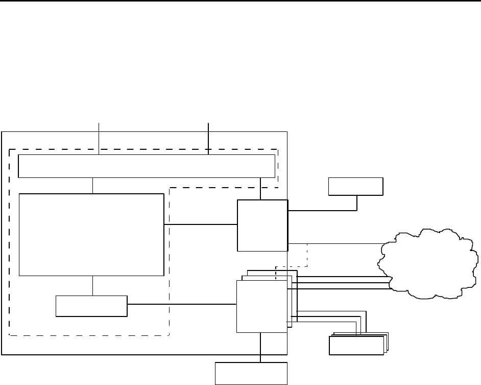
Description of the Globalstar System GS-TR-94-0001
Revision E
5-1
5. TERRESTRIAL INTERFACE1
5.1 Telecommunication Network Interface2
The Gateway Architecture emphasizing the terrestrial interface is shown in Figure 5-1.3
GSM HLR
GSM HLR
CDMA
Subsystem
(GTS/TFU/CIS/
SBS/GC)
IS-41
CCP/VLR
SSA
GSM HLR
IS-41 HLR
GOCC SPCCs
OMC/SPCC
GSM
MSC/VLR
GSM
MSC/VLR
Q Interface
A1 Interface(s)
GSM MAP
IS-41 MAP
T1/E1 - ISUP/MF-R2
T1/E1 - ISUP/MF-R2
GMS
Gateway
GSM
MSC/VLR
BSCI
BSS
PSTN
4
Figure 5-1 Gateway Architecture5
The Gateway can operate in territories with terrestrial systems which are predominately GSM based or6
IS-41 C based.7
GSM: In a GSM environment, the GSM-MSC can either be incorporated in the Gateway or it can be8
external. If external, it can be directly associated with the Gateway or shared with other terrestrial9
cellular systems. A protocol conversion process may be required to support IS-41 roamers whose10
home networks use ANSI SS-7 for MAP signaling rather than ITU SS-7. Protocol conversion may be11
performed by the international SS-7 carrier or by a separate device. GSM roamers whose home12
networks comply with ITU SS-7 do not require protocol conversion support.13
IS-41: In an IS-41 network, a GSM-MSC must be available to provide GSM roaming services. The14
switch can either be in the gateway or can be back hauled to a GSM-MSC in another location.15
Description of the Globalstar System GS-TR-94-0001
Revision E
5-2
Protocol conversion may be required to convert between ITU SS-7 and ANSI SS-7 for mobility1
signaling to support international roamers with different home signaling protocols.2
Flexible Interface: In areas where there is no infrastructure or where there is an infrastructure other3
than GSM or IS-41, the Gateway can interface directly to the PSTN. The Gateway has a built in4
switch than can be adapted to a variety of PSTNs. This, of course, does not address type qualification5
which may or may not be a large problem depending on the specific country and situation involved.6
The entities associated with the terrestrial network of primary interest include:7
GSM MSC/VLR: The GSM Mobile Switching Center (MSC) and Visitor Location Register (VLR)8
provide the call control and mobility management functions for GSM based users in the GW coverage9
area. The GSM MSC terminates one end of the A1 Interface, processing the BSSMAP and DTAP10
messages carried on this interface. The GSM VLR maintains the subscriber records for GSM based11
UTs operating on the GW. In addition, the GSM VLR interfaces to the existing GSM terrestrial cellular12
mobile Home Location Register (HLR) network. The GSM MSC also provides an interface to the13
local PSTN via standard signaling protocols (ISUP, MF-R1, MF-R2, etc.).14
GSM HLR/AuC: The GSM HLRs that are accessible from the GW are new or existing terrestrial15
cellular HLRs in the GSM MAP network. These HLRs contain the home subscriber records for GSM16
based GW UT subscribers.17
IS-41 CCP/VLR/SSA: For IS-41 based users in the GW, the IS-41 based call control and mobility18
management functions are processed by the IS-41 CCP/VLR/SSA entity. The IS-41 VLR maintains19
the subscriber records for IS-41 based UTs operating on the GW. In addition, the VLR interfaces to20
the existing IS-41 terrestrial cellular mobile Home Location Register (HLR) network. The SSA21
interfaces the GW to the local PSTN via standard signaling protocols (ISUP, MF-R1, MF-R2, etc.).22
The GW can also be configured in such a manner where the SSA can directly interface to one or more23
of the GW GSM MSCs if desired.24
IS-41 HLR/AuC: The IS-41 HLRs that are accessible from the GW are existing terrestrial cellular25
HLRs in the IS-41 MAP network. These HLRs contain the home subscriber records for IS-41 based26
GW UT subscribers. The IS 41 C Authentication Center provides authentication for its IS-41 C based27
Globlastar Subscribers.28

Description of the Globalstar System GS-TR-94-0001
Revision E
5-3
Figure 5-2 provides more details on what is inside the Globalstar Gateway.1
2
Figure 5-2 Gateway Connections to the PSTN - Flexible Interface3
Physical Interface: The Gateway will connect to telecommunications networks via standard T1/E1.4
This is accomplished by the Service Switching Adjunct (SSA) shown in the upper right of Figure 5.1-2.5
This is also called Service Switching Point (SSP) in intelligent networks.6
PSTN Interface Protocols: The Gateway provides an Integrated Service Digital Network (ISDN)7
interface and will connect to the PSTN via Primary Rate Interface (PRI).8
SPCC GW Links E1 or T1
BCN MSSL
Ethernet
IFL
PSTN
SSA
Patch Panel
CSUNIS
GWRDB
VLR
Patch Panel
Patch Panel
BSCI GSM
MSC
VLR
T1/E1
Trunks
SBS
CIS
(DISCO)
GTS
RL
TFU
GPS Rcvr
Router
SPCC Router
GDN
FL
7 56
12
11
10
8 4
2
1
9 3
Up Converter
SSPA
RL
LNA
Down
Converter
Antennas
(up to 4)
TCU Panel
TCU
TCU
TCU
TCU
GSS
(Gateway Switching System)
GCS
(Gateway CDMA System)
GMS
(Gateway Management System)
GOCCSOCC
TCU
(Telemetry & Command Unit)
ROPI
GRS
(Gateway RF System)
Digital
Cabinets
(up to 13)
Demod
Cards
FL Cabinet
RHCP
LHCP
RHCP
LHCP
GSM
HLR
IS-41
HLR
E1
Trunks
SS7
SS7
SS7
VME
Backplane
Common
Card
Receive
Cabinets
(up to 13)
Receiver
Cards
Controller
Card
SBS Shelf
1/96 calls
Selector
Cards (12)
Interface
Card
ΣΣ
GCU
T1
FL Shelf
(40)
5/polarize/ant
Upconverter
Cards
Modulator
Cards
GDN Router
14
7
*
2
5
8
0
3
69
#
DGlobalstar
DIGITAL BY
ABC
TFU
Cabinet
(2)
Splitters
TFU
Cabinet
(2)
Splitters
1
4
7
*
2
5
8
0
3
6
9
#
ON OFF
D
Globalstar
DIGITAL BY
VME Cage
CCP
VME Cage
GWC
VME Cage
SS7
Server
CDA
VIP
2
1
3
Trunk Set Combinations
(most likely):
· IS-41 territory:
· GSM territory:
T1
1 2
2 3
OMC
GM
OPI
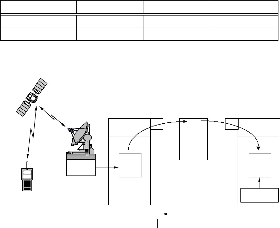
Description of the Globalstar System GS-TR-94-0001
Revision E
5-4
5.2 Registration Process1
Registration is the process by which the User Terminal notifies the Gateway of its location, status,2
identification, User Terminal type, and paging slot being monitored. Under normal circumstances, the3
Globalstar Gateway only contains a Visitor Location Register which is used in conjunction with external4
GSM or IS-41 Home Location Registers. Registration with an external HLR will be supported through5
the Gateway VLR. Registration while roaming involves the exchange of information between system6
types (GSM to IS-41 or visa versa). The messages and procedures for exchange of authentication data7
with the AuC/HLR is currently being reviewed by TIA for inclusion in IS-41D, and is summarized in8
TSB-51, Cellular Radio Telecommunications Inter systems Operation: Authentication, Signaling9
Message Encryption and Voice Privacy.10
There are two registration processes that will be supported.11
User Terminal User ID HLR VLR
IS-95 Modified ESN/MIN IS-41 Globalstar
IS-95 Modified GSM/IMSI GSM Globalstar
IS-41 HLR Registration: Figure 5-3 illustrates the process of registration of an IS-95 User Terminal12
within an IS-41 HLR.13
Home system SPC is
determined from
ESN/MIN
Visitor
Location
Register
(VLR)
SS7
A record is created in the Visitor
Location Register (VLR) and
stored with profile information.
User is deregistered on shutdown
or REGCANC from HLR
Data Message
includes ESN/MIN
or IMEI
1.
2.
6.
The visited Gateway sends
a data message that
includes the phone ESN/MIN
to the HLR across the
signaling network.
3.
IS-41 MAP
messages
(Visiting)
Terminal
User
Home
Location
Register
(HLR)
Home Location Register
SS7
The Customer Profile is
scanned for an ID match
and the present GW
address is updated in
the HLR.
The subscriber profile is
returned to the Gateway.
User is deregistered from
previous VLR (REGCANC)
4.
5.
Gateway
CDMA
Gateway (Visited)
Notes:
ESN = Electronic Serial Number
MIN = Mobile Identification Number
SPC = Switching Point Code
GAI
Globalstar
Air Interface
Authentication
Center (Future)
SS7
Signaling
Network
ANSI
IMEI = International Mobile
Equipment Identifier
IS 41 Authenticates Equipment
ANSIANSI
IS-41 Map
Data
IS-41 Map
Data
File: Reg IS-41
Rev: 10/14/95
14
Figure 5-3 Registration of a U.S. based User with an IS-41 HLR15
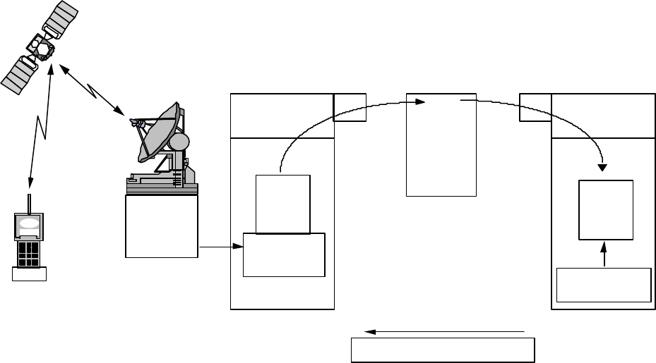
Description of the Globalstar System GS-TR-94-0001
Revision E
5-5
If IMEI are used in the User Terminals, ESN will not be stored. ESN is computed from the IMEI. The1
IMEI also incorporates the type approval code.2
GSM HLR Registration: Here, all of the network components (MSC, HLR, VLR and AuC) should3
be able to communicate as in the normal system. The challenge is reduced to a protocol inter working4
task on the Gateway-VLR and Gateway-MSC interfaces, and transport of GSM authentication data to5
and from the SIM. Figure 5-4 illustrates the registration process.6
Home system SPC
is determined from
the User ID
C 7
Data Messaage
includes User ID
1.
2.
The visited Gateway sends
a data message that
includes the User ID to the
HLR across the signaling
network.
3.
GSM MAP
messages
C 7
Signaling
Network
Visiting
Terminal
GSM User
Home
Location
Register
(HLR)
Home Location Register
C 7
The Customer Profile is
scanned for a User ID
match and the present
location is updated in
the Home Location
Register (HLR).
4.
Gateway
CDMA
Gateway (Visited)
Notes:
SPC = Switching Point Code
ID = Identification
MAP = Mobile Application Protocol
A record is created in the Visitor
Location Register (VLR) and
stored with profile information.
User is deregistered on shutdown
6. The subscriber profile is
returned to the Gateway.
User is deregistered from
previous VLR.
5.
Authentication
Center
Kc Triplet
SIM Card
GAI
Globalstar
Air
Interface ITU
GSM Authenticates Subscriber
GSM - MAP
Data
GSM-A
Visitor
Location
Register
(VLR)
MSC
Mobile
Switching Center
ITU ITU GSM - MAP
Data
File: Reg GSM
Rev: 10/14/95
7
Figure 5-4 Registration of a European User in a GSM HLR8
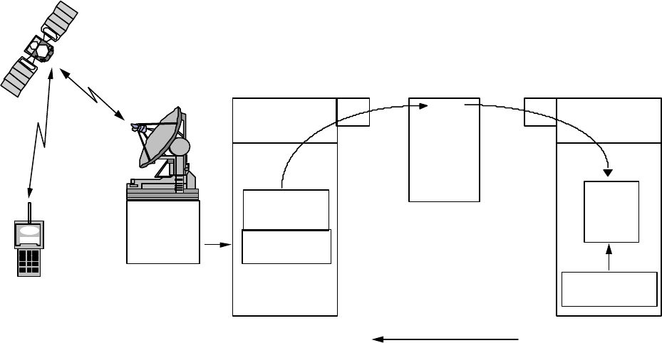
Description of the Globalstar System GS-TR-94-0001
Revision E
5-6
Home system SPC is
determined
C 7
A record is created in the Visitor
Location Register (VLR) and
stored with profile information.
User is deregistered on shutdown
or upon command from the HLR.
2.
6.
The visited Gateway sends
a data message that
includes the phone ID to the
HLR across the signaling
network.
3.
Home Location Register
SS7
The Customer Profile is
scanned for an ID match
and the present GW
address is updated in
the HLR.
The subscriber profile is
returned to the Gateway.
User is deregistered from
previous VLR.
4.
5.
IS-41 MAP
Gateway
CDMA
Gateway (Visited)
Notes:
ESN = Electronic Serial Number
MIN = Mobile Identification Number
SPC = Switching Point Code
ID = Identification (MIN & ESN)
Home
Location
Register
(HLR)
Authentication
Center (Future)
Data Message
includes ESN/MIN
1.
Visiting
Terminal
User
GAI
Globalstar
Air
Interface
or IMEI
IS-41 Call
Control Processor
VLR
IS-41 MAP
ITU SS-7
ITU ANSI
Protocol
Converter
ITU-ANSI
SS-7
Data
File: Reg IS-41 GSM
Rev: 10/14/95
1
Figure 5-5 Registration of a U.S. User in a GSM Environment2
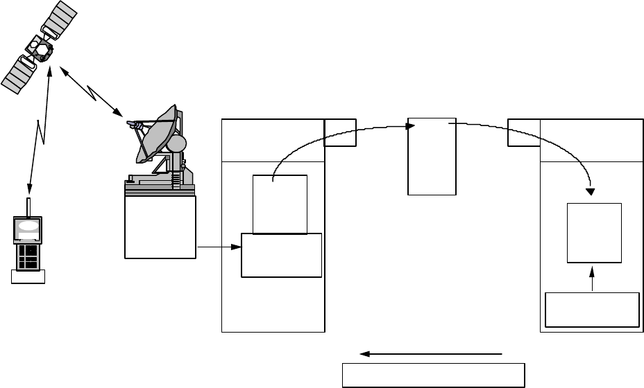
Description of the Globalstar System GS-TR-94-0001
Revision E
5-7
Home system SPC is
determined
SS7
2.The visited Gateway sends
a data message that
includes the User ID to the
HLR across the signaling
network.
3.
Home
Location
Register
(HLR)
Home Location
C 7
The Customer Profile is
scanned for an ID match
and the present GW
address is updated in
the HLR.
4.
Gateway (Visited)
Notes:
SPC = Switching Point Code
ID = Identification
MAP = Mobile Application Protocol
A record is created in the Visitor
Location Register (VLR) and
stored with profile information.
User is deregistered on shutdown
or upon command from the HLR
6.The subscriber profile is
returned to the Gateway.
User is deregistered from
previous VLR.
5.
Gateway
Authentication
Center
Data Messaage
includes User ID
1.
Visiting
Terminal
GSM User
SIM Card
GAI
Globalstar
Air
Interface
ANSIITU
CDMAGSM-A
Visitor
Location
Register
(VLR)
MSC
Mobile
Switching Center
GSM - MAP
Data
GSM - MAP
Data
ANSI-ITU
Protocol
Converter
SS-7
Kc Triplet
GSM Authenticates Subscriber
Reg GSM IS-41
Rev: 10/14/9 5
1
Figure 5-6 Registration of a European User in an IS-41 Environment2
5.3 Authentication Process3
Authentication verifies that the User Terminal is authorized to use the Globalstar resources. The4
Gateway will support authentication of the User Terminals; but, authentication is the responsibility of the5
home PLMN operator. The Gateway will transport authentication messages in the form required by the6
home PLMN operator. The Gateway will incorporate facilities to challenge, examine and update the7
authentication signature in the User Terminals.8
To achieve a consistent authentication scheme, the system adopted must be able to deal with each of the9
following situations:10
a. GSM User in GSM System11
b. IS-41 User in IS-41 System12
c. GSM User in IS-41 System13
d. IS-41 User in GSM System14
Where IS-41 User indicates a user whose Home system is based upon the IS-41 model and protocols15
(i.e. AMPS, IS-54, IS-95 and PSTN systems), and a GSM or IS-41 System indicates a serving16

Description of the Globalstar System GS-TR-94-0001
Revision E
5-8
Globalstar system where the mobility management facilities (HLR, VLR etc.) are GSM or IS-41-based,1
respectively.2
GSM User in GSM System: Here, all of the network components (MSC, HLR, VLR and AuC)3
should be able to communicate as in the standard GSM system. The challenge is reduced to a protocol4
inter working task on the Gateway-VLR and Gateway-MSC interfaces, and transport of GSM5
authentication data to and from the SIM. GSM roamers do not require a protocol converter. GSM6
uses the same SS-7 as the international signaling.7
IS-95 user in IS-95 (IS-41) System: All of the network components and protocols will operate in an8
IS-41 system. IS-41D supports and authentication center. Some networks may not support9
authentication.10
GSM User in IS-95 (IS-41) System: In this scenario, the various network components belong to11
different systems, as summarized in the following table:12
Component System
SIM GSM
Gateway/MSC IS-41
VLR IS-41
HLR/AuC GSM
13
The task that needs to be solved in this scenario is the retrieval and storage of authentication data from14
the HLR/AuC. For example, the triplets could be both requested and stored by the Gateway and the15
RAND and SRES parameters carried on the air interface to/from the SIM.16
The general message exchange is illustrated in Figure 5-7:17
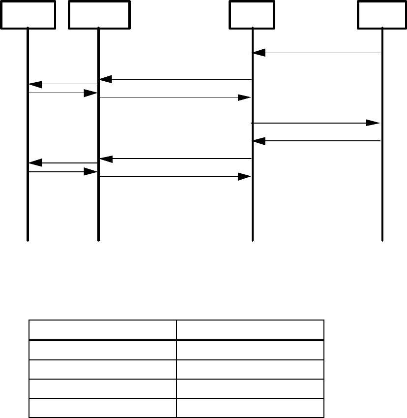
Description of the Globalstar System GS-TR-94-0001
Revision E
5-9
Subscriber
UnitHLR/AuC
Gateway
Insert Subscriber Data
Send Parameters
Send Parameters Response
Authentication Challenge
Authentication Challenge Response
Authentication Challenge
Authentication Challenge Response
SIM
RAND
SRES
RAND
SRES
File: GSM in IS41
1
Figure 5-7 Authentication for a GSM User in IS-41 System2
IS-95 User in GSM System: In this scenario, the various network components belong to different3
systems, as summarized in the following table:4
Component System
User Terminal IS-95/Globalstar
Gateway/MSC GSM
VLR GSM
HLR/AuC IS-41
5
In the IS-41 system, authentication is done mainly by the Gateway, with updates to authentication6
parameters periodically being retrieved from the AuC. The Gateway just has to recognize that the user7
understands IS-41 authentication, and not GSM and process messages appropriately.8
The messages and procedures for exchange of authentication data with the AuC/HLR is currently being9
reviewed by TIA for inclusion in IS-41C, and is summarized in TSB-51, Cellular Radio10
Telecommunications Inter systems Operation: Authentication, Signaling Message Encryption and Voice11
Privacy.12
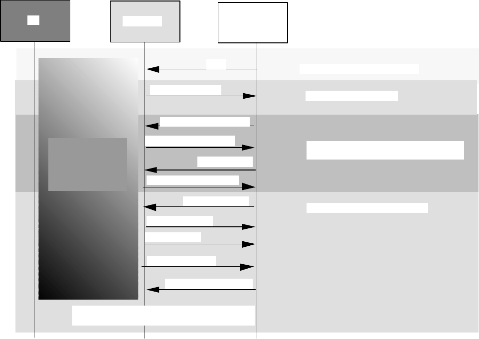
Description of the Globalstar System GS-TR-94-0001
Revision E
5-10
5.4 GSM - A Interface in Globalstar1
The Globalstar Gateway will interface with and MSC in the GSM environment in much the same way2
that any base station interfaces with the MSC. Figure 5-8 illustrates a typical GSM DTAP on Mobile3
Terminated Calls.4
UT GW (BSS) GSM MSC
Signalling Channel Request
CR (PAGE RESP)
DT1 (CPH MOD CMD)
DT1 (SETUP)
DT1 (CALL CONFIRM)
DT1 (ASS REQ)
DT1 (ASS COM)
Request for Service
Activates Encryption, Service
Option at Selector
Activates Traffic Voice Path
DT1 (CPH MOD COM)
DT1 (ALERT)
DT1 (CONNECT)
DT1(CONNECT ACK)
CDMA
Radio
Processing
Events
UDT
Stable 2-way Call
5
Figure 5-8 GSM DTAP on Mobile Terminated Call6
Figure 5-9 Illustrates GSM DTAP on a typical mobile originated call in Globalstar.7
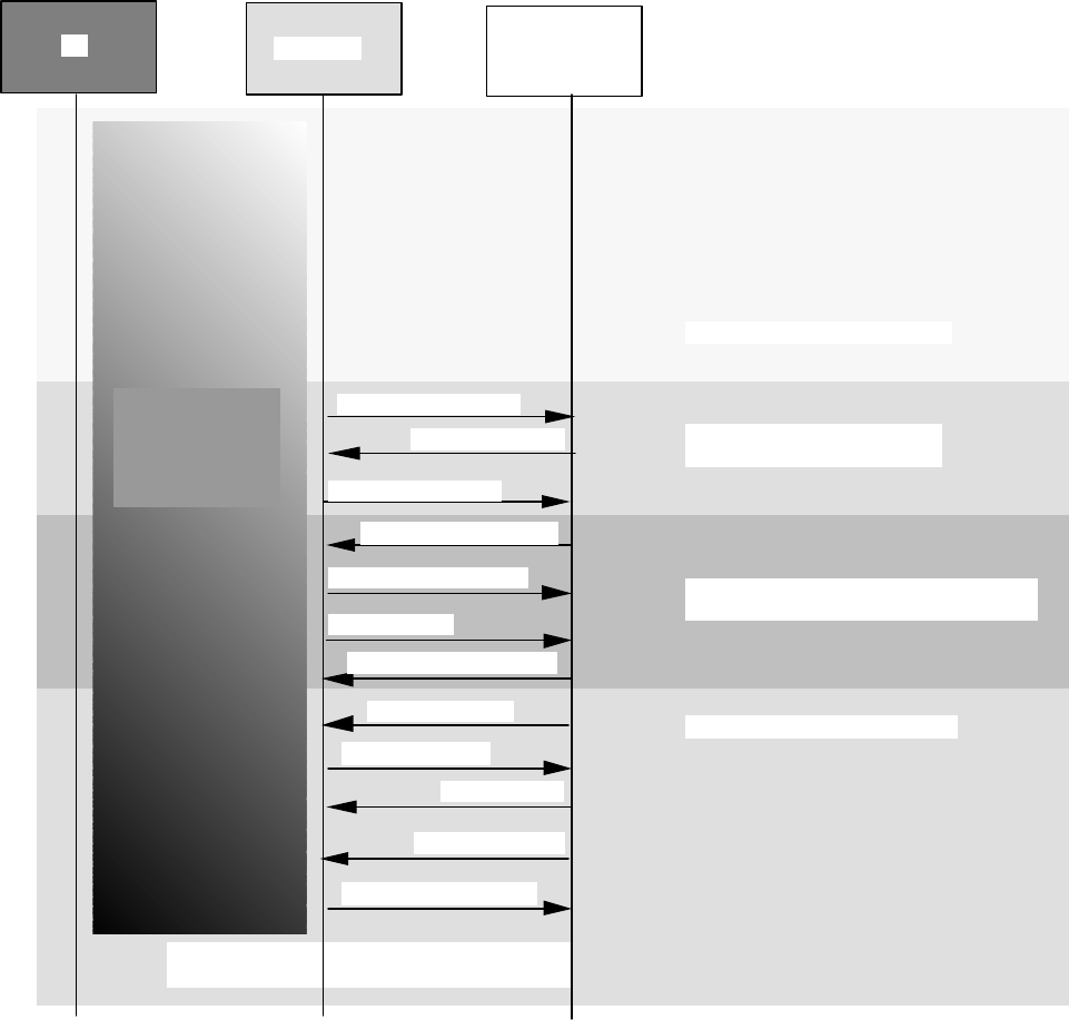
Description of the Globalstar System GS-TR-94-0001
Revision E
5-11
UTGW (BSS)GSM MSC
Signalling Channel Request
CR (CM SERV REQ)
CC (AUTH REQ)
DT1 (CPH MOD CMD)
DT1 (AUTH RESP)
DT1 (SETUP)
DT1 (CALL PROCEED)
DT1 (ASS REQ)
DT1 (ASS COM)
Request for Service &
Authentication
Activates Encryption, Service
Option at Selector
Activates Traffic Voice Path
DT1 (CPH MOD COM)
DT1 (ALERT)
DT1 (CONNECT)
DT1(CONNECT ACK)
Stable 2-way Call
CDMA
Radio
Processing
Events
1
Figure 5-9 GSM DTAP on Mobile Originated Call2
3
Description of the Globalstar System GS-TR-94-0001
Revision E
5-12
This page intentionally left blank.1
2
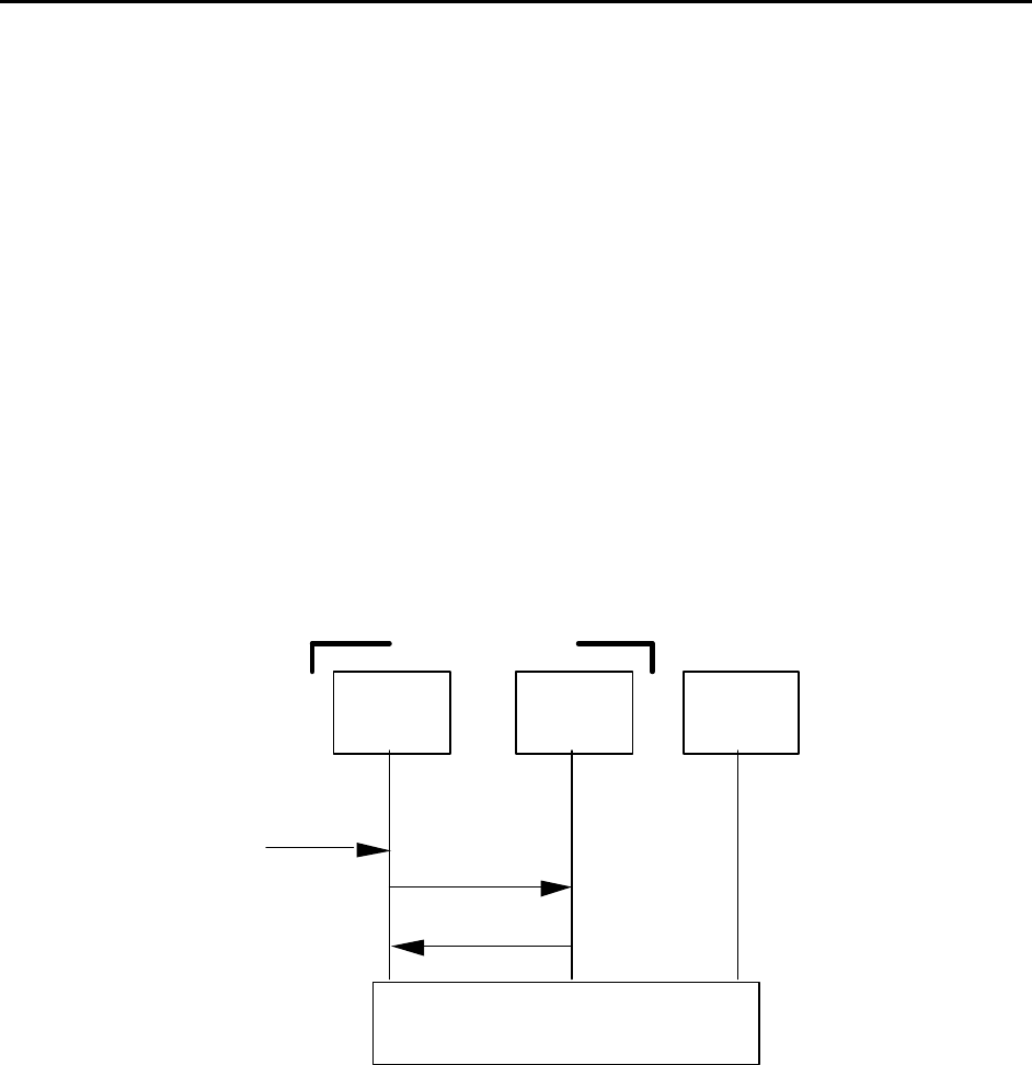
Description of the Globalstar System GS-TR-94-0001
Revision E
6-1
6. CALL PROCESSING1
6.1 Call Processing between Globalstar and PLMN2
This section discusses call processing between Globalstar and other PLMN systems. In Globalstar all3
User Terminals are treated as roaming from their terrestrial PLMN home system.4
Globalstar Only User Terminals: There are a series of User Terminals that are Globalstar Only. In5
these cases the service provider will incorporate the Globalstar Only User Terminals in the local Home6
Location Register (HLR). This applies to GSM or IS-41 HLRs. The Gateway will treat Globalstar7
Only UTs as Roamers.8
No Existing HLRs: In areas where there is no existing HLR, Globalstar may set up an HLR and9
function as the Service Provider.10
Emergency Calls: Globalstar will comply with the regulations for delivery of emergency calls.11
Mobile Originated Call: Figure 6-1 illustrates how a mobile originated call is processed.12
File: UT Origin
Switch
or MSC
CDMA VLR
Call Establishment
ORIGREQ
origreq
12
3
4
Gateway
Origination
Request
From User
13
Figure 6-1 Mobile Originated Call14
The following steps are performed:15
1. An Origination Request (ORIGREQ) is received from a User Terminal.16
2. An Origination Request INVOKE is sent from the Gateway (GW) to the VLR.17
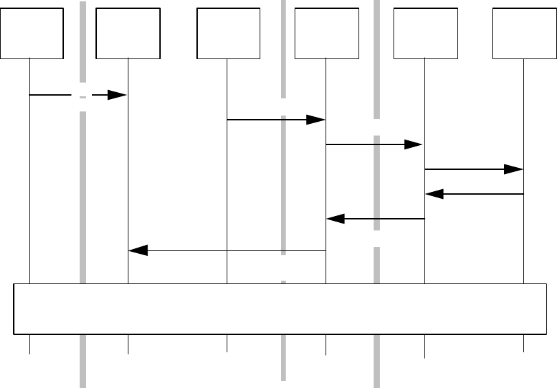
Description of the Globalstar System GS-TR-94-0001
Revision E
6-2
3. The Mobile is currently registered in this Visitor Location Register (VLR). The VLR1
responds with the Origination Request RETURN RESULT parameters.2
4. The call is established with the terrestrial system.3
Mobile Terminated: There are two scenarios for roaming call delivery. The first one is for a4
successful call (i.e. the user is idle). In the second case, the user is busy - this case is used to illustrate5
the possible invocation of a supplementary service such as Call Forward on Subscriber Busy.6
Roaming Call Delivery - Idle Case: Figure 6-2 illustrates a successful call connection.7
O
r
i
g
i
n
a
t
i
n
g
System
Switch
or MSCGWVLR HLRGWVLR
S
e
r
v
i
n
g
System
call
origination LOCREQ
ROUTREQ
routreq
routreq [TLDN]
locreq [TLDN]
1
2
3
4
5
6
7
8Call Setup
ROUTREQ
8
Figure 6-2 Roaming Call Delivery - Successful9
10
The following steps are performed:11
1. The switch attempts to deliver a call to the home Gateway of a mobile. In this scenario, the12
mobile is roaming, and so is not registered at the VLR of the home system.13
2. The VLR sends a Locate Request (LOCREQ) INVOKE to the Home Location Register14
(HLR) requesting the location of the mobile.15
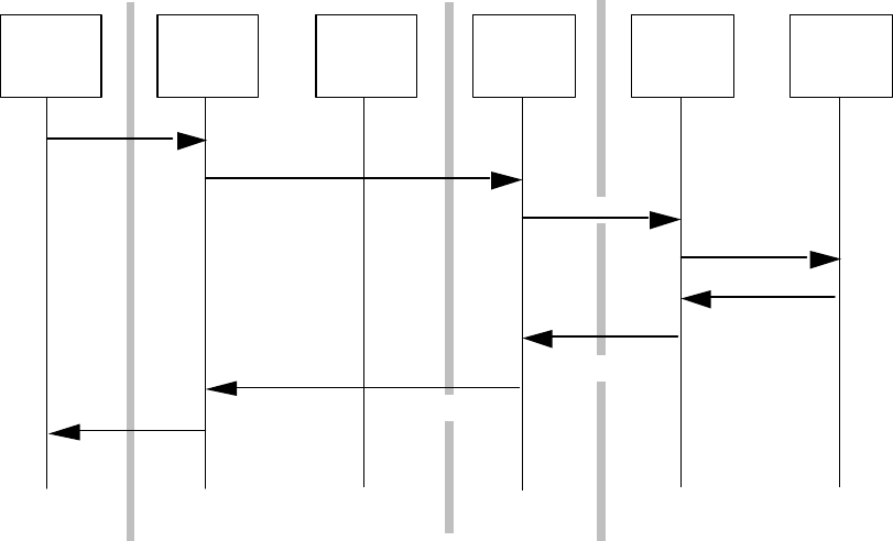
Description of the Globalstar System GS-TR-96-0021
Revision E
6-3
3. The HLR determines the serving system for the User Terminal and sends a Routing Request1
INVOKE to the serving VLR.2
4. The VLR sends a Routing Request (ROUTREQ) INVOKE to the Gateway to request the3
allocation of a Temporary Local Directory Number (TLDN) for the mobile.4
5. The Gateway allocates a TLDN and returns the result in a Routing Request RETURN5
RESULT.6
6. The VLR returns this TLDN to the HLR in the Routing Request RETURN RESULT.7
7. The HLR sends the TLDN to the originating VLR via Locate Request RETURN RESULT.8
8. The Gateway forwards the call to the destination Gateway (using the TLDN) and call setup is9
initiated with the serving Gateway.10
Roaming Call Delivery - Busy Case: This scenario illustrates the case where the called number is11
busy in a roaming system. The message exchange would be similar if features such as call forwarding12
were activated. Figure 6-3 is a case where the called number is busy.13
O
r
i
g
i
n
a
t
i
n
g
System
Switch
or MSCGWVLR HLRGWVLR
S
e
r
v
i
n
g
System
call
origination LOCREQ
ROUTREQ
ROUTREQ
routreq
routreq [busy]
locreq [busy]
1
2
3
4
5
6
7
busy 8
14
Figure 6-3 Roaming Call Delivery - Subscriber Busy15
Description of the Globalstar System GS-TR-94-0001
Revision E
6-4
The following steps are performed:1
1. The switch attempts to deliver a call to the home Gateway of a mobile. In this scenario, the2
mobile is roaming, and so is not registered at the VLR of the home system.3
2. The VLR sends a Locate Request (LOCREQ) INVOKE to the HLR requesting the4
location of the mobile.5
3. The HLR determines the serving system for the User Terminal and sends a Routing Request6
INVOKE to the serving VLR.7
4. The VLR sends a Routing Request INVOKE to the Gateway to request the allocation of a8
Temporary Local Directory Number (TLDN) for the mobile.9
6. The Gateway determines that the mobile is busy in another call and returns the result in a10
Routing Request RETURN RESULT.11
6. The VLR returns this notification to the HLR in the Routing Request RETURN RESULT.12
7. The HLR sends the result to the originating VLR via Locate Request RETURN RESULT,13
and the VLR forwards the result to the Gateway.14
8. The Gateway returns a busy indication to the network.15
Note that in the case of other call setup failures e.g. if Call Forwarding has been activated, the same16
scenario applies in principle, but the indication contained within the messages are different.17
Description of the Globalstar System GS-TR-96-0021
Revision E
6-5
6.2 TIA and ETSI Call Flow Examples1
This is an informative appendix which contains examples of call flows. The diagrams follow these2
conventions:3
• All messages are received without error4
• Receipt of messages is not shown except in the handoff examples5
• Acknowledgments are not shown6
• Authentication procedures are not shown7
• Encryption mode transitions are not shown8

Description of the Globalstar System GS-TR-94-0001
Revision E
6-6
1
User Terminal Gateway
•Detects user-initiated call
•Sends Origination Message >Access Channel >•Sets up Traffic Channel
•Begins sending null Traffic
Channel data
•Sets up Traffic Channel <Paging Channel <•Sends Channel Assignment
Message
•Receives N5m consecutive valid
frames
•Begins sending the Traffic Channel
preamble
•Acquires the Reverse Traffic
Channel
•Begins transmitting null Traffic
Channel data
<Forward Traffic
Channel
<•Sends Gateway Acknowledgment
Order
•Sends Service Request Message for
Service Option 1
>Reverse Traffic
Channel
>•Allocates resources for Service
Option 1
•Begins processing primary traffic in
accordance with Service Option 1
<Forward Traffic
Channel
<•Sends Service Connect Message
•Sends Service Connect Completion
Message
>Reverse Traffic
Channel
>
Optional Optional
•Sends Origination Continuation
Message
>Reverse Traffic
Channel
>
Optional Optional
•Applies ring back in audio path <Forward Traffic
Channel
<•Sends Alert With Information
Message (ring back tone)
Optional Optional
•Removes ring back from
audio path
<Forward Traffic
Channel
<•Sends Alert With Information
Message (tones off)
(User conversation) (User conversation)
2
Figure 6-4 Simple Call Flow, User Terminal Origination Example Using Service Option 13
(TIA Call Control Procedures)4
(Part 1 of 2)5
6

Description of the Globalstar System GS-TR-96-0021
Revision E
6-7
User Terminal Gateway
•Detects user-initiated call
•Sends Channel Request Message
indicating call origination and
service option requested
>Access Channel >•Sets up Traffic Channel
•Begins sending null Traffic
Channel data
•Sets up Traffic Channel <Paging Channel <•Sends Channel Assignment
Message
•Receives N5m consecutive valid
frames
•Begins sending the Traffic Channel
preamble
•Acquires the Reverse Traffic
Channel
•Begins transmitting null Traffic
Channel data
<Forward Traffic
Channel
<•Sends Gateway Acknowledgment
Order
•Sends ETSI Layer 3 Transport
Message containing CC Setup
message
>Reverse Traffic
Channel
>• Starts setting up a call
• See the note below <Forward Traffic
Channel
<•Sends ETSI Layer 3 Transport
Message containing CC Call-
Proceeding message
Note: The gateway and the user terminal follow the call establishment procedures as defined in section 5.2.1 of
ETS 300 557, GSM 04.08.
•Begins processing primary traffic in
accordance with Service Option 1
<Forward Traffic
Channel
<•Sends Service Connect Message
•Sends Service Connect Completion
Message
>Reverse Traffic
Channel
>
(User conversation) (User conversation)
1
Figure 6-5 Simple Call Flow, User Terminal Origination Example Using Service Option 12
(ETSI Call Control Procedures)3
(Part 2 of 2)4

Description of the Globalstar System GS-TR-94-0001
Revision E
6-8
1
User Terminal Gateway
<Paging Channel <•Sends General Page Message
•Sends Page Response Message >Access Channel >•Sets up Traffic Channel
•Begins sending null Traffic
Channel data
•Sets up Traffic Channel <Paging Channel <•Sends Channel Assignment
Message
•Receives N5m consecutive valid
frames
•Begins sending the Traffic Channel
preamble
•Acquires the Reverse Traffic
Channel
•Begins transmitting null Traffic
Channel data
<Forward Traffic
Channel
<•Sends Gateway Acknowledgment
Order
•Allocates resources for Service
Option 1
<Forward Traffic
Channel
<•Sends Service Request Message for
Service Option 1
•Sends Service Response Message
accepting Service Option 1
>Reverse Traffic
Channel
>
•Begins processing primary traffic in
accordance with Service Option 1
<Forward Traffic
Channel
<•Sends Service Connect Message
•Sends Service Connect Completion
Message
>Reverse Traffic
Channel
>
•Starts ringing <Forward Traffic
Channel
<•Sends Alert With Information
Message (ring)
•User answers call
•Stops ringing
•Sends Connect Order >Reverse Traffic
Channel
>
•Begins sending primary traffic
packets from the Service Option 1
application
(User conversation) (User conversation)
2
Figure 6-6. Simple Call Flow, User Terminal Termination Example Using Service Option3
1 (TIA Call Control Procedures)4(Part 1 of 2)5

Description of the Globalstar System GS-TR-96-0021
Revision E
6-9
1
User Terminal Gateway
<Paging Channel <•Sends General Page Message with
service option requested
•Sends Channel Request Message
indicating paging response
>Access Channel >•Sets up Traffic Channel
•Begins sending null Traffic
Channel data
•Sets up Traffic Channel <Paging Channel <•Sends Channel Assignment
Message
•Receives N5m consecutive valid
frames
•Begins sending the Traffic Channel
preamble
•Acquires the Reverse Traffic
Channel
•Begins transmitting null Traffic
Channel data
<Forward Traffic
Channel
<•Sends Gateway Acknowledgment
Order
•Sends ETSI Layer 3 Transport
Message containing RR Paging
Response message
>Reverse Traffic
Channel
>
•Starts alerting <Forward Traffic
Channel
<•Sends ETSI Layer 3 Transport
Message containing CC Setup
message
•Sends ETSI Layer 3 Transport
Message containing CC
Call_Confirmed message
>Reverse Traffic
Channel
>• See note below
Note: The gateway and the user terminal follow the call establishment procedures as defined in section 5.2.2 of
ETS 300 557, GSM 04.08.
•Begins processing primary traffic in
accordance with Service Option 1
<Forward Traffic
Channel
<•Sends Service Connect Message
•Sends Service Connect Completion
Message
>Reverse Traffic
Channel
>
(User conversation) (User conversation)
Figure 6-7 Simple Call Flow, User Terminal Termination Example Using Service Option 12
(ETSI Call Control Procedures)3
(Part 2 of 2)4

Description of the Globalstar System GS-TR-94-0001
Revision E
6-10
1
User Terminal Gateway
•Detects user-initiated disconnect
•Sends Release Order >Reverse Traffic
Channel
>
<Forward Traffic
Channel
<•Sends Release Order
•Enters the System Determination
Substate of the User Terminal
Initialization State
2
Figure 6-8. Simple Call Flow, User Terminal Initiated Call Disconnect Example (TIA Call3
Control Procedures)4(Part 1 of 2)5
6
User Terminal Gateway
•Detects user-initiated disconnect
•Sends ETSI Layer 3 Transport
Message containing CC Disconnect
message
>Reverse Traffic
Channel
>• Initiates procedures to clear the
network connection
• Releases the MM connection <Forward Traffic
Channel
<• Sends ETSI Layer 3 Transport
Message containing CC Release
message
• Sends ETSI Layer 3 Transport
Message containing CC Release
Complete message1
>Reverse Traffic
Channel
>• Releases the MM connection
• Releases the RR connection (Traffic
Channel)
<Forward Traffic
Channel
<•Sends Release Order
•Enters the System Determination
Substate of the User Terminal
Initialization State
Figure 6-9 Simple Call Flow, User Terminal Initiated Call Disconnect Example (ETSI Call7
Control Procedure)8
(Part 2 of 2)9
1For more details see call release procedures defined in section 5.4.3 of ETS 300 557, GSM 04.08.

Description of the Globalstar System GS-TR-96-0021
Revision E
6-11
1
2
3
4
User Terminal Gateway
•Detects call disconnect
<Forward Traffic
Channel
<•Sends Release Order
•Sends Release Order >Reverse Traffic
Channel
>
•Enters the System Determination
Substate of the User Terminal
Initialization State
5
Figure 6-10. Simple Call Flow, Gateway Initiated Call Disconnect Example (TIA Call6
Control Procedures)7(Part 1 of 2)8

Description of the Globalstar System GS-TR-94-0001
Revision E
6-12
1
User Terminal Gateway
•Detects call disconnect
<Forward Traffic
Channel
<• Sends ETSI Layer 3 Transport
Message containing CC
Disconnect message
• Sends ETSI Layer 3 Transport
Message containing CC Release
message
>Reverse Traffic
Channel
>• Releases the MM connection
• Releases the MM connection <Forward Traffic
Channel
<• Sends ETSI Layer 3 Transport
Message containing CC Release2
Complete message
• Releases the RR connection (Traffic
Channel)
<Forward Traffic
Channel
<•Sends Release Order
•Enters the System Determination
Substate of the User Terminal
Initialization State
2
Figure 6-11 Simple Call Flow, Gateway Initiated Call Disconnect Example (ETSI Call3
Control Procedure)4
(Part 2 of 2)5
6
2 For more details see the call release procedures as defined in section 5.4.4 of ETS 300 557, GSM 04.08.

Description of the Globalstar System GS-TR-96-0021
Revision E
6-13
1
User Terminal Gateway
(User conversation) (User conversation)
•Detects request for third party to be
added to conversation
•Sends Flash With Information
Message (dialed digits)
>Reverse Traffic
Channel
>•Mutes speech
Optional Optional
•Applies ring back in audio path <Forward Traffic
Channel
<•Sends Alert With Information
Message (ring back tone)
(Called party answers)
Optional Optional
•Removes ring back tone from audio
path
<Forward Traffic
Channel
<•Sends Alert With Information
Message (tones off)
•Unmutes speech from added party
(Two-way conversation with added
party; original party
held)
(Two-way conversation with added
party; original party held)
•Detects user request to establish
three-way conversation
•Sends Flash With Information
Message
>Reverse Traffic
Channel
>•Reconnects original party
(Three-way conversation) (Three-way conversation)
2
Figure 6-12. Simple Call Flow, Three-Party Calling Example (TIA Call Control3
Procedures)4

Description of the Globalstar System GS-TR-94-0001
Revision E
6-14
1
User Terminal Gateway
(User conversation with first party) (User conversation with first party)
•Detects incoming call
Optional Optional
•Applies call waiting tone in audio
path
<Forward Traffic
Channel
<•Sends Alert With Information
Message (call waiting tone)
•Detects user request to change
parties
•Sends Flash With Information
Message
>Reverse Traffic
Channel
>•Mutes speech path to first party,
connects second party
(User conversation with second party;
first party held)
(User conversation with second
party; first party held)
•Detects user request to change
parties
•Sends Flash With Information
Message
>Reverse Traffic
Channel
>•Mutes speech path to second
party, connects first party
(User conversation with first party;
second party held)
(User conversation with first party;
second party held)
2
Figure 6-13. Simple Call Flow, Call-Waiting Example (TIA Call Control Procedures)3
4
Figure 6-14 illustrates call processing operations during a soft handoff from pilot A to pilot B. Figure 6-5
15 illustrates call processing operations during a sequential soft handoff in which the user terminal is6
transferred from a pair of pilots A and B through a pair of pilots A and C to pilot C. All the handoff call7
processing procedures described below are the same for both the TIA and the ETSI call control and8
mobility management procedures.9

Description of the Globalstar System GS-TR-96-0021
Revision E
6-15
1
User Terminal Gateway
(User conversation using A) (User conversation using A)
•Sends Pilot Strength Measurement
Message
>Reverse Traffic
Channel
>•Receives Pilot Strength
Measurement Message
GW decides to begin handoff to
channel B.
•Begins transmitting traffic on the
Forward Traffic Channel on B
•Receives Handoff Direction
Message
<Forward Traffic
Channel
<•Sends Handoff Direction Message
to use A and B
•Acquires B; begins using Active
Set {A,B}
•Sends Handoff Completion
Message
>Reverse Traffic
Channel
>•Receives Handoff Completion
Message
•Handoff drop timer of pilot A
expires
•Sends Pilot Strength Measurement
Message
>Reverse Traffic
Channel
>•Receives Pilot Strength
Measurement Message
GW decided to cancel channel A
•Receives Handoff Direction
Message
<Forward Traffic
Channel
<•Sends Handoff Direction Message
to use B only
•Stops diversity combining; begins
using Active Set {B}
•Sends Handoff Completion
Message
>Reverse Traffic
Channel
>•Receives Handoff Completion
Message
•Stops transmitting on the Forward
Traffic Channel using A
(User conversation using B) (User conversation using B)
2
Figure 6-14. Call Processing During Soft Handoff3

Description of the Globalstar System GS-TR-94-0001
Revision E
6-16
1
User Terminal Gateway
(User conversation using
A and B)
(User conversation using
A and B)
•Sends Pilot Strength Measurement
Message
>Reverse Traffic
Channel
>•Receives Pilot Strength
Measurement Message, determines
that new Active Set should contain
B and C
•Begins transmitting traffic on the
Forward Traffic Channel using C
•Receives Handoff Direction
Message
<Forward Traffic
Channel
<•Sends Handoff Direction Message
to use B and C
•Stops diversity combining A and B;
starts diversity combining B and C
•Sends Handoff Completion
Message
>Reverse Traffic
Channel
>•Receives Handoff Completion
Message
•Stops transmitting on the Forward
Traffic Channel using A
•Sends Pilot Strength Measurement
Message
>Reverse Traffic
Channel
>•Receives Pilot Strength
Measurement Message
(Continues) (Continues)
2
Figure 6-15. Call Processing During Sequential Soft Handoff3(Part 1 of 2)4

Description of the Globalstar System GS-TR-96-0021
Revision E
6-17
1
User Terminal Gateway
(Continues) (Continues)
•Receives Handoff Direction
Message
<Forward Traffic
Channel
<•Sends Handoff Direction Message
to use C only
•Stops diversity combining; begins
using Active Set {C}
•Sends Handoff Completion
Message
>Reverse Traffic
Channel
>•Receives Handoff Completion
Message
•Stops transmitting on the Forward
Traffic Channel using B
(User conversation using C) (User conversation using C)
2
Figure 6-16 Call Processing During Sequential Soft Handoff3
(Part 2 of 2)4
5
6
7
8
9