Gogo Business Aviation P24486 GVPU User Manual GVPU IM D18340 ForFCCFilingx
Gogo Business Aviation LLC GVPU GVPU IM D18340 ForFCCFilingx
Users Manual Revised 060415
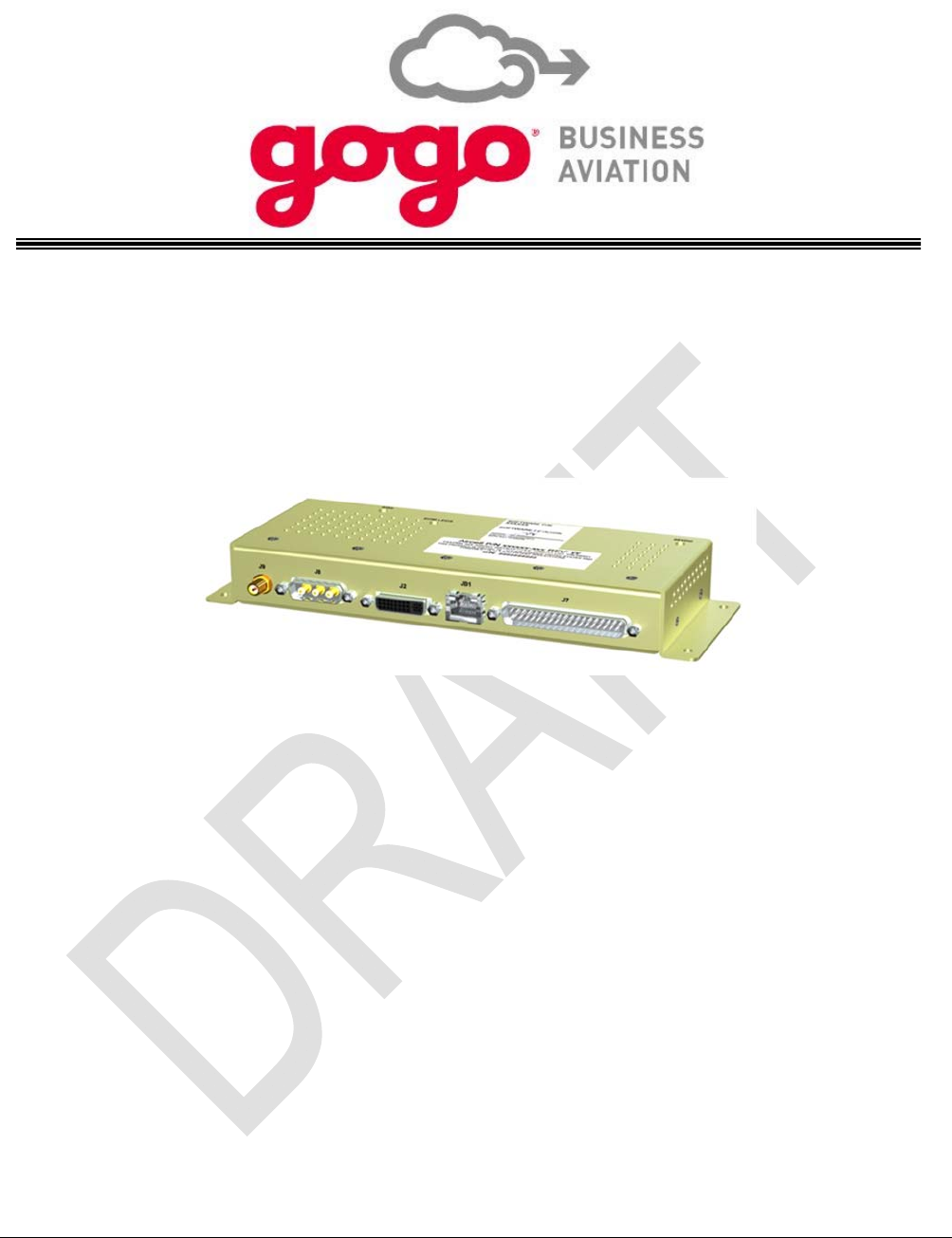
Gogo Video Processing Unit (GVPU)
Installation Manual
Installation Manual part number D18340
Revision A, May 2015
Gogo Business Aviation
105 Edgeview Drive, Suite 300
Broomfield, CO 80021
Distribution Statement: This publication is for the Gogo Video Processing Unit product only and is to
be used by customers and authorized Gogo Business Aviation
agents only. Send requests for
additional copies of this document to Gogo Business Aviation Customer Service at 1-888-286-9876.

Page i
Gogo Business Aviation confidential and proprietary D18340-A, May 2015
PROPRIETARY NOTICE
This document and the information disclosed herein are proprietary data of Gogo Business Aviation.
Neither this document nor the information contained herein shall be used, reproduced, or disclosed to
others without prior written authorization of Gogo Business Aviation, except to the extent required for
installation of recipient’s equipment.
Notice
Freedom of Information Act (5 USC 552) and Disclosure of
Confidential Information Generally (18 USC 1905)
Gogo Business Aviation is furnishing this document in confidence. The information disclosed here falls
within exemption (b)(4) of USC 552 and the prohibitions of 18 USC 1905. For further information, please
contact:
Gogo Business Aviation
105 Edgeview Drive, Suite 300
Broomfield, CO 80021
Telephone: (303) 301-0278
FAX: (303) 301-0279
© 2015 Gogo Business Aviation
All Rights Reserved
Information in this document is subject to change without notice and does not represent a commitment on
the part of Gogo Business Aviation.
Trademark Acknowledgements
Gogo Business Aviation is a registered trademark, and Gogo Biz is a trademark, of Gogo Business
Aviation and its affiliates. All rights reserved.
Trademarks and service marks owned by third parties are the property of their respective owners.

Page ii
Gogo Business Aviation confidential and proprietary D18340-A, May 2015
RECORD OF REVISIONS
REVISION DESCRIPTION RELEASE
DATE RELEASED
BY
A Initial Release May 2015 Gogo
Business
Aviation

Page iii
Gogo Business Aviation confidential and proprietary D18340-A, May 2015
RECORD OF TEMPORARY REVISIONS
TEMPORARY
REV. NO. PAGE
NUMBER ISSUE DATE BY DATE
REMOVED BY

Page iv
Gogo Business Aviation confidential and proprietary D18340-A, May 2015
TABLE OF CONTENTS
Subject Page
PROPRIETARY NOTICE ............................................................................................................................... i
RECORD OF REVISIONS ............................................................................................................................ ii
RECORD OF TEMPORARY REVISIONS ................................................................................................... iii
TABLE OF CONTENTS .............................................................................................................................. iv
LIST OF FIGURES ..................................................................................................................................... vii
LIST OF TABLES ...................................................................................................................................... viii
1.0INTRODUCTION ........................................................................................................................ 1-1
1.1.General ...................................................................................................................................... 1-1
1.2.Unpacking ................................................................................................................................. 1-2
1.3.Planning .................................................................................................................................... 1-2
1.4.List of Abbreviations and Acronyms ..................................................................................... 1-2
1.5.Advisories ................................................................................................................................. 1-3
1.6.FCC Compliance ...................................................................................................................... 1-4
1.7.List of Related Publications .................................................................................................... 1-6
2.0DESCRIPTION AND OPERATION ........................................................................................... 2-1
2.1.Introduction and Overview ...................................................................................................... 2-1
2.2.GVPU Indicators ....................................................................................................................... 2-3
2.3.GVPU Power ............................................................................................................................. 2-3
2.4.Component Part Numbers ....................................................................................................... 2-3
2.5.General Purpose Input/Output ................................................................................................ 2-3
2.6.Physical Characteristics .......................................................................................................... 2-3
3.0INSTALLATION PROCEDURES .............................................................................................. 3-1
3.1.Planning .................................................................................................................................... 3-1
3.2.Equipment Location ................................................................................................................. 3-1
3.3.Equipment Configuration ........................................................................................................ 3-1
3.3.1.Considerations Regarding Current System ...................................................................... 3-2
3.3.2.Sample Configurations ........................................................................................................ 3-2
3.3.2.1.Single Digital Video Source ............................................................................................ 3-2
3.3.2.2.GVPU as an Input Source to the CMS/A/V Distribution System .................................. 3-3
3.3.2.3.Multiple Video Sources; GVPU after CMS ..................................................................... 3-4
3.4.Cable Routing ........................................................................................................................... 3-5
3.5.Cabling ...................................................................................................................................... 3-6
3.6.Antenna Mounting .................................................................................................................... 3-8
3.7.Remote Ground Maintenance Ethernet ................................................................................. 3-8
4.0SETUP, CONFIGURATION, and FUNCTIONAL TESTING ..................................................... 4-1
4.1.Introduction .............................................................................................................................. 4-1
4.2.Test Results .............................................................................................................................. 4-1
4.3.Control and Operation ............................................................................................................. 4-1
4.4.GVPU Configuration ................................................................................................................ 4-1
4.4.1.GVPU Address Scheme ....................................................................................................... 4-1

Page v
Gogo Business Aviation confidential and proprietary D18340-A, May 2015
4.4.2.Accessing the GVPU Configuration Page ......................................................................... 4-2
4.4.2.1.GVPU Configuration ........................................................................................................ 4-4
4.4.2.2.Player ID: ........................................................................................................................... 4-4
4.4.2.3.Player Name: ..................................................................................................................... 4-5
4.4.2.4.Connection Type: ............................................................................................................. 4-6
4.4.2.5.Wi-Fi: Enable/Disable ...................................................................................................... 4-7
4.4.2.6.Wi-Fi SSID: ........................................................................................................................ 4-8
4.4.2.7.Wi-Fi Security: .................................................................................................................. 4-8
4.4.2.8.Wi-Fi Credentials: ............................................................................................................. 4-8
4.4.2.9.Audio Setting: ................................................................................................................... 4-9
4.4.2.10.Video Setting: ............................................................................................................. 4-10
4.4.2.11.Show Advanced Options ........................................................................................... 4-11
4.4.2.12.Update ......................................................................................................................... 4-12
4.4.3.GVPU Configuration – Advanced Options ...................................................................... 4-13
4.4.3.1.Audio Level: .................................................................................................................... 4-13
4.4.3.2.Wi-Fi Kill Switch: ............................................................................................................ 4-14
4.4.3.3.Wi-Fi Kill Switch Frequency: ......................................................................................... 4-15
4.4.3.4.Heartbeat Frequency: .................................................................................................... 4-16
4.4.3.5.Heartbeat Server Host: .................................................................................................. 4-16
4.4.3.6.Heartbeat Server Port: ................................................................................................... 4-16
4.4.3.7.Status Bar: ...................................................................................................................... 4-17
4.4.3.8.Remote Logging: ............................................................................................................ 4-18
4.4.3.9.Remote Logging Level: ................................................................................................. 4-19
4.4.3.10.A/V Bypass at Bootup: .............................................................................................. 4-20
4.4.3.11.Update ......................................................................................................................... 4-21
4.5.Functional Testing ................................................................................................................. 4-22
4.5.1.System Operational Checks .............................................................................................. 4-22
4.5.2.Required System Components ......................................................................................... 4-22
4.5.3.Operational Check: Configuration ................................................................................... 4-22
4.5.4.Operational Check: Streaming Video .............................................................................. 4-23
4.5.5.Operational Check: Composite Video ............................................................................. 4-23
4.6.Maintenance ............................................................................................................................ 4-24
4.6.1.Inspection ........................................................................................................................... 4-24
4.6.2.Mandatory Replacement Time .......................................................................................... 4-24
5.0CLEANING ................................................................................................................................. 5-1
5.1.Introduction .............................................................................................................................. 5-1
5.2.Recommended Cleaning Materials ........................................................................................ 5-1
5.3.Procedure .................................................................................................................................. 5-1
6.0FITS AND CLEARANCES ......................................................................................................... 6-1
6.1.GVPU ......................................................................................................................................... 6-1
7.0SYSTEM SPECIFICATIONS ..................................................................................................... 7-1
7.1.Purpose ..................................................................................................................................... 7-1

Page vi
Gogo Business Aviation confidential and proprietary D18340-A, May 2015
7.2.Product Definition .................................................................................................................... 7-1
7.3.Associated Reference Documents ......................................................................................... 7-1
7.4.Technical Specifications ......................................................................................................... 7-1
7.4.1.GVPU ..................................................................................................................................... 7-1
8.0SPECIAL TOOLS, FIXTURES, AND EQUIPMENT .................................................................. 8-1
8.1.Introduction .............................................................................................................................. 8-1
8.2.GVPU Configuration using Ethernet Interface ...................................................................... 8-1
9.0PARTS LIST .............................................................................................................................. 9-1
9.1.Introduction .............................................................................................................................. 9-1
10.0WIRING DIAGRAMS .................................................................................................................... 1
10.1.Wiring Diagrams .......................................................................................................................... 1
10.2.GVPU ............................................................................................................................................ 1
Appendix A: Troubleshooting Procedures .......................................................................................... A-1
Appendix B: Instructions for Continued Airworthiness .................................................................... B-1

Page vii
Gogo Business Aviation confidential and proprietary D18340-A, May 2015
LIST OF FIGURES
Figure Title Page
The video content is streamed from the UCS content server to the GVPU via a wired Ethernet port.
The GVPU outputs a composite video signal and/or an HDMI signal containing video data to the
cabin monitor based on user selection. The composite video signal exits via a D-sub connector.
The HDMI link uses a DVI-style connector which can be secured using the fixed jackscrews for
use in a vibrating environment. .............................................................................................................. 2-1
Figure 2.2.Sample GVPU Installation ............................................................................................... 2-2
Figure 3.1.Single Digital Video Source ............................................................................................ 3-3
Figure 3.2.Multiple Video Sources, GVPU Before CMS .................................................................. 3-4
Figure 3.3.Multiple Video Sources, GVPU After CMS ..................................................................... 3-5
Figure 4.1.GVPU Configuration Page ............................................................................................... 4-3
Figure 4.4.Player ID ............................................................................................................................ 4-4
Figure 4.5.Player Name ...................................................................................................................... 4-5
Figure 4.6.Connection Type .............................................................................................................. 4-6
Figure 4.7.Wi-Fi: Enable/Disable ...................................................................................................... 4-7
Figure 4.8.Wi-Fi SSID/ Security/ Credentials ................................................................................... 4-8
Figure 4.9.Audio Setting .................................................................................................................... 4-9
Figure 4.10.Video Setting .............................................................................................................. 4-10
Figure 4.11.Show Advanced Options ........................................................................................... 4-11
Figure 4.12.Update ......................................................................................................................... 4-12
Figure 4.13.Audio Level ................................................................................................................. 4-13
Figure 4.14.Wi-Fi Kill Switch ......................................................................................................... 4-14
Figure 4.15.Wi-Fi Kill Switch Frequency ...................................................................................... 4-15
Figure 4.16.Heartbeat Frequency/Host/Port ................................................................................ 4-16
Figure 4.17.Status Bar ................................................................................................................... 4-17
Figure 4.18.Remote Logging ......................................................................................................... 4-18
Figure 4.19.Remote Logging Level ............................................................................................... 4-19
Figure 4.20.A/V Bypass at Bootup ................................................................................................ 4-20
Figure 4.21.Update ......................................................................................................................... 4-21
Figure A-1 GVPU Configuration Page ....................................................................................................... 3

Page viii
Gogo Business Aviation confidential and proprietary D18340-A, May 2015
LIST OF TABLES
Table Title Page
Table 2.1.GVPU Equipment Installed .............................................................................................. 2-3
Table 4.1.Reference GPIO IP Address Mapping ............................................................................ 4-2

Page ix
Gogo Business Aviation confidential and proprietary D18340-A, May 2015
This Page Intentionally Blank

Introduction, Section 1 Page 1-1
Gogo Business Aviation confidential and proprietary D17502-C, May 2015
1.0 INTRODUCTION
1.1. General
This installation manual (Gogo Video Processing Unit (GVPU), manual number D18340) provides the
required instructions to install the GVPU.
The GVPU is an airborne-certified, Android-based video player device which serves as a sub-system of
the Universal Cabin System (UCS) In-Flight Entertainment (IFE) system. Streaming media from the UCS
content server is input to the GVPU via Ethernet Protocol and converted to a display format compatible
with a cabin monitor. It is also capable of taking composite video input from devices such as Video
Cassette Recorders (VCR), Digital Video Disk (DVD) players, or an Airshow system if the aircraft is so
equipped. Selection of the video source can be controlled remotely.
The GVPU output is typically connected to a cabin monitor or Audio-Video distribution system. High-
Definition Multimedia Interface (HDMI) video output is available in both “1080P” and “720P”. Composite
video output is also available.
A composite video bypass function is available wherein a composite video input is always present at the
video output connector unless a movie or other digital video content is selected and playing.
A separate analog audio input connection provides for connection to a Cabin Management System
(CMS), an Audio-Video (A/V) Distribution system, or other audio source. Audio output is available in
either the Sony/Philips Digital Interface Format (S/PDIF) or analog format depending on the configuration
of the audio portion of the aircraft IFE system.
General Installation Notes
The GVPU must be installed inside the aircraft pressure vessel.
Install the GVPU unit in locations that are free of water or other fluids, whether by direct contact or
condensation.
The GVPU is convection-cooled only and does not require any forced air or other form of cooling.
Plan the installation to locate the GVPU near the cabin monitor to which it will be connected.
NOTE
The material in this manual is subject to change. Before planning or performing any installation operation,
check with the www.my.gogoair.com website to verify this manual is complete and is the latest revision.
The Record of Revisions, Record of Temporary Revisions, Service Bulletin List, and List of Effective Pages
found at the front of this manual must match that issued as current by Gogo Business Aviation.
www.my.gogoair.com will have additional information that may be useful such as, Technical Bulletins and
Tech Tips and Installation and Troubleshooting Tips.

Introduction, Section 1 Page 1-2
Gogo Business Aviation confidential and proprietary D17502-C, May 2015
Gogo Business Aviation welcomes your comments, suggestions, and corrections concerning this manual.
Please include in your correspondence the publication number, equipment part number, page or figure
number, and a brief description of any problem or consideration you noted. Please send your comments
to:
Gogo Business Aviation
Sales Engineering Technical Publications
105 Edgeview Drive, Suite 300
Broomfield, Colorado 80021
1.2. Unpacking
Unpack the equipment carefully to save and ensure the integrity of the shipping package. Inspect each
component for possible shipping damage. Report any damage to Gogo Business Aviation immediately.
Use original packing material to return equipment to Gogo Business Aviation.
1.3. Planning
Proper and careful planning is essential for reliable system performance and ease of maintenance. The
following are some considerations to follow when planning the installation:
Study this manual carefully to get the complete picture of the installation process.
Visit www.my.gogoair.com for additional information that may be useful, such as Technical Bulletins
and Tech Tips and Installation and Troubleshooting Tips.
Plan the location of the required equipment to ensure that the cable restrictions are met.
Check cable routing, connector access (90 degree or straight), and determine cable lengths.
Ensure easy accessibility to connectors for future repairs.
1.4. List of Abbreviations and Acronyms
A Ampere LRU Line Replaceable Unit
AC Advisory Circular mA milliampere = .001 of an ampere
AWG American Wire Gauge MHz Megahertz
CFR Code of Federal Regulations PED Personal Electronic Device
CNS Cabin Management System P/N Part Number
dB Decibel PoE Power Over Ethernet
DC Direct Current P/N Part Number
DHCP Dynamic Host Configuration Protocol RF Radio Frequency
FAA Federal Aviation Administration RMA Return Material Authorization
FAR Federal Aviation Regulation SAE Society of Automotive Engineers
FCC Federal Communications Commission SIP Session Initiation Protocol
GHz Gigahertz S/PDIF Sony/Phillips Digital Interface Format
GPIO General Purpose Input/Output STC Supplemental Type Certificate
GUI Graphical User Interface TC Type Certificate
GVPU Gogo Video Processing Unit V Volts
HD High Definition VDC Volts Direct Current
HDMI High Definition Multimedia Interface WAP Wireless Access Point
ICD Interface Control Drawing Wi-Fi Wireless Fidelity
Introduction, Section 1 Page 1-3
Gogo Business Aviation confidential and proprietary D17502-C, May 2015
IP Internet Protocol
LAN Local Area Network
LED Light Emitting Diode
DO-160G Environmental conditions and test procedures for airborne equipment development are
produced by RTCA. The Federal Aviation Administration (FAA) generally accepts these
conditions and procedures.
1.5. Advisories
WARNING
Statements in this Section contain critical safety information. Read these statements carefully
before installing this unit.
WARNING
Observe standard safety precautions and wear safety glasses to prevent personal injury while
installing this unit in the aircraft.
WARNING
Shut off power before connecting or disconnecting the GVPU as voltage transients may damage
the unit or the interface wiring.
WARNING
Follow the manufacturer’s safety guidelines when using any solvents, epoxies, flammable liquids,
or any other materials during the installation processes. Some of these products are toxic to the
skin, eyes, and respiratory tract. Avoid prolonged contact and use only in well-ventilated areas.
WARNING
Components or subassemblies found in this unit may contain materials such as beryllium oxide,
acids, lithium, radioactive material, mercury, etc. that can be hazardous to your health. If the
component enclosure seal is broken, precautions must be taken against personal contact or
inhalation in accordance with Occupational Safety and Health Administration (OSHA)
requirements 29 Code of Federal Regulations (CFR) 1910.1000 or superseding documents. Any
alteration of this product voids the FAA certification and the Gogo Business Aviation
warranty.
CAUTION
Use Isopropyl alcohol carefully as it may react with some plastics in the area. Isopropyl alcohol
should be used to clean connector contacts and metal parts (if required).

Introduction, Section 1 Page 1-4
Gogo Business Aviation confidential and proprietary D17502-C, May 2015
1.6. FCC Compliance
Federal Communication Commission Interference Statement
This equipment has been tested and found to comply with the limits for a Class B digital device, pursuant
to Part 15 of the FCC Rules. These limits are designed to provide reasonable protection against harmful
interference in a residential installation. This equipment generates uses and can radiate radio frequency
energy and, if not installed and used in accordance with the instructions, may cause harmful interference
to radio communications. However, there is no guarantee that interference will not occur in a particular
installation. If this equipment does cause harmful interference to radio or television reception, which can
be determined by turning the equipment off and on, the user is encouraged to try to correct the
interference by one of the following measures:
Reorient or relocate the Wi-Fi antenna.
Increase the separation between the equipment and the affected device.
Connect the equipment to a different poser source from the GVPU.
Consult the dealer or an experienced radio/TV technician for help.
FCC Caution: Any changes or modifications not expressly approved by the party responsible for
compliance could void the user's authority to operate this equipment.
This device complies with Part 15 of the FCC Rules. Operation is subject to the following two conditions:
(1) this device may not cause harmful interference, and (2) this device must accept any interference
received, including interference that may cause undesired operation.
IMPORTANT NOTICE:
FCC Radiation Exposure Statement:
This equipment complies with FCC radiation exposure limits set forth for an uncontrolled environment.
This equipment should be installed and operated with minimum distance 20 cm between the radiator &
your body.
This transmitter must not be co-located or operating in conjunction with any other antenna or transmitter.
Operations in the 5.15-5.25GHz band are restricted to indoor usage only.
Industry Canada statement:
This device complies with RSS-210 of the Industry Canada Rules. Operation is subject to the following
two conditions: (1) This device may not cause harmful interference, and (2) this device must accept any
interference received, including interference that may cause undesired operation.
Ce dispositif est conforme à la norme CNR-210 d'Industrie Canada applicable aux appareils radio
exempts de licence. Son fonctionnement est sujet aux deux conditions suivantes: (1) le dispositif ne doit
pas produire de brouillage préjudiciable, et (2) ce dispositif doit accepter tout brouillage reçu, y compris
un brouillage susceptible de provoquer un fonctionnement indésirable.
Radiation Exposure Statement:
This equipment complies with IC radiation exposure limits set forth for an uncontrolled environment. This
equipment should be installed and operated with minimum distance 20 cm between the radiator & your
body.

Introduction, Section 1 Page 1-5
Gogo Business Aviation confidential and proprietary D17502-C, May 2015
Déclaration d'exposition aux radiations:
Cet équipement est conforme aux limites d'exposition aux rayonnements IC établies pour un
environnement non contrôlé. Cet équipement doit être installé et utilisé avec un minimum de 20 cm de
distance entre la source de rayonnement et votre corps.
Warning:
(i) Devices operating in the band 5 150-5 250 MHz is only for utilization in order to reduce the risk of
harmful interference to mobile satellite systems using the same channels;
(ii) In addition, users should also be aware that users of high-power radars are designated primary users
(i.e., they have priority) of the bands 5 250-5 350 MHz and 5 650-5 850 MHz and these radars could
cause interference and/or damage to LE-LAN devices.
Avertissement:
(i) Les dispositifs fonctionnant dans la bande 5 150-5 250 MHz sont réservés uniquement pour une
utilization à l’intérieur afin de réduire les risques de brouillage préjudiciable aux systèmes de satellites
mobiles utilisant les mêmes canaux;
(ii) De plus, les utilisateurs devraient aussi être avisés que les utilisateurs de radars de haute puissance
sont désignés utilisateurs principaux (c.-à-d., qu’ils ont la priorité) pour les bandes 5 250-5 350 MHz et 5
650-5 850 MHz et que ces radars pourraient causer du brouillage et/ou des dommages aux dispositifs
LAN-EL.
This device has been designed to operate with an antenna having a maximum gain of 4 dBi. Antenna
having a higher gain is strictly prohibited per regulations of Industry Canada. The required antenna
impedance is 50 ohms.
Approved antenna(s) list
Type Gain
Omnidirectional For 2.4GHz: 2.15 dBi
Omnidirectional For 5 Ghz, 3.9 dBi

Introduction, Section 1 Page 1-6
Gogo Business Aviation confidential and proprietary D17502-C, May 2015
1.7. List of Related Publications
The following list includes related publications for the GVPU:
Publication Publication Number
GVPU Installation Manual Gogo Business Aviation D18340-A
Universal Cabin System Installation Manual Gogo Business Aviation D17000
Acceptable Methods, Techniques, and Practices - Aircraft Alterations* FAA Advisory Circular (AC)
43.13-2B
Acceptable Methods, Techniques, and Practices - Aircraft Inspection and
Repair* FAA AC 43.13-1B
Environmental Conditions and Test Procedures for Airborne Equipment RTCA DO-160G
Shield Termination, Solder Style, Insulate, Heat-Shrinkable, Environment
Resistant, General Specification For Society of Automotive Engineers
(SAE) AS83519
Aerospace Systems Electrical Bonding and Grounding for
Electromagnetic Compatibility SAE ARP1870
*Installation of the GVPU shall be performed in accordance with these FAA Advisory Circulars (as
applicable).
Description and Operation, Section 2 Page 2-1
Gogo Business Aviation confidential and proprietary D18340-A, May 2015
2.0 DESCRIPTION AND OPERATION
2.1. Introduction and Overview
The Gogo Video Processing Unit (GVPU) enables the Gogo Universal Cabin System (UCS) to distribute
and control both standard and High Definition video as well as stereo and high definition audio to typical
business aviation cabin monitors and speakers. This functionality enables UCS Vision (movies, moving
maps, news clips, weather updates) to be displayed on a permanently mounted cabin monitor. The UCS
content server must be able to connect to the Internet externally for Digital Rights Management (DRM)
when playing movies or TV shows.
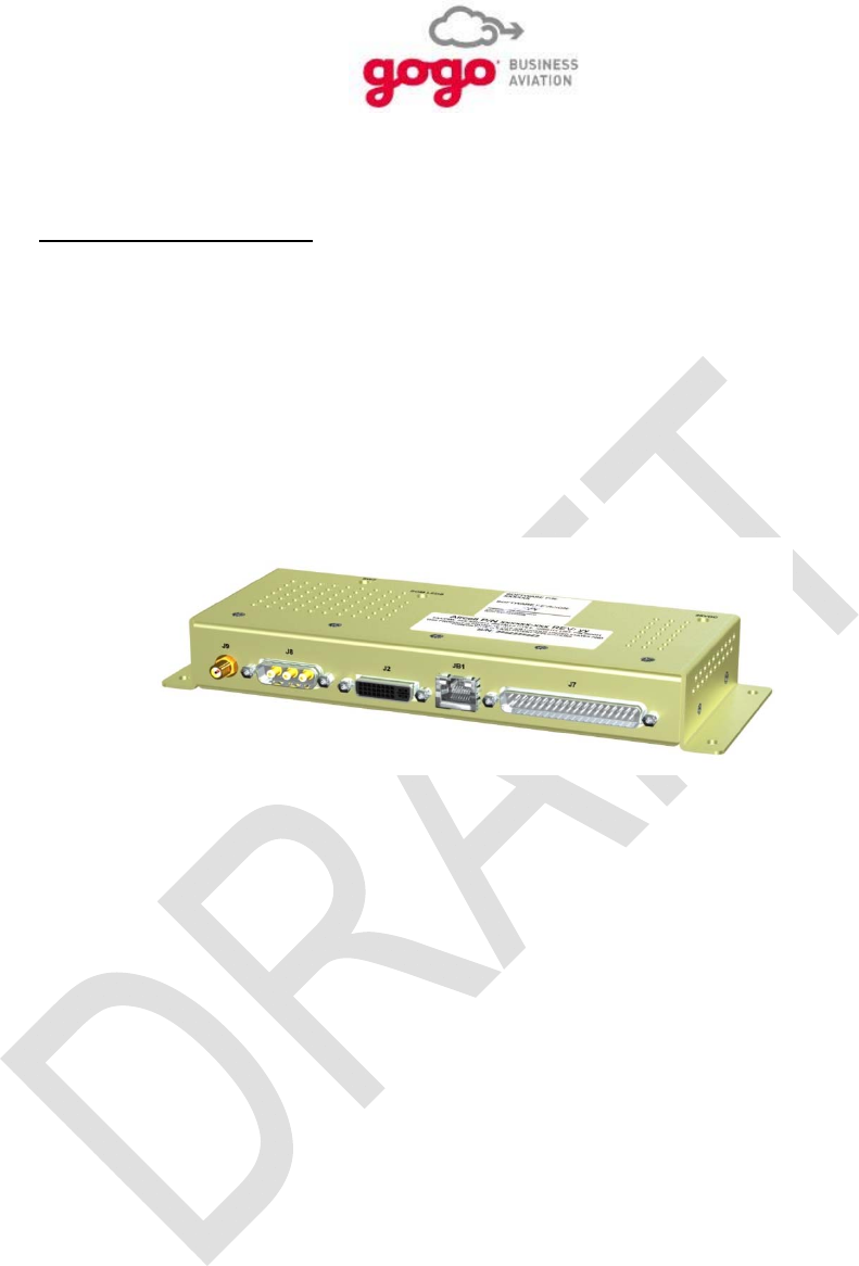
An installation comprises of the GVPU (P24486) LRU as seen in Figure 2.1.
Figure 2.1. GVPU
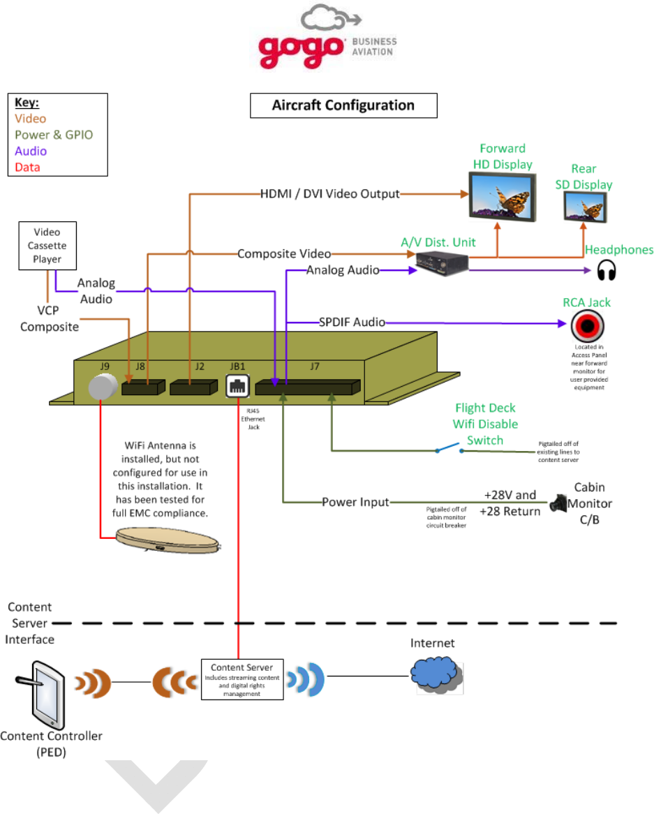
Figure 2.2 displays a diagram of the GVPU with an example of possible aircraft IFE configurations.
The GVPU receives power from the 28 volt aircraft bus via a dedicated circuit breaker or the cabin
monitor circuit breaker if this simplifies installation.
The GVPU outputs audio in S/PDIF format or analog format to the aircraft audio distribution system or
direct to the fixed cabin monitor depending on the aircraft configuration.
The video content is streamed from the UCS content server to the GVPU via a wired Ethernet port. The
GVPU outputs a composite video signal and/or an HDMI signal containing video data to the cabin monitor
based on user selection. The composite video signal exits via a D-sub connector. The HDMI link uses a
DVI-style connector which can be secured using the fixed jackscrews for use in a vibrating environment.
Description and Operation, Section 2 Page 2-2
Gogo Business Aviation confidential and proprietary D18340-A, May 2015
Figure 2.2. Sample GVPU Installation
The GVPU is mounted via holes in flanges at both ends of the enclosure.
The dimensions of the GVPU including mounting flanges are 3.23” W × 9.25” L × 1.33” H.
Description and Operation, Section 2 Page 2-3
Gogo Business Aviation confidential and proprietary D18340-A, May 2015
2.2. GVPU Indicators
The GVPU contains several internal LED indicators for power and general status. These are labeled on
the exterior of the GVPU and the location and function are shown on the Interface Control Drawing (ICD)
in Section 10 of this document.
2.3. GVPU Power
The GVPU must be installed within the aircraft pressure vessel. For an installation where the GVPU is
powered through a dedicated circuit breaker, a 1 Amp circuit breaker is recommended.
As the GVPU consumes very little power, installation may be simplified if the GVPU is powered by the
same circuit as the cabin monitor to which it will be connected. In this case, review the cabin monitor
power requirements and adjust the monitor circuit breaker size accordingly to accommodate the
incremental power draw of the GVPU.
2.4. Component Part Numbers
Description Manufacturer Part Number Quantity Applicability
GVPU Gogo Business
Aviation P24486 1 All
Table 2.1. GVPU Equipment Installed
2.5. General Purpose Input/Output
The GVPU contains a number of definable General Purpose Input/Output (GPIO) connections. At
present, only one GPIO1 N is used for a remote Wi-Fi disable capability when connected to a switch in
the cockpit or to the Wi-Fi disable function on the Gogo UCS system. The remaining ports are reserved
for future function expansion.
The GPIO ports are active low and each can handle 28 VDC at 50 mA.
2.6. Physical Characteristics
The GVPU has a mounted footprint 9.25” x 3.23”. The height is 1.33” from the mounting surface to the
top of the enclosure. Refer to the GVPU interface drawing D171130, in Section 6.0 for details.
The GVPU chassis is made of wrought aluminum alloy. An anodized finish is applied to all external
surfaces, providing the chassis with excellent corrosion resistance, while also making it electrically
nonconductive.
All of the electrical connections to the GVPU are on one side of the box which offers convenient access
for maintenance purposes. The GVPU must be installed in the pressurized cabin area or avionics bay.
Keep in mind the cable lengths and routing requirements. Depending on the placement of the unit, it may
be necessary and/or desirable to use right-angle connectors. Ensure that connectors do not interfere with
each other in the final selected configuration.

Description and Operation, Section 2 Page 2-4
Gogo Business Aviation confidential and proprietary D18340-A, May 2015
Refer to Section 7.4.1., GVPU System Specifications, for details regarding the environmental
requirements for this unit. The GVPU has low power requirements such that natural convection cooling
will be adequate for most mounting locations.

Installation Procedures, Section 3 Page 3-1
Gogo Business Aviation confidential and proprietary D18340-A, May 2015
3.0 INSTALLATION PROCEDURES
3.1. Planning
Careful planning will ensure an efficient installation of the GVPU with minimum down time for the aircraft
and will ensure optimal system performance and easy maintenance access in the future. Plan equipment
locations with service in mind, and select the proper cabling before ordering.
Refer to aircraft manufacturing guidelines and/or Advisory Circular 43.13-1B and 2B. Advisory Circular
43.13-1B (Acceptable Methods, Techniques, and Practices) Chapters 11 and 12, and Advisory Circular
43.13-2B (Acceptable Techniques, and Practices-Aircraft Alterations) Chapters 1 and 2, and SAE
AS83519 (Shield Termination, Solder Style, Insulate, Heat-Shrinkable, Environment Resistant, General
Specification For) and SAE ARP1870 (Aerospace Systems Electrical Bonding and Grounding for
Electromagnetic Compatibility) provide excellent guidelines to ensure a good installation.
A field-approved FAA Form 337, Supplemental Type Certificate (STC) or Type Certificate (TC) is the
usual required documentation path for the installation of this system.
3.2. Equipment Location
If this is a new installation of a GVPU, select cabling as specified in this manual to satisfy the approved
requirements of the system.
The GVPU must be located inside the pressure vessel. The LRU should be located near the cabin
monitor to which it will be connected to avoid long runs of HDMI cabling. The LRU can be mounted in
any orientation but be aware of any interference which may result between the electrical connectors and
surrounding cabling or aircraft structure. Refer to Section 7.0, System Specifications, for details
regarding the environmental requirements for this unit. Refer to Section 6.0 for mechanical installation
details.
3.3. Equipment Configuration
There are many variations in how the GVPU may be configured as part of the aircraft’s IFE system. The
configuration selected will be based on several factors which will include the customer’s requirements, the
type of cabin monitor(s) on the aircraft, the capabilities of the existing CMS and/or A/V Distribution
System, and how many existing audio/video resources are retained and need to be integrated with the
GVPU.

Installation Procedures, Section 3 Page 3-2
Gogo Business Aviation confidential and proprietary D18340-A, May 2015
3.3.1. Considerations Regarding Current System
Following is a list of questions to keep in mind when determining the optimal configuration for a specific
installation. They may be used as is or adapted to any particular situation based on the level of
complexity of the system.
Is there an A/V distribution System?
What type of Audio/Video Input does it have
Is there an available (unused) Audio/Video input.
Will the GVPU be connected directly to a monitor in the aircraft?
Is there more than one cabin monitor?
Is there an available HDMI or Composite input to the monitor?
How will audio from the monitor be distributed throughout the aircraft?
3.3.2. Sample Configurations
Following are some examples of possible installation configurations. These should only serve as
guidelines for actual installations as the final configuration will depend on numerous factors as described
above.
3.3.2.1. Single Digital Video Source
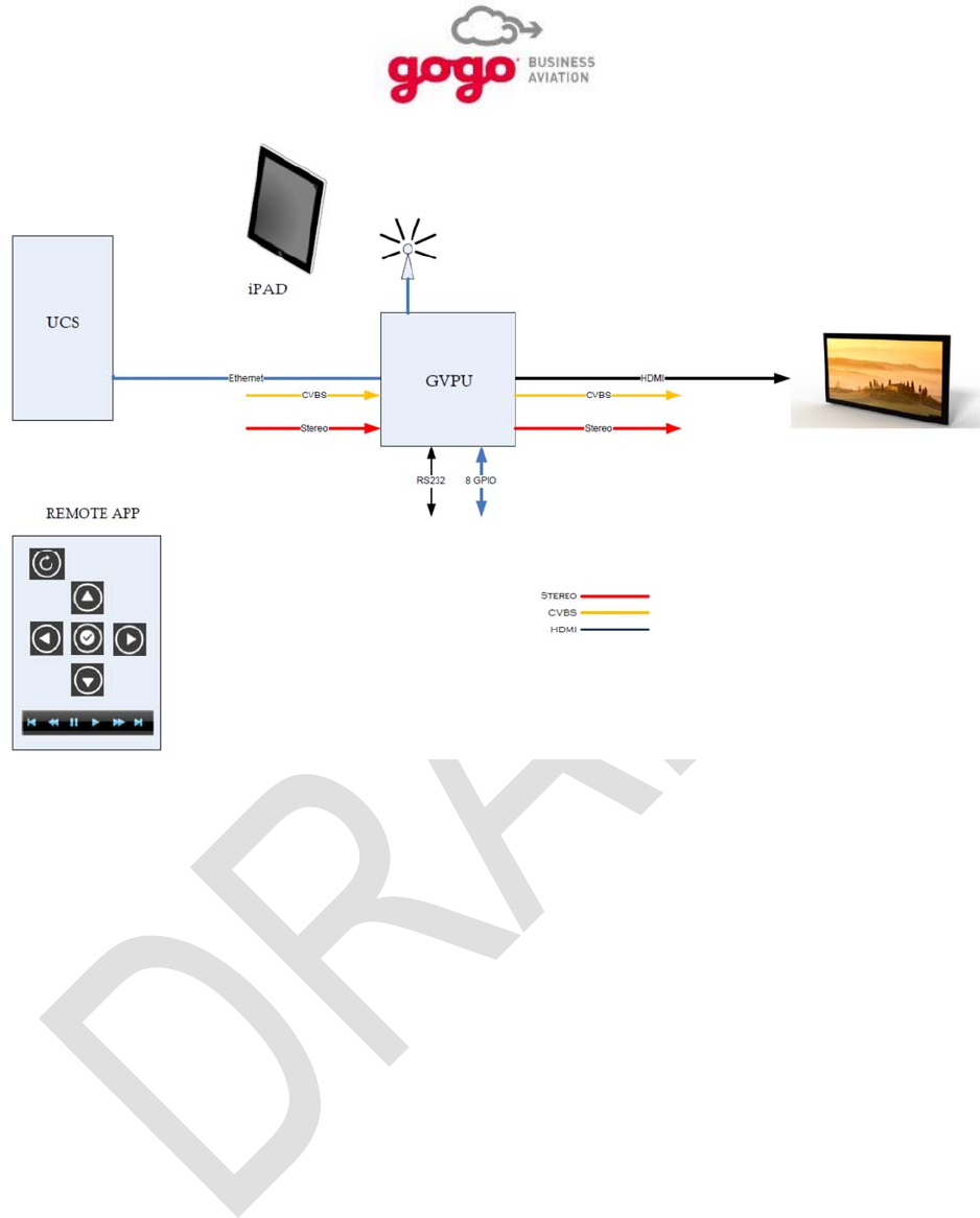
For an aircraft installation with no A/V distribution system, the GVPU will be installed directly to a cabin
monitor. Figure 3.1 shows a block diagram of this installation.
Installation Procedures, Section 3 Page 3-3
Gogo Business Aviation confidential and proprietary D18340-A, May 2015
Figure 3.1. Single Digital Video Source
3.3.2.2. GVPU as an Input Source to the CMS/A/V Distribution System
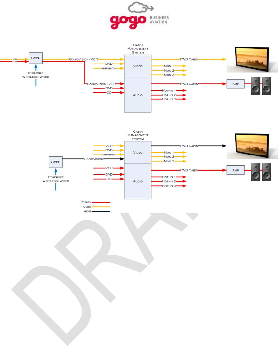
Many aircraft will have an existing CMS or A/V distribution system with a variety of audio and video
sources. In this case, the GVPU can be integrated to serve as an additional input to the existing system.
Figure 3.2 shows some examples of this configuration. Some aspects to consider when the GVPU is
integrated as in input source to the CMS or A/V distribution system:
If an aircraft is equipped with more than one cabin monitor and each is intended to display
individually controlled video, then more than one GVPU will need to be installed as input to the
CMS or A/V distribution system. In this case (more than one GVPU installed), each GVPU will
require a uniquely configured Internet Protocol (IP) address
If more than one GVPU is installed, each GVPU will need to be configured with a unique IP
address. See section 2.5 – General Purpose Input/Output for setting the IP address.
Installation Procedures, Section 3 Page 3-4
Gogo Business Aviation confidential and proprietary D18340-A, May 2015
Figure 3.2. Multiple Video Sources, GVPU Before CMS
3.3.2.3. Multiple Video Sources; GVPU after CMS
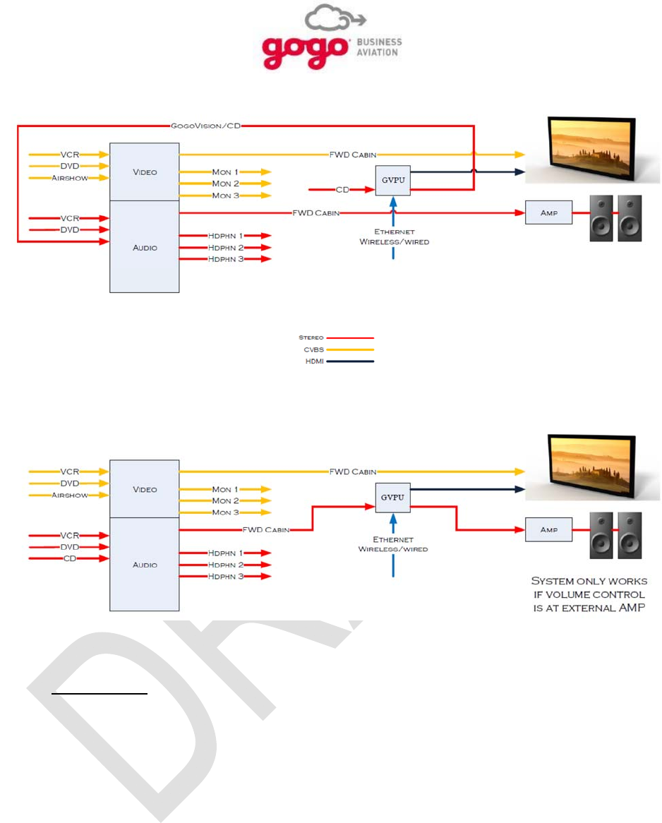
An alternative is to integrate the GVPU downstream or after the existing/upgraded CMS. This
configuration may be desirable if an HD capable cabin monitor is to be added solely to accommodate
digital video from the Gogo UCS system or other digital video content server. An additional application
provides the addition of HD video without changing the composite video source configuration and
connection to the CMS. Figure 3.3 shows some examples of this configuration.
Some aspects to consider when the GVPU is integrated after the CMS are:
Audio associated with HD video will only be available on cabin speakers unless the audio is
routed back into the CMS.
Audio volume control will be necessary at the amplifier unless audio is routed back into the CMS.
Installation Procedures, Section 3 Page 3-5
Gogo Business Aviation confidential and proprietary D18340-A, May 2015
Figure 3.3. Multiple Video Sources, GVPU After CMS
3.4. Cable Routing
Draw a cable routing diagram for the aircraft. Refer to Wiring Instructions in Section 10.0 to determine the
required cables, then measure and record the required cable lengths on a worksheet. Allow for adequate
bend radius, service loops, and stress relief in all cable routes.

Installation Procedures, Section 3 Page 3-6
Gogo Business Aviation confidential and proprietary D18340-A, May 2015
3.5. Cabling
The GVPU electrical connections are denoted as connectors JB1, J2, J7, J8, and J9. Detailed pin-outs
and connector part numbers are shown in the ICD, drawing D17113 in Section 10.0
Connector JB1 is a standard RJ-45 Ethernet jack to enable an Ethernet connection to the device. Refer
to Gogo drawing D17113 in Section 10.0.
Connector J2 is a Digital Video Interface (DVI) connector and provides the HDMI audio/video output.
Refer to Gogo drawing D17113 in Section 10.0.
Connector J7 is a 37-pin d-sub connector and provides for DC power input, analog audio input and
output, digital audio output, a USB connection (factory use only), two RS-232 ports (factory use only), and
all GPIO connections. Refer to Gogo drawing D17113 in Section 10.0.
Connector J8 has a d-sub-style shell with three coaxial ports for composite video input, composite video
output, and switched composite video output. Refer to Gogo drawing D17113 in Section 10.0.
Connector J9 is an SMA jack that has no use at this time. Refer to Gogo drawing D17113 in Section
10.0.
RF Transmission Characteristics, Wi-Fi
Operating Frequency Range...... 2.412 to 2.462 GHz
Transmit Power ………………… Less than 0.1 W max (less than 100 mW)
Per 802.11 b/g/n Wireless Broadband Router FCC Part 15 regulations
NOTE
Wire and Cable Installation
Wire installation should be done according to approved aircraft manufacturing guidelines and/or
FAA procedures documented in Advisory Circular 43.13-1B. Consider cable slack, protection
from heat, and protection from chafing when installing system wiring.
Good installation practices will ensure maximum performance for the GVPU. Advisory Circular 43.13-2B
(Acceptable Techniques, and Practices - Aircraft Alterations), Chapter 1 and 2, Advisory Circular 43.13-
1B (Acceptable Methods, Techniques, and Practices), Chapter 11, SAE AS83519 (Shield Termination,
Solder Style, Insulate, Heat-Shrinkable, Environment Resistant, General Specification For) and SAE
ARP1870 (Aerospace Systems Electrical Bonding and Grounding for Electromagnetic Compatibility)
provide excellent guidelines to ensure a good installation. When building the system wire harness,
observe the following:

Installation Procedures, Section 3 Page 3-7
Gogo Business Aviation confidential and proprietary D18340-A, May 2015
1. Plan the GVPU cable routing so that it does not interfere with flight control cables or follow heavy
current-carrying cables, hydraulic lines, or fuel lines.
2. It is essential to use military specification connectors or connectors approved for use on aircraft.
3. This document, attached ICD and attached wiring instructions only show a suggested circuit
breaker size, wire size & type for a typical installation:
It is the responsibility of the installation agency to ensure proper wire type and size and the
use of a properly rated circuit protection device (circuit breaker). In addition, ensure that the
28 VDC equipment bus is connected so it can handle the additional electrical load.
Install circuit protection (circuit breaker) of the proper amperage to handle the power
requirements and protect the wiring.
Refer to aircraft manufacturing guidelines and/or refer to FAA Advisory Circular 43.13-1B,
Section 11 (Aircraft Electrical Systems) for the proper wire types and circuit protection
recommendations. All wiring and coax cabling shall conform to the flammability requirements
of FAR 25.869.
Single wire conductors shall conform to aircraft manufacturing guidelines and/or the
specification for Wire, Electrical, Fluoropolymer-Insulated, and Society of Automotive
Engineers (SAE)-AS22759, also known as Military (MIL)-W-22759.
Shielded wire conductors shall conform to Aircraft manufacturing guidelines and/or the
Standard for Aerospace and Industrial Electrical Cable, National Electrical Manufacturers
Association (NEMA) WC 27500, also known as MIL-DTL-27500.
Size power wires and circuit protection to handle an operational voltage range 18.0 - 33.2
VDC with a nominal power draw of 7.6 watts @ 28 VDC and a maximum power draw of 14.0
watts @ 28 VDC.
The Wiring Diagrams in Section 10.0 provide manufacturing instructions for the wire harnesses. Notes on
the wiring diagrams provide essential instructions that will save you needless rework during installation.
NOTES
Component Bonding
As with any communication equipment, bonding the equipment to the airframe ground is essential
for optimum performance, compliance, and lightning protection. Ensure that the equipment
mounting provisions (tray or bulkhead mounting rails) are bonded to the shelf, and the shelf is
bonded to airframe ground. Properly bonded, there should be 2.5 milliohms or less between the
mounting tray and airframe ground. Care in bonding has been shown to eliminate erratic or poor
system performance.
Additional Shield Drain Information
As an option, up to four 22 American Wire Gauge (AWG) 7” drains may be combined on a single
grounding strap and then routed to airframe chassis. The ground strap should be as short as
possible, but may be realized with a maximum of 24” of insulated (18 AWG or larger).
4. To reduce EMI/RFI to an acceptable level, signal lines may require shielded cables. Refer to the
wiring instructions in Section 10.0.

Installation Procedures, Section 3 Page 3-8
Gogo Business Aviation confidential and proprietary D18340-A, May 2015
3.6. Antenna Mounting
The Wi-Fi antenna, used when the connection between the content server (UCS or other) is Wi-Fi instead
of hardwired Ethernet, must be installed such that 20 cm is maintained between the antenna and the
users under normal circumstances.
For optimal Wi-Fi performance, the Wi-Fi antenna should be mounted on a non-metallic surface and/or
secured with cable ties. The Wi-Fi antenna can be mounted to a metallic surface, but should have direct
line of sight (LOS) to the cabin in such a situation.
The Wi-Fi antenna is omni-directional but it is recommended to be mounted with the radome facing the
target area.
3.7. Remote Ground Maintenance Ethernet
Normally, the GVPU will be utilized in conjunction with the Gogo UCS system to display video content on
a cabin monitor or monitors. In this case, Ethernet access to the GVPU for configuration purposes can be
made through the aircraft network used by all the UCS system components. The UCS may be connected
through a Wi-Fi connection or the physical Ethernet jack on the GVPU. Instances where the GVPU is
installed in a location that is not easily accessible, and the Ethernet jack is not used for connecting to the
UCS system or other content server, it is recommended that the Ethernet port be wired to an easily
accessible bulkhead-mounted or panel-mounted RJ-45 connector. This will provide a hardwired Ethernet
connection to the GVPU for configuration and diagnostic purposes regardless of the status of the Wi-Fi
connection.

Setup, Configuration, and Functional Testing, Section 4 Page 4-1
Gogo Business Aviation confidential and proprietary D18340-A, May 2015
4.0 SETUP, CONFIGURATION, and FUNCTIONAL TESTING
NOTE
READ THIS ENTIRE SECTION BEFORE PERFORMING ANY SETUP OR TESTING ON THE GOGO
BUSINESS AVIATION EQUIPMENT!
Proper setup is an absolute requirement for the GVPU to function properly in the IFE system. DO
NOT fly the aircraft unless all the steps have been completed correctly and verified.
4.1. Introduction
When the installation is complete and you have complied with the wiring and cabling requirements of this
Manual (D18340), perform a final check of the Direct Current (DC) power input connections to the GVPU.
Verify that ground and 28 VDC connections to the unit are correct and on the proper pin numbers. This
will ensure confidence when you apply power to the unit for the first time. After verifying that the DC
power inputs are on the proper power pins, pull open the circuit breaker and connect the power cable to
the GVPU. Close the circuit breaker.
CAUTION
Before disconnecting or reconnecting the GVPU, pull open the power circuit breaker to avoid damage to
the GVPU or the aircraft wiring.
4.2. Test Results
Documentation of the test results is important for the aircraft owner. All paperwork, provisioning, special
drawings, cable routings, and special installation procedures should be included for the aircraft records.
4.3. Control and Operation
If there are any questions on this process please contact Gogo Business Aviation Customer Service at
1.888.286.9876.
4.4. GVPU Configuration
The GVPU is a configurable device which provides for customization to meet end customers’ specific
needs and desires. The following instruction will serve as a guideline to configure a GVPU installation
based on how the GVPU is integrated into the aircraft IFE system.
4.4.1. GVPU Address Scheme
Refer to Table 4.1. for recommended GVPU IP assignments.
NOTE
Installers must take into consideration their particular IP address configuration when installing the GVPU
with Networked Integrated Cabin Equipment (NICE).

Setup, Configuration, and Functional Testing, Section 4 Page 4-2
Gogo Business Aviation confidential and proprietary D18340-A, May 2015
Reference GPIO IP Address Mapping
GVPU IP ADDRESS PIN 29 (GPIO 2) PIN 10 (GPIO 3)
172.20.10.10 (DEFAULT) FLOATING FLOATING
172.20.10.11 GROUNDED FLOATING
172.20.10.12 FLOATING GROUNDED
172.20.10.13 GROUNDED GROUNDED
Table 4.1. Reference GPIO IP Address Mapping
4.4.2. Accessing the GVPU Configuration Page
To access the GVPU configuration page, connect a computer to the Ethernet network associated with the
GVPU. This will typically be the primary aircraft data communications network to which the Gogo UCS
system or other content server is connected.
If the connection between the GVPU and content server is via Wi-Fi and the Ethernet port on the GVPU
(or its remote equivalent) is available, connect the computer here. In this case, it will be necessary to
manually set an IP address on the computer as the GVPU does not have the ability to provide one. Use
the following steps to prepare the computer:
1. Access the laptop’s Control Panel and select Network and Sharing Center.
2. From the menu on the left side of the window, click on Change Adapter Settings.
3. Right click on the laptop’s Local Area Connection (names may vary) and then click Properties
in the subsequent drop-down menu.
4. In the center table of the new window, click on Internet Protocol Version 4 (TCP/IPv4) and then
click Properties when it is highlighted.
5. If it’s not already highlighted, click the Use the following IP address: radio button. Enter the
following IP addresses then click OK:
a. IP address: 172.20.10.XX, where XX is between 11 and 99.
b. Subnet mask: 255.255.255.0
c. Default gateway: 172.20.10.2
Once connected, open a browser on the computer and navigate to the following IP address:
172.20.10.10
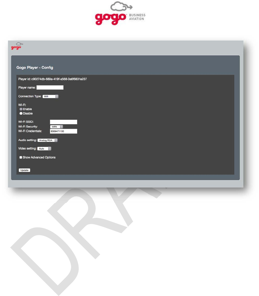
This will access the GVPU Configuration page which is shown in Figure 4.1.
Setup, Configuration, and Functional Testing, Section 4 Page 4-3
Gogo Business Aviation confidential and proprietary D18340-A, May 2015
Figure 4.1. GVPU Configuration Page
Setup, Configuration, and Functional Testing, Section 4 Page 4-4
Gogo Business Aviation confidential and proprietary D18340-A, May 2015
4.4.2.1. GVPU Configuration
The configuration elements of the GVPU shown on the Configuration pages are described below:
4.4.2.2. Player ID:
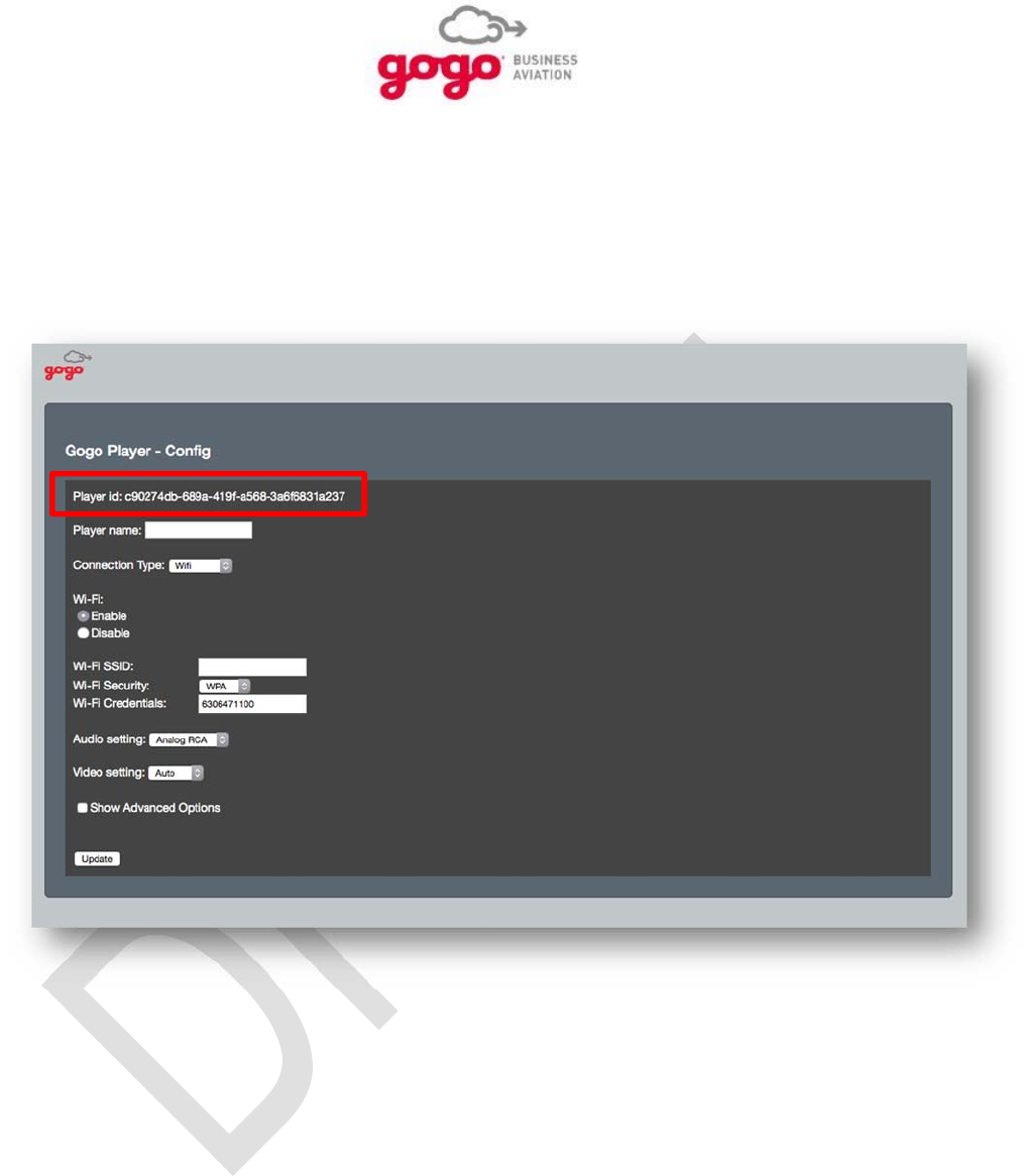
The Player ID is automatically populated and should not be changed. This value is available for
diagnostic purposes only.
Figure 4.4. Player ID
Setup, Configuration, and Functional Testing, Section 4 Page 4-5
Gogo Business Aviation confidential and proprietary D18340-A, May 2015
4.4.2.3. Player Name:
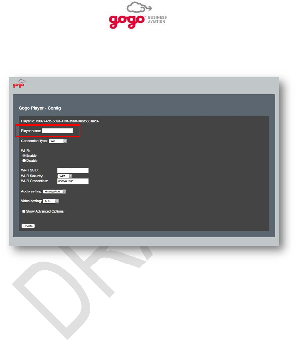
Select the Player Name based on customer or operator preference. There are no limitations in regards to
format. If more than one GVPU are installed on the same aircraft, choose unique names for each GVPU.
Figure 4.5. Player Name
Setup, Configuration, and Functional Testing, Section 4 Page 4-6
Gogo Business Aviation confidential and proprietary D18340-A, May 2015
4.4.2.4. Connection Type:
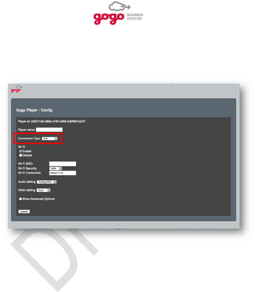
Connection type refers to the connection between the GVPU and the video content server, typically the
Gogo UCS system. Set Ethernet when a hardwired Ethernet connection is used. This is the preferable
connection type if the installation allows. Set Wi-Fi when a wireless connection is used because a
hardwired Ethernet connection is not possible or desired. For a Wi-Fi connection, additional required
configuration parameters are described below.
Figure 4.6. Connection Type
Setup, Configuration, and Functional Testing, Section 4 Page 4-7
Gogo Business Aviation confidential and proprietary D18340-A, May 2015
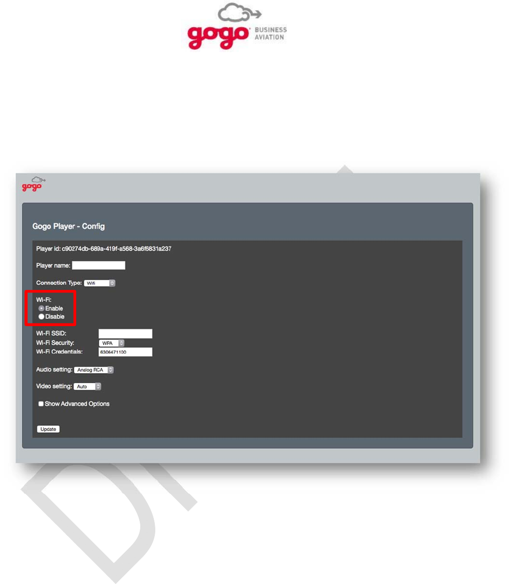
4.4.2.5. Wi-Fi: Enable/Disable
The Wi-Fi parameter provides two radio buttons:
- Select Enable when the connection between the GVPU and video content server is Wi-Fi.
- Select Disable when the connection between the GVPU and video content server is hardwired
Ethernet. Also use this selection for specific diagnostic purposes even when the connection is
Wi-Fi.
Figure 4.7. Wi-Fi: Enable/Disable
Setup, Configuration, and Functional Testing, Section 4 Page 4-8
Gogo Business Aviation confidential and proprietary D18340-A, May 2015
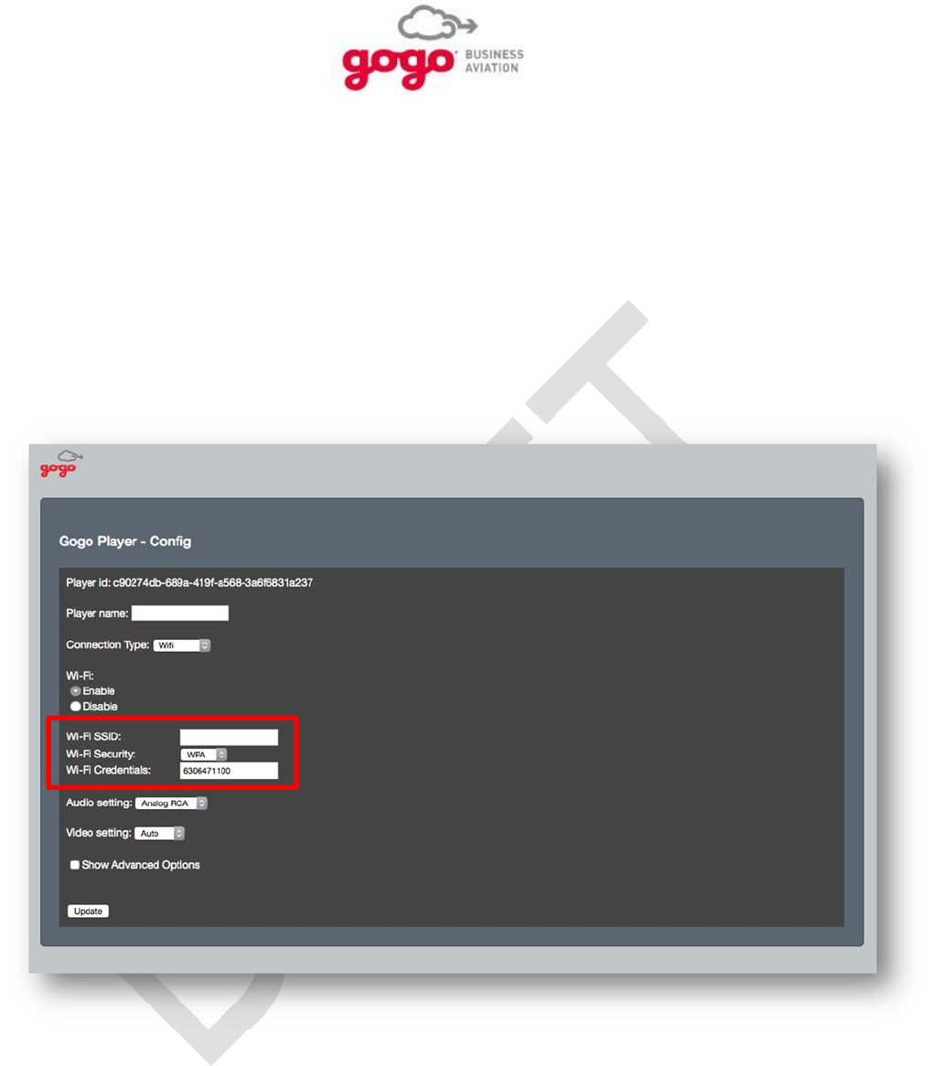
4.4.2.6. Wi-Fi SSID:
The Wi-Fi SSID is only necessary when the connection between the GVPU and video content server is
wireless. This will typically be the SSID of the wireless access point (WAP) of the Gogo UCS system
when installed. If an alternate content server is installed, use the SSID from this source.
4.4.2.7. Wi-Fi Security:
Set this parameter to match the security parameters of the video content server when the connection to
the GVPU is Wi-Fi.
4.4.2.8. Wi-Fi Credentials:
Set this parameter to match the security parameters of the video content server when the connection to
the GVPU is Wi-Fi.
Figure 4.8. Wi-Fi SSID/ Security/ Credentials
Setup, Configuration, and Functional Testing, Section 4 Page 4-9
Gogo Business Aviation confidential and proprietary D18340-A, May 2015
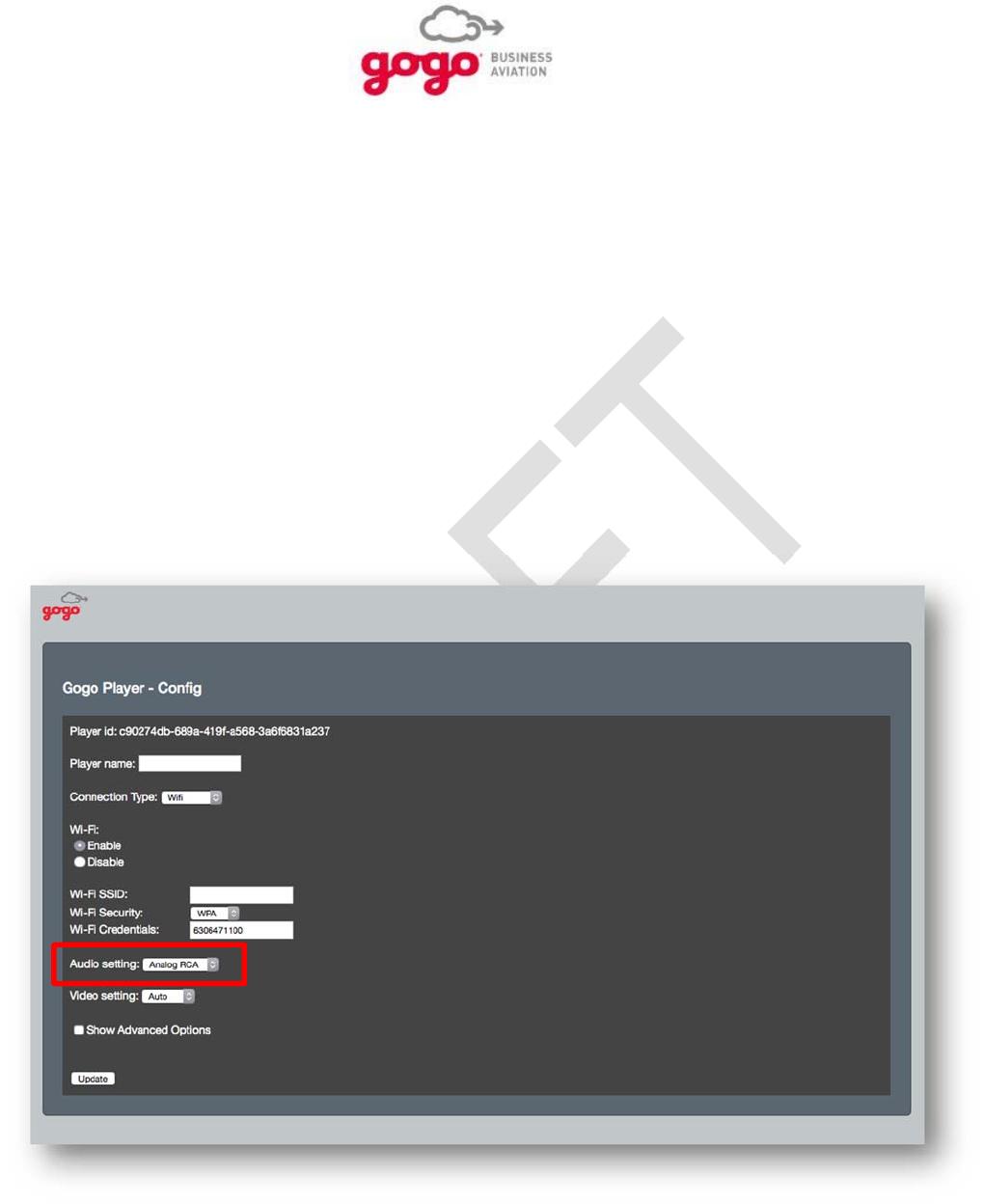
4.4.2.9. Audio Setting:
The Audio Setting parameter determines the audio output format of the audio signal associated with
digital input.
Set this parameter to S/PDIF when a digital audio signal associated with the digital input is to be
made available on the S/PDIF connections. Use the capability when the A/V Distribution system
on the aircraft is capable of accommodating digital audio. When set to S/PDIF, any analog audio
signal connected to the analog audio input connection will not be available on the analog audio
output connection. Any analog audio signal connected to the analog audio input connection will
only be available on the switched analog audio output connection when there is no digital audio
as a result of no digital video input.
Set the parameter to Analog RCA when any audio source is to be connected to a CMS or A/V
distribution system only capable of accommodating analog audio signals. When set to Analog
RCA, the audio input associated with a digital video input signal will be available on the switched
analog audio output connection in analog format. Any analog audio signal connected to the
analog audio input connection will only be available on the switched analog audio output
connection when there is no digital audio as a result of no digital video input.
Figure 4.9. Audio Setting
Setup, Configuration, and Functional Testing, Section 4 Page 4-10
Gogo Business Aviation confidential and proprietary D18340-A, May 2015
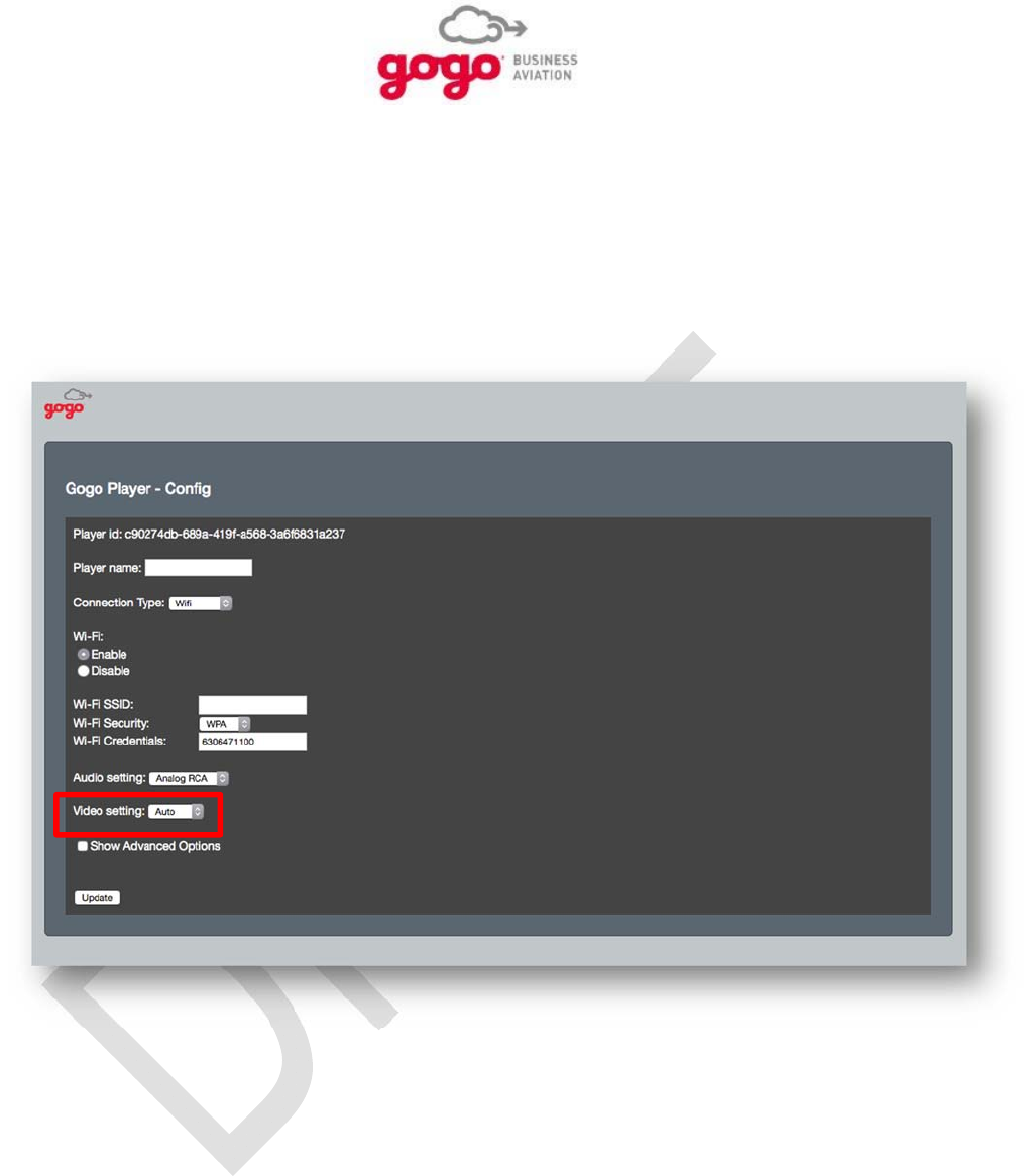
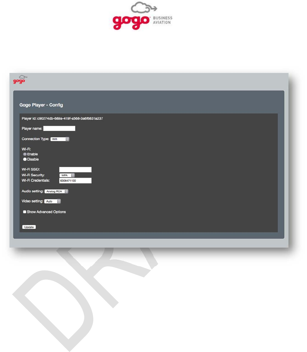
4.4.2.10. Video Setting:
The Video Setting parameter determines the video output format associated with a digital input signal.
Select 1080P for maximum HD image resolution when the connected cabin monitor or CMS can
accommodate this format.
Select 720P when the connected cabin monitor or CMS can only accommodate this format.
Select CVBS when the desired video output is composite format as required by the cabin monitor
or CMS.
Figure 4.10. Video Setting
Setup, Configuration, and Functional Testing, Section 4 Page 4-11
Gogo Business Aviation confidential and proprietary D18340-A, May 2015
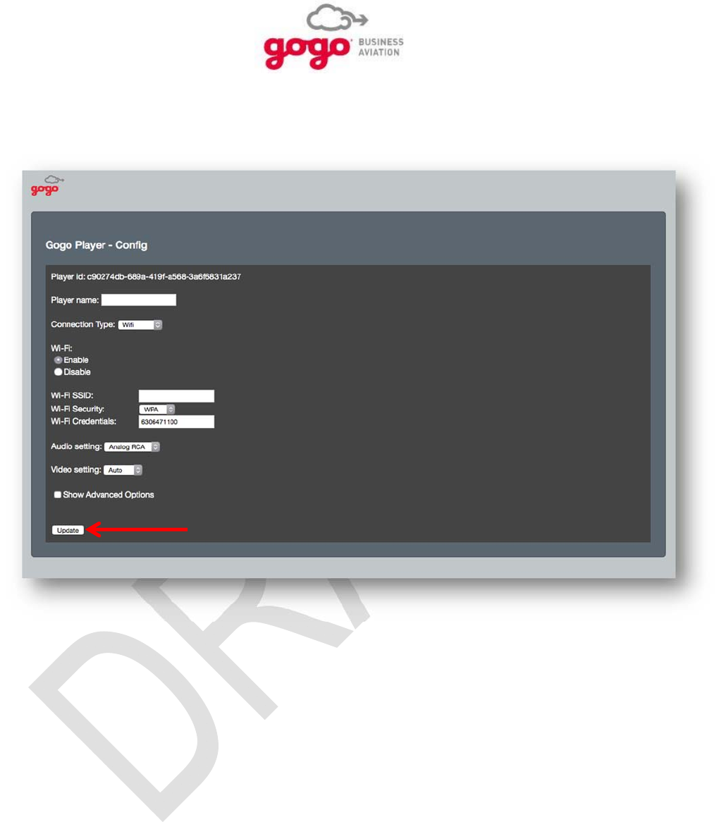
4.4.2.11. Show Advanced Options
Select the Show Advanced Options checkbox to access additional setup parameters.
Figure 4.11. Show Advanced Options
Setup, Configuration, and Functional Testing, Section 4 Page 4-12
Gogo Business Aviation confidential and proprietary D18340-A, May 2015
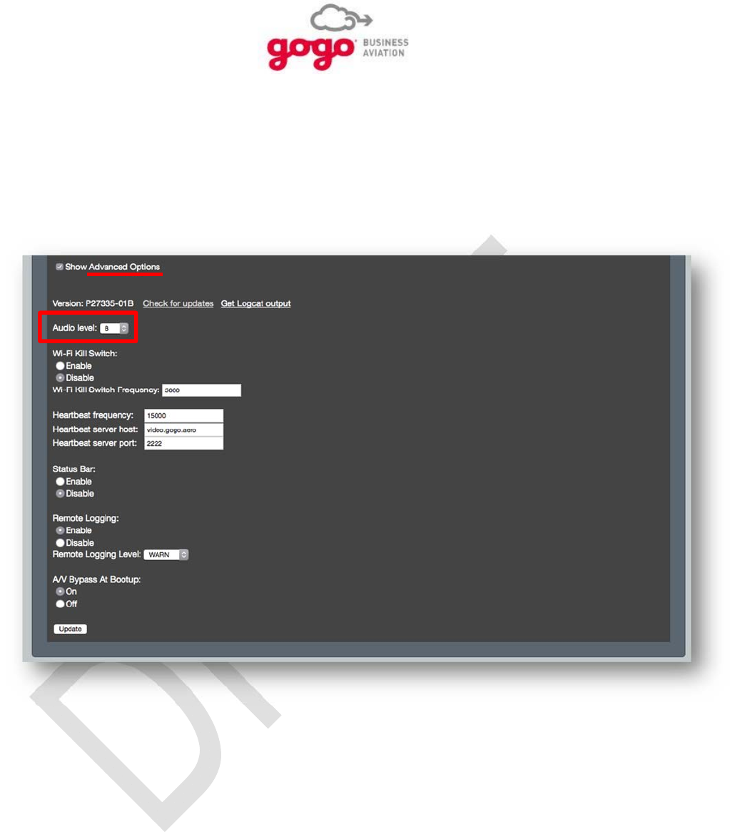
4.4.2.12. Update
Press update to save changes.
Figure 4.12. Update
Setup, Configuration, and Functional Testing, Section 4 Page 4-13
Gogo Business Aviation confidential and proprietary D18340-A, May 2015
4.4.3. GVPU Configuration – Advanced Options
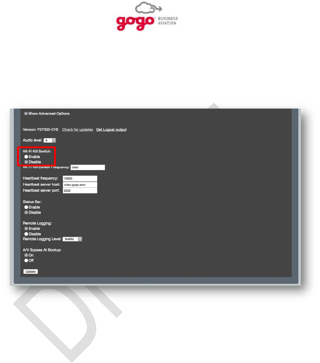
4.4.3.1. Audio Level:
This parameter is the volume control for the GVPU but should only be used to fix an audio level to any
device connected to the audio outputs. Actual audio levels as experienced by users of the system are to
be set by other means such as remote controls. The range of settings is 1 to 16. Set the audio level to 8
for most applications. Adjust this level up or down during system checkout as required.
Figure 4.13. Audio Level
Setup, Configuration, and Functional Testing, Section 4 Page 4-14
Gogo Business Aviation confidential and proprietary D18340-A, May 2015
4.4.3.2. Wi-Fi Kill Switch:
The Wi-Fi Kill Switch parameter provides two radio buttons:
Select Enable to allow proper functioning of the Wi-Fi kill switch wired to GPIO 1 or wired as part
of a UCS installation.
Select Disable to prevent any function of the Wi-Fi kill switch. Also select Disable when no Wi-Fi
kill switch is incorporated into the system.
Figure 4.14. Wi-Fi Kill Switch
Setup, Configuration, and Functional Testing, Section 4 Page 4-15
Gogo Business Aviation confidential and proprietary D18340-A, May 2015
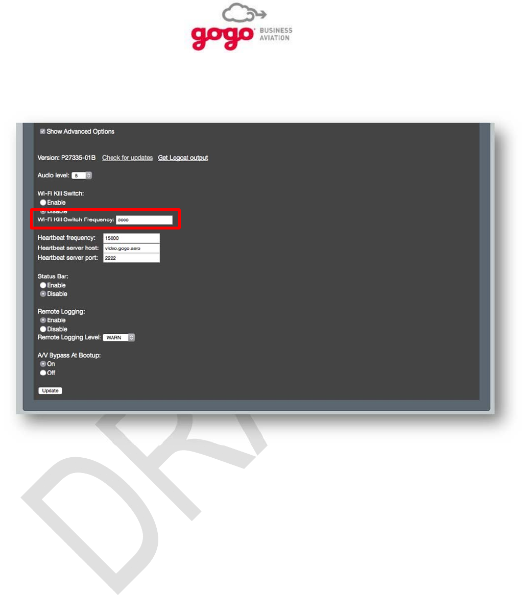
4.4.3.3. Wi-Fi Kill Switch Frequency:
Do not change this setting as it is intended for factory diagnostic purposes only
Figure 4.15. Wi-Fi Kill Switch Frequency
Setup, Configuration, and Functional Testing, Section 4 Page 4-16
Gogo Business Aviation confidential and proprietary D18340-A, May 2015
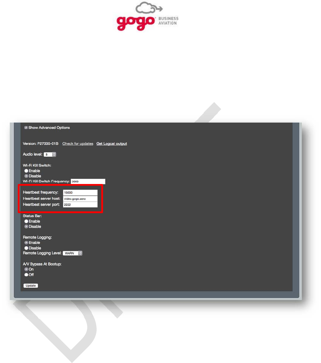
4.4.3.4. Heartbeat Frequency:
Do not change this setting as it is intended for factory diagnostic purposes only.
4.4.3.5. Heartbeat Server Host:
Do not change this setting as it is intended for factory diagnostic purposes only.
4.4.3.6. Heartbeat Server Port:
Do not change this setting as it is intended for factory diagnostic purposes only.
Figure 4.16. Heartbeat Frequency/Host/Port
Setup, Configuration, and Functional Testing, Section 4 Page 4-17
Gogo Business Aviation confidential and proprietary D18340-A, May 2015
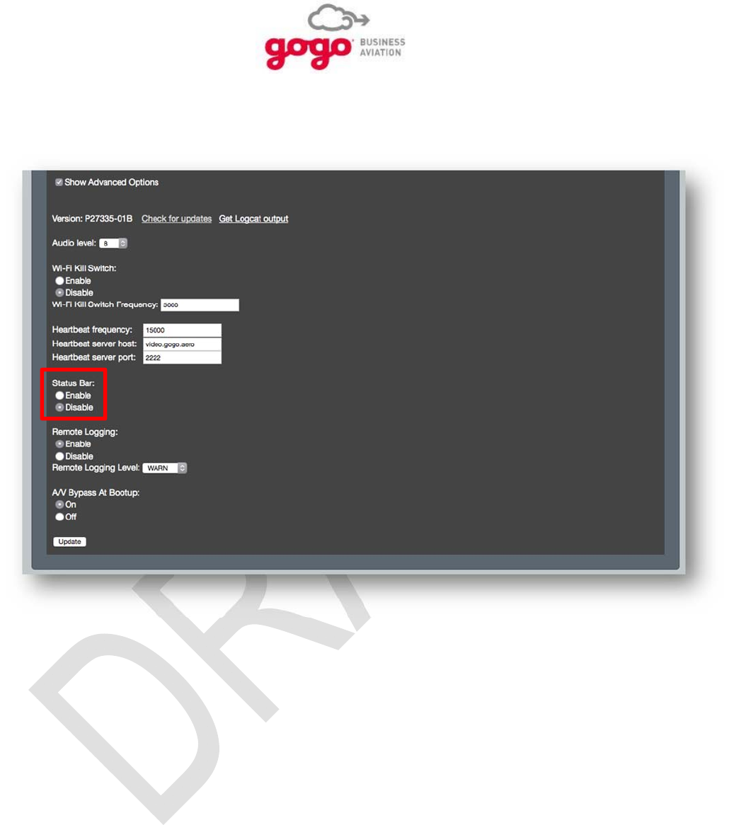
4.4.3.7. Status Bar:
Do not change this setting as it is intended for factory diagnostic purposes only.
Figure 4.17. Status Bar
Setup, Configuration, and Functional Testing, Section 4 Page 4-18
Gogo Business Aviation confidential and proprietary D18340-A, May 2015
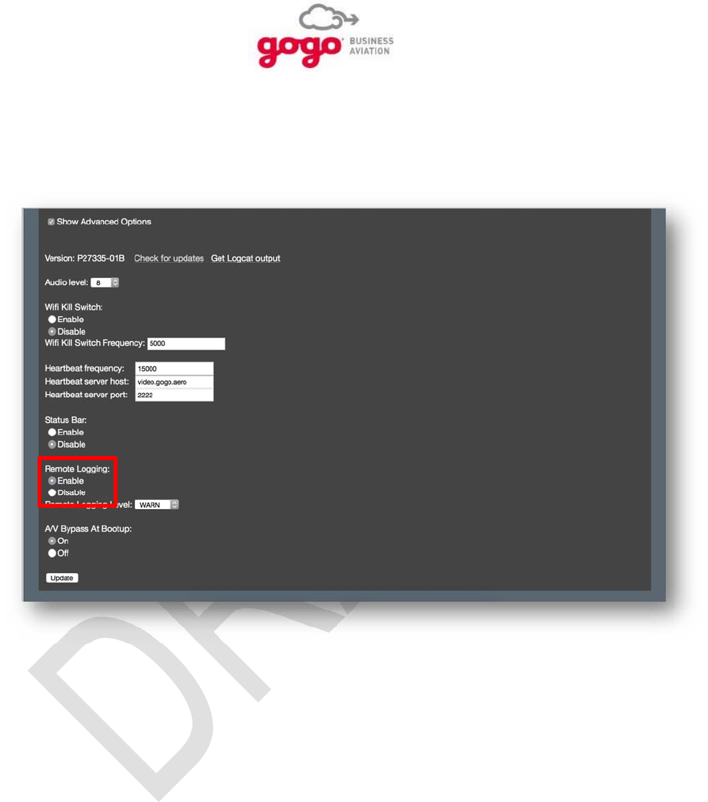
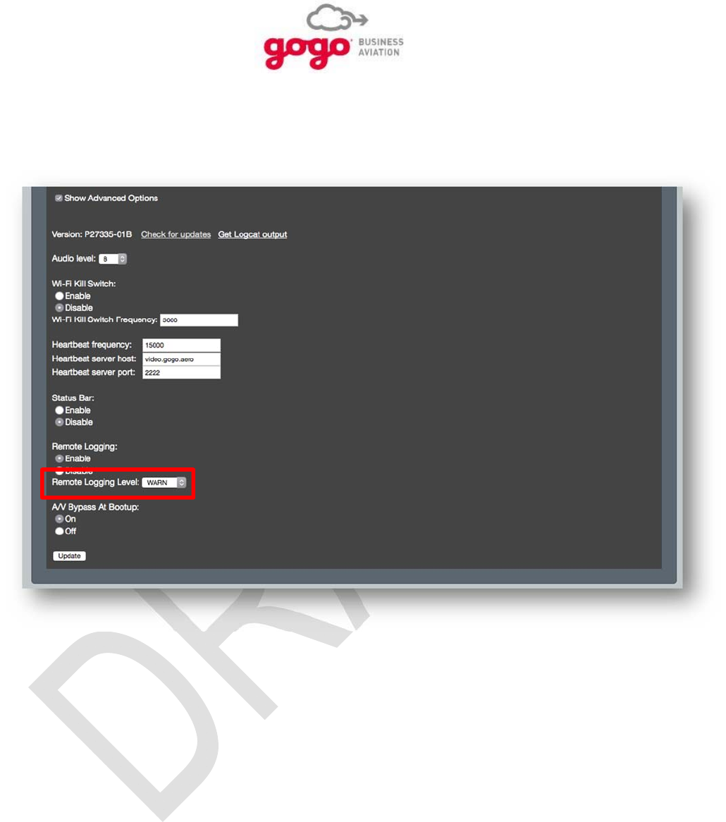
4.4.3.8. Remote Logging:
The Remote Logging at Bootup parameter provides two radio buttons:
Select Enable to allow GVPU messages to be logged to the Vision/UCS server.
Select Disable to prevent GVPU messages from being logged to the Vision/UCS server.
Figure 4.18. Remote Logging
Setup, Configuration, and Functional Testing, Section 4 Page 4-19
Gogo Business Aviation confidential and proprietary D18340-A, May 2015
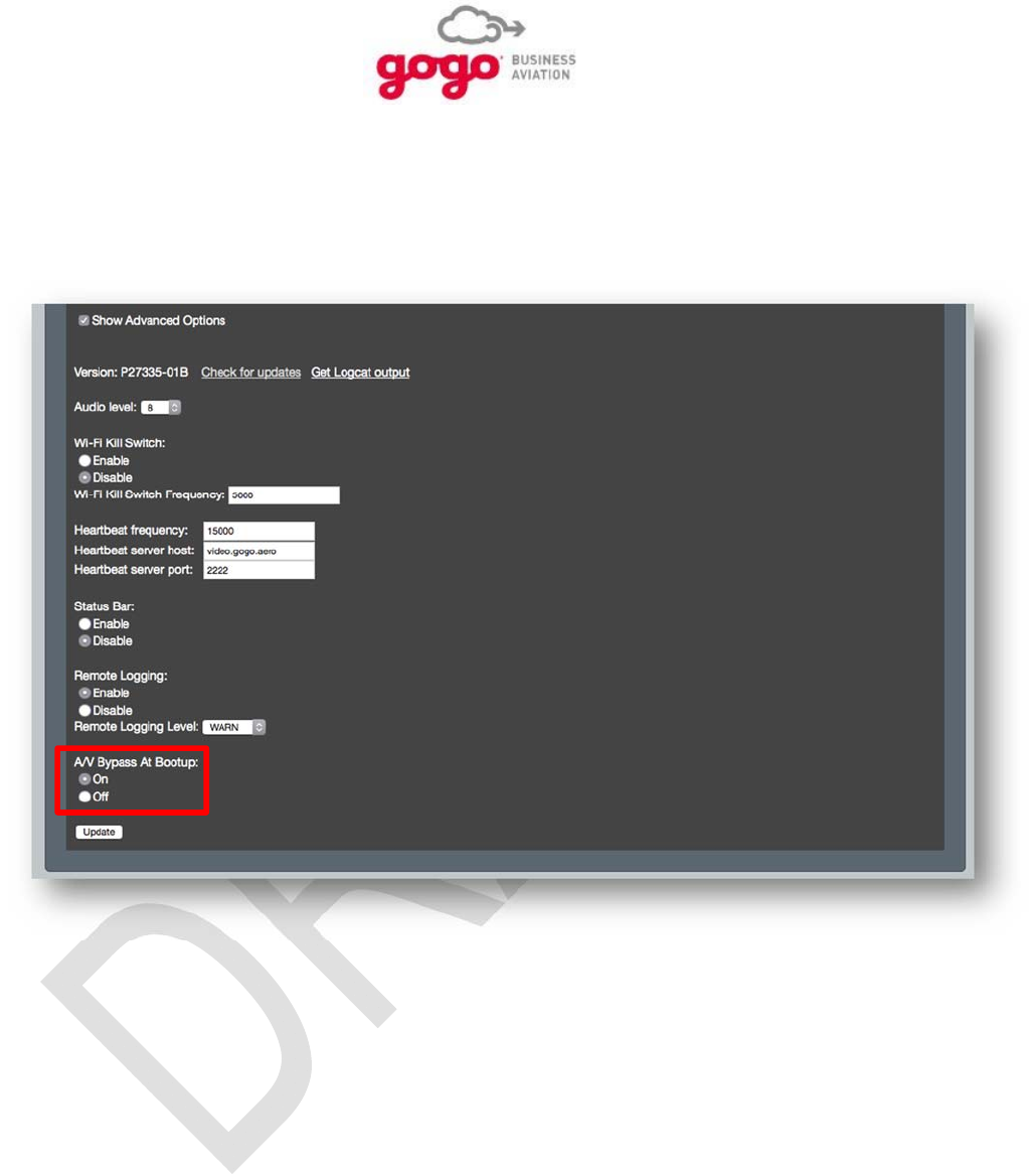
4.4.3.9. Remote Logging Level:
Because Remote Logging creates extra network traffic, this level should be set to the highest level
consistent with system functionality.
Figure 4.19. Remote Logging Level
Setup, Configuration, and Functional Testing, Section 4 Page 4-20
Gogo Business Aviation confidential and proprietary D18340-A, May 2015
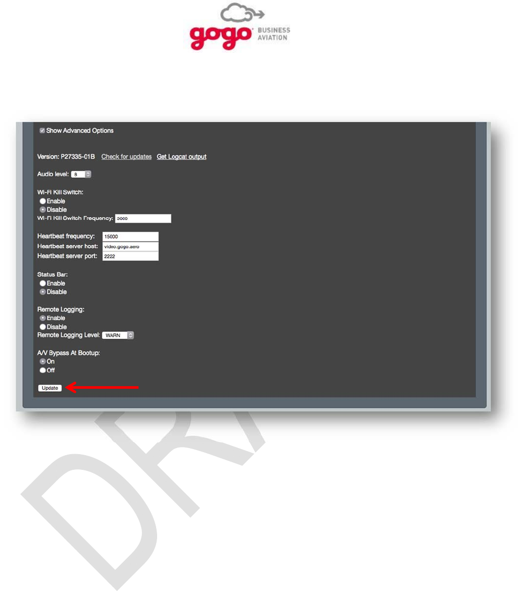
4.4.3.10. A/V Bypass at Bootup:
The A/V Bypass at Bootup parameter provides two radio buttons:
Select On to allow A/V to be turned on at bootup.
Select Off to prevent A/V to be turned on at bootup.
Figure 4.20. A/V Bypass at Bootup
Setup, Configuration, and Functional Testing, Section 4 Page 4-21
Gogo Business Aviation confidential and proprietary D18340-A, May 2015
4.4.3.11. Update
Press update to save changes.
Figure 4.21. Update

Setup, Configuration, and Functional Testing, Section 4 Page 4-22
Gogo Business Aviation confidential and proprietary D18340-A, May 2015
4.5. Functional Testing
4.5.1. System Operational Checks
GVPU operation is dependent on system configuration. It is necessary to know the following parameters
as they apply to the specific system being checked:
1. Monitor input: composite video or HDMI.
2. Video source(s): content server and/or composite video source.
3. Video input connection: hardwired Ethernet or Wi-Fi.
4. Audio source(s): content server for movies and/or other analog audio source.
5. Audio output: Analog RCA or S/PDIF.
6. IP address of the GVPU.
4.5.2. Required System Components
1. Known good monitor.
2. Known audio connection if installed.
3. Functional content server.
4. Functional external Internet connection to the content server for the DRM function.
5. Connected composite video source if installed.
6. Laptop computer (Windows 7 or higher and any Internet browser).
4.5.3. Operational Check: Configuration
1. Turn on power to the GVPU by closing applicable cabin monitor circuit breaker(s). Allow the
system to boot up. Boot-up will be complete when the Configuration page can be accessed.
2. Set a static IP address on the laptop using the following steps:
a. Access the laptop’s Control Panel and select Network and Sharing Center.
b. From the menu on the left side of the window, click on Change Adapter Settings
c. Right click on the laptop’s Local Area Connection (names may vary) and then click
Properties in the subsequent drop-down menu.
d. In the center table of the new window, click on Internet Protocol Version 4 (TCP/IPv4)
and then click Properties when it is highlighted.
e. If it’s not already highlighted, click the Use the following IP address: radio button. Enter
the following IP addresses then click OK:
i. IP address: 172.20.10.XX, where XX is between 11 and 99.
ii. Subnet mask: 255.255.255.0
iii. Default gateway: 172.20.10.2
3. On the laptop, open an Internet browser and navigate to the GVPU IP address, 172.20.10.10.
Once the GVPU has booted up, the Configuration page will open which verifies the GVPU is
receiving power.

Setup, Configuration, and Functional Testing, Section 4 Page 4-23
Gogo Business Aviation confidential and proprietary D18340-A, May 2015
4. On the Configuration page, configure the GVPU as follows:
a. If Player Name is not already populated, enter a name based on user preference.
b. Verify or set the Connection Type to Ethernet.
c. Click the Wi-Fi Disable radio button.
d. Verify or set Audio Setting to Analog RCA.
e. Verify or set Video Setting to 720P.
f. Verify or set the Audio Level to 8.
g. Verify or set the Wi-Fi Kill Switch to Disable.
h. Do not change the settings for the remaining parameters; Heartbeat Frequency,
Heartbeat Server Host, and Heartbeat Server Port.
i. Click on the Submit button at the bottom of the page and wait for confirmation of
changes.
5. Cycle (open then close) the cabin monitor circuit breaker and allow time for the GVPU to
reboot. (Boot-up will be complete when the Configuration page can be accessed).
6. After reboot, access the Configuration page again.
7. Confirm the settings just made or change as necessary.
8. Click on the Submit button at the bottom of the page if needed and wait for confirmation of
changes.
4.5.4. Operational Check: Streaming Video
Viewing a video from the content server requires the server to have access to the Internet. Ensure this is
the case before trying to play a video.
1. Verify the cabin monitor is set for HDMI Video input using the monitor’s remote control.
2. Start playing a video by typing the following label into the laptop browser:
http://172.20.10.10:8080/player/video/start/AGCVFF0040
3. Verify the video starts playing. (There may be a slight pause as the DRM function completes.)
4. Verify audio associated with the selected video is heard on the cabin speakers or on
headphone jacks as appropriate.
5. Stop the video by typing the following label into the laptop browser:
http://172.20.10.10:8080/player/video/stop
4.5.5. Operational Check: Composite Video
1. On the laptop, access the Configuration page.
2. Set Video Setting to CVBS (for Composite video).
3. Click the Submit button at the bottom of the page and wait for confirmation of changes.
4. Insert a video tape into the player and set it to play.
5. Set the cabin monitor to Composite Video input using the monitor’s remote control.
6. Verify video appears on the monitor.
7. Verify audio is heard on the cabin speakers or on the headphone(s) as appropriate.

Setup, Configuration, and Functional Testing, Section 4 Page 4-24
Gogo Business Aviation confidential and proprietary D18340-A, May 2015
8. Stop the video when check is complete.
4.6. Maintenance
4.6.1. Inspection
The GVPU installation shall be periodically inspected as required by Title 14 of the Code of Federal
Regulations (14 CFR) Parts 43 and 91. The first inspection of the GVPU shall coincide with the first
scheduled aircraft inspection after its installation. Inspection task intervals shall follow inspection interval
tolerance guidance as outlined in the Aircraft Maintenance Manual (AMM). It is the responsibility of the
operator to ensure that the maintenance and inspection technicians have access to this guide as well as
the other previously noted documents.
The GVPU is to be maintained in an “on-condition” basis, however, it is recommended the system
components and wiring be monitored for general condition and structural installation integrity during their
respective area regular inspection intervals for the airframe. Consult the aircraft maintenance manual for
inspection criteria for areas where system components are located.
4.6.2. Mandatory Replacement Time
The GVPU allows for “on-condition” maintenance meaning that no periodic service requirements are
necessary to maintain continued airworthiness of the system. No maintenance is required until the
equipment does not perform its intended function. If component replacement is warranted, contact Gogo
Business Aviation Technical Support.

Cleaning, Section 5 Page 5-1
Gogo Business Aviation confidential and proprietary D18340-A, May 2015
5.0 CLEANING
5.1. Introduction
The appearance of a completed installation is an important aspect of Customer satisfaction. Finger
prints, smudges, wire clippings, and metal shavings should all be removed before the Customer inspects
your work. Vacuum the affected area and clean the surrounding area completely.
5.2. Recommended Cleaning Materials
Mild soap and water for most plastics is recommended.
CAUTION
Use Isopropyl Alcohol carefully as it may react with some plastics in the area. Isopropyl Alcohol should
be used to clean connector contacts and metal parts, if required.
5.3. Procedure
When Isopropyl Alcohol is used for the cleaning of system connectors, be sure to use a foam type Q-Tip
to prevent the residue that can be left by a cotton Q-Tip.

Cleaning, Section 5 Page 5-2
Gogo Business Aviation confidential and proprietary D18340-A, May 2015
This Page Intentionally Blank

Fits and Clearances, Section 6 Page 6-1
Gogo Business Aviation confidential and proprietary D18340-A, May 2015
6.0 FITS AND CLEARANCES
The attached sheets provide additional installation instructions for the GVPU. In addition to general
notes, the attached sheets include the unit dimensional information, mounting provision dimensions,
connector pin-out, and connector orientation diagrams.
NOTE
The Notes and Tables on these pages are very important; study them carefully.
6.1. GVPU
ICD D17113 Revision A, 3 pages 11x17 will follow this page.

Fits and Clearances, Section 6 Page 6-2
Gogo Business Aviation confidential and proprietary D18340-A, May 2015
This Page Intentionally Blank

System Specifications, Section 7 Page 7-1
Gogo Business Aviation confidential and proprietary D18340-A, May 2015
7.0 SYSTEM SPECIFICATIONS
7.1. Purpose
This Section provides the specifications for the GVPU component along with mounting options.
7.2. Product Definition
The GVPU utilizes part number P24486.
7.3. Associated Reference Documents
RTCA/DO-160G, Environmental Conditions & Test Procedures for Airborne Equipment
7.4. Technical Specifications
7.4.1. GVPU
Dimensions
GVPU ................................................................... 3.23” W × 9.25” L × 1.33” H
............................................................................. (8.20 cm × 23.49 cm × 3.37 cm)
Weights (Not to Exceed)
GVPU ................................................................... 1.20 lb. (0.54 kg)
Power Requirements 7.5 W nominal at 28V
14 W maximum at 28V
Environmental (RTCA/DO-160G)
Temperature and Altitude…… ................ Section 4, Category A4
Temperature Variation……. .................... Section 5, Category C
Humidity………………………. ................. Section 6, Category A
Shock and Crash Safety ......................... Section 7, Category B
Vibration………………………. ................ Section 8, Category S (Curves C, L, M and Y)
Explosive Atmosphere ............................ Section 9, Category E
Waterproofness ....................................... Section 10, Category Y
Sand & Dust ............................................ Section 12, Category D
Fungus .................................................... Section 13, Category F (By Analysis)
Magnetic Effect ....................................... Section 15, Category Z
Power Input…………………… ................ Section 16, Category A(X)
Voltage Spike………………… ................. Section 17, Category B
Audio Frequency Susceptibility ............... Section 18, Category R
Induced Signal Susceptibility .................. Section 19, Category ZC
Radio Frequency Susceptibility .............. Section 20, Category T
Radio Frequency Emissions ................... Section 21, Category M

System Specifications, Section 7 Page 7-2
Gogo Business Aviation confidential and proprietary D18340-A, May 2015
Lightning Induced Susceptibility .............. Section 22, Category A1 E1 L1
Electrostatic Discharge ........................... Section 25, Category A
Fire, Flammability .................................... Section 26, Category C

Special Tools, Fixtures and Equipment, Section 8 Page 8-1
Gogo Business Aviation confidential and proprietary D18340-A, May 2015
8.0 SPECIAL TOOLS, FIXTURES, AND EQUIPMENT
8.1. Introduction
No special tools are required for the installation of the GVPU.
8.2. GVPU Configuration using Ethernet Interface
A notebook PC with a RJ-45 Ethernet connection port.
A notebook PC with Wi-Fi capabilities when Wi-Fi connections are available through the
GVPU or other Wireless Access Point (WAP)
A Web browser installed (i.e., Internet Explorer)
No other special test equipment is required to determine the operational status of the GVPU.
Refer to Section 4.0.for the procedure to verify that the unit is serviceable.

Special Tools, Fixtures and Equipment, Section 8 Page 8-2
Gogo Business Aviation confidential and proprietary D18340-A, May 2015
This Page Intentionally Blank

Parts List, Section 9 Page 9-1
Gogo Business Aviation confidential and proprietary D18340-A, May 2015
9.0 PARTS LIST
9.1. Introduction
Refer to Section 7.0., System Specifications, for a list of important parts.

Parts List, Section 9 Page 9-2
Gogo Business Aviation confidential and proprietary D18340-A, May 2015
This Page Intentionally Blank

Wiring Diagrams, Section 10 Page 10-1
Gogo Business Aviation confidential and proprietary D18340-A, May 2015
10.0 WIRING DIAGRAMS
10.1. Wiring Diagrams
The attached sheets provide additional installation instructions for the GVPU. In addition to general
notes, the attached sheets include wiring diagrams for a typical GVPU installation.
The Notes and Tables on these pages are very important. Study them carefully.
10.2. GVPU
Wiring Instructions D----- Revision A, xx pages 11x17 will follow
this page.

Wiring Diagrams, Section 10 Page 10-2
Gogo Business Aviation confidential and proprietary D18340-A, May 2015
This Page Intentionally Blank

Troubleshooting Procedures, Appendix A Appendix A, Page 1
Gogo Business Aviation confidential and proprietary D18340-A, May 2015
Troubleshooting Procedures
For GVPU malfunctions, consult Gogo Business Aviation Technical Support to help evaluate any problem
that is not resolved by standard troubleshooting techniques captured in this manual. Many issues are
resolved with a power cycle of the unit.
The Gogo Business Aviation Technical Support Group can be contacted by phone at 303-301-3278 or
through email at Techsupport-CO@gogoair.com. After any repair or replacement of system components,
perform an operational check of the system. Refer to Section 4 for post-installation tests.
GVPU Peripheral Equipment Troubleshooting
Troubleshooting this equipment should only be accomplished by FAA-approved Repair Stations with the
appropriate ratings, or appropriately rated operators/individuals, with required test equipment and service
data. System function should be determined through review of test and troubleshooting procedures
outlined in the latest version of this manual. Once the system’s operation has been diagnosed as
described above, correction of the fault should be accomplished by replacing the defective component or
correction of the determined wiring/power fault that is causing the fault.
GVPU Fault Identification
In the event of a fault, the following can be used for common diagnostics.
Unit Fails to Output Video
1. Gain access to the GVPU by removing four fasteners holding the media module in place and
pull it forward. Support the module so it does not fall forward and hang on the wiring.
2. Connect a laptop (Windows 7 Operating System or higher with any Internet browser) to the
GVPU via Ethernet using one of the following methods:
a. If the Ethernet jack, JB1, on the GVPU is available, connect it to the laptop’s RJ-45
Ethernet port with a standard Ethernet cable.
b. If the Ethernet jack, JB1, is not available, connect the laptop’s RJ-45 Ethernet port using
a standard Ethernet cable to the maintenance Ethernet jack.
3. Set a static IP address on the laptop using the following steps:
a. Access the laptop’s Control Panel and select Network and Sharing Center.
b. From the menu on the left side of the window, click on Change Adapter Settings.
c. Right click on the laptop’s Local Area Connection (names may vary) and then click
Properties in the subsequent drop-down menu.
d. In the center table of the new window, click on Internet Protocol Version 4 (TCP/IPv4)
and then click Properties when it is highlighted

Troubleshooting Procedures, Appendix A Appendix A, Page 2
Gogo Business Aviation confidential and proprietary D18340-A, May 2015
e. If it’s not already highlighted, click the Use the following IP Address: radio button.
Enter the following IP addresses then click OK:
i. IP address: 172.20.10.XX, where XX is between 11 and 99.
ii. Subnet mask: 255.255.255.0
iii. Default gateway: 172.20.10.2
On the laptop, open an Internet browser and navigate to the GVPU IP address, 172.20.10.10. The GVPU
Configuration page will open which verifies the GVPU is receiving power.
4. Pull the applicable cabin monitor circuit breaker(s) located on the circuit breaker panel.
5. On the GVPU, disconnect the connector from J8.
6. Verify that all sockets on the connector are seated correctly and free of impediments. Verify
that no pins on the J8 connector are bent.
7. On the GVPU, reconnect connector to J8.
8. On the GVPU, verify security of the DVI connector (if used) at J2.
9. On the GVPU, disconnect the connector from J7.
10. Verify that all sockets on the connector are seated correctly and free of impediments. Verify
that no pins on the J7 connector are bent.
11. Reset the cabin monitor circuit breaker(s) located on the circuit breaker panel.
12. Using a DC voltmeter able to measure above 28 VDC, verify that 28VDC ±4VDC exists at J7
between pin 19 (+28 VDC) and pin 37 (Return).
13. Pull the cabin monitor circuit breaker located on the aft circuit breaker panel.
14. On the GVPU, reconnect connector to J7.
15. Reset the cabin monitor circuit breaker(s).
16. When the GVPU has booted up, use the laptop browser to access the GVPU Configuration
page (IP address 172.20.10.10). Boot-up will be complete when the Configuration page can be
accessed.
17. Set up the following configuration parameters:
a. Connection Type: Ethernet
b. Wi-Fi: Disable
c. Audio Setting: Analog RCA
d. Video Setting: Composite
18. Click the Submit button at the bottom of the screen and wait for acknowledgement that settings
have been accepted.
19. Verify the cabin monitor is set for Composite Video input using the monitor’s remote control.
20. Verify the player has a VHS tape in it and set it to play.
21. Verify the GVPU displays the composite video on the cabin monitor.
22. Upon verifying performance, turn off all equipment, push the media module back in place and
secure with fasteners.
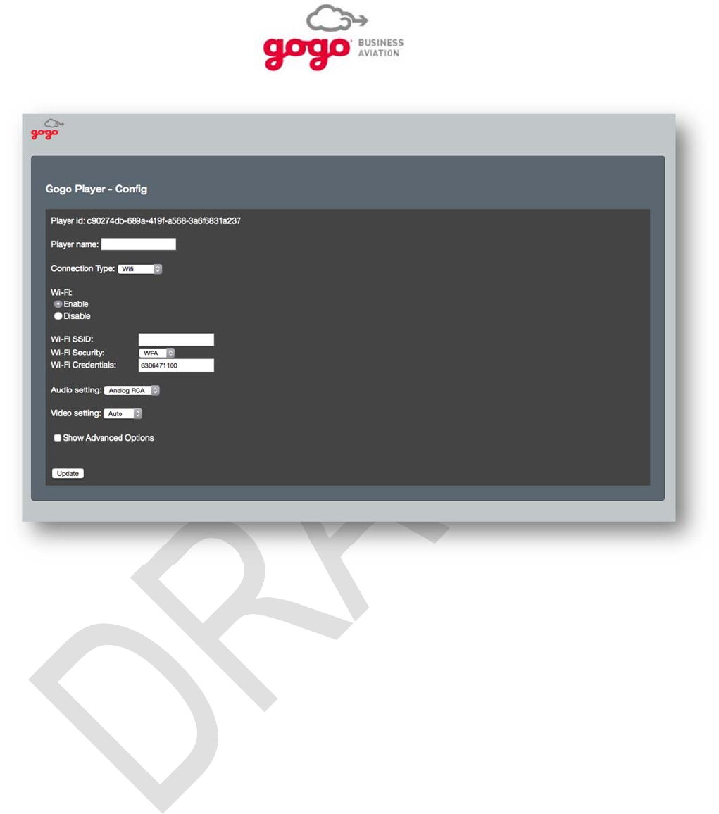
Troubleshooting Procedures, Appendix A Appendix A, Page 3
Gogo Business Aviation confidential and proprietary D18340-A, May 2015
Figure A-1 GVPU Configuration Page
Unit Fails to Output Analog Audio
1. Gain access to the GVPU by removing four fasteners holding the media module in place and
pull it forward. Support the module so it does not fall forward and hang on the wiring.
2. Connect a laptop (Windows 7 Operating System or higher with any Internet browser) to the
GVPU via Ethernet using one of the following methods.
a. If the Ethernet jack, JB1, on the GVPU is available, connect it to the laptop’s RJ-45
Ethernet port with a standard Ethernet cable.
b. If the Ethernet jack, JB1, is not available, connect the laptop’s RJ-45 Ethernet port using
a standard Ethernet cable to the maintenance Ethernet jack.
3. Set a static IP address on the laptop using the following steps:
a. Access the laptop’s Control Panel and select Network and Sharing Center.
b. From the menu on the left side of the window, click on Change Adapter Settings.
c. Right click on the laptop’s Local Area Connection (names may vary) and then click
Properties in the subsequent drop-down menu.

Troubleshooting Procedures, Appendix A Appendix A, Page 4
Gogo Business Aviation confidential and proprietary D18340-A, May 2015
d. In the center table of the new window, click on Internet Protocol Version 4 (TCP/IPv4)
and then click Properties when it is highlighted.
e. If it’s not already highlighted, click the Use the following IP Address: radio button.
Enter the following IP addresses then click OK:
i. IP address: 172.20.10.XX, where XX is between 11 and 99.
ii. Subnet mask: 255.255.255.0
iii. Default gateway: 172.20.10.2
4. On the laptop, open an Internet browser and navigate to the GVPU IP address, 172.20.10.10.
The GVPU Configuration page will open which verifies the GVPU is receiving power.
5. With the Configuration page open, verify Audio Setting is set to Analog RCA. If needed,
change the setting to Analog RCA and then click the Submit button at the bottom of the
screen. Wait for the Configuration page to indicate settings have been saved.
6. Pull the cabin monitor circuit breaker(s)
7. On the GVPU, disconnect the connector from J7.
8. Verify that all sockets on the connecter are seated correctly and free of impediments. Verify
that no pins on the J7 connector are bent.
9. Reset the cabin monitor circuit breaker(s).
10. When the GVPU has booted up, use the laptop browser to access the GVPU Configuration
page (IP address 172.20.10.10). Boot-up will be complete when the Configuration page can be
accessed
11. Set up the following configuration parameters:
a. Connection Type: Ethernet
b. Wi-Fi: Disable
c. Audio Setting: Analog RCA
d. Video Setting: Composite
12. Click the Submit button at the bottom of the screen and wait for acknowledgement that settings
have been accepted.
13. Verify the cabin monitor is set for Composite Video input using the monitor’s remote control.
14. Using a DC voltmeter able to measure above 28 VDC, verify that 28VDC ±4VDC exists at J7
between pin 19 (+28 VDC) and pin 37 (Return).
15. Verify the player has a VHS tape in it and set it to play.
16. With a tape playing, connect an AC voltmeter set to a low range across pins 16 & 35 (Audio
Pass-through Right channel) of the J7 connector and verify the presence of an audio signal
indicated by a variable AC voltage between approximately 10 and 100 mV RMS.
17. With a tape still playing, connect the AC voltmeter across pins 17 & 35 (Audio Pass-through
Left channel) of the J7 connector and verify the presence of an audio signal indicated by a
variable AC voltage between approximately 10 and 100 mV RMS.
18. Pull the cabin monitor circuit breaker(s).
19. On the GVPU, reconnect the connector to J7.

Troubleshooting Procedures, Appendix A Appendix A, Page 5
Gogo Business Aviation confidential and proprietary D18340-A, May 2015
20. Reset the cabin monitor circuit breaker(s).
21. With the tape still playing, verify the presence of the soundtrack on the cabin speakers or
headphone(s) indicating the GVPU is able to output analog.
22. Upon verifying performance, turn off all equipment, push the media module back in place and
secure with fasteners.
Contact Gogo Business Aviation Technical Support for help in evaluating any problem not resolved by
these troubleshooting procedures. Gogo Business Aviation Technical support can be contacted by email
at batechsupport@gogoair.com or, for immediate needs, by telephone at +1-303-301-3278. After any
repair or replacement of a system component, perform an operational check as described in section 4 of
this document.

Troubleshooting Procedures, Appendix A Appendix A, Page 6
Gogo Business Aviation confidential and proprietary D18340-A, May 2015
This Page Intentionally Blank

Instructions for Continued Airworthiness Appendix B, Page 1
Gogo Business Aviation confidential and proprietary D18340-A, May 2015
Instructions for Continued Airworthiness
Design and manufacturing of the GVPU allows for “On Condition Maintenance.” On condition
maintenance means that no periodic service requirements are required to maintain continued
airworthiness of the system. No maintenance is required until the equipment does not perform the
intended function. Cable harness repair, RF cable maintenance, and antenna replacement can be
accomplished in the field. Refer to Appendix A for detailed information on troubleshooting procedures.
Any alteration of this product voids the FAA or Federal Communications Commission (FCC)
certification and the Gogo Business Aviation warranty. Please consult Gogo Business Aviation
Technical Support to help evaluate any problem that is not resolved by following the troubleshooting
procedures in Appendix A. A Return Material Authorization (RMA) is required for all repairs or exchanges
on items returned to Gogo Business Aviation. After obtaining an RMA, return the GVPU to the factory for
repair. If you require an exchange unit to maintain telecommunications operation during Gogo Business
Aviation repairs, please call Customer Service and request that a serviceable unit be sent to you before
removing the installed unit. After factory repair or receiving the serviceable component, consult this
Installation Manual (D18340), Setup and Configuration, to verify proper system operation in the aircraft. If
component is a GVPU, be sure to configure the replacement serviceable unit (call Customer Service @ 1-
888-286-9876) to verify activation of this unit.

Instructions for Continued Airworthiness Appendix B, Page 2
Gogo Business Aviation confidential and proprietary D18340-A, May 2015
This Page Intentionally Blank