Golden Mark FC100 Fan Control User Manual user manual
Golden Mark (HK) Limited Fan Control user manual
user_manual
Fan Controller UG (HS-FC200+)
This product speaks with other
Z-Wave certified devices
Wireless Appliance Control Module
HS-FC200+
In Wall AC Fan Control Switch
INTRODUCTION
GMark HS-FC200+ is designed to replace existing in-wall fan controller and works
with any standard 3-speed or 4-speed AC ceiling fan. The nicely styled unit has 4 LEDs
to indicate speed level and fits a standard decora style wall plate. HS-FC200+ is Z-
Wave Plus certified with S2 level security, SmartStart, and is compatible with major
gateways in the market that support the Z-Wave standard.
FEATURES
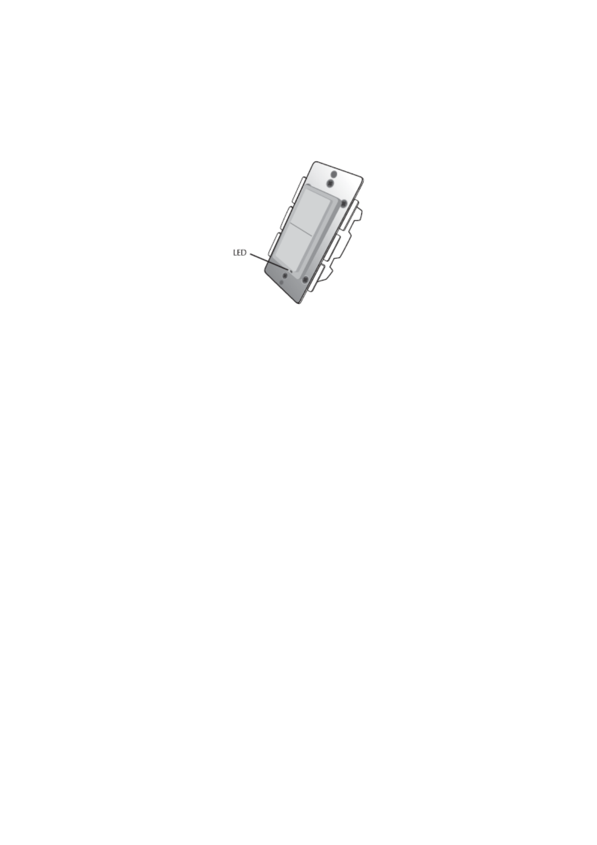
• Modern decora style up and down switch with 4 LED speed status indicator
• LEDs indicate clearly the current fan speed
• Housing and white LED color matches GMark in-wall switch and dimmer
• Fits standard decora style single or multi-gang wall plates
• Single tap key up or down to manually change speeds or control remotely
• Provides Instant Status Change to controller if speed is changed manually
• Screw terminals for easy installation
• Over-The-Air firmware upgrade available with compatible gateways supporting
OTA
! WARNING !
RISK OF FIRE, ELECTRICAL SHOCK & BURNS
DO NOT USE WITH MEDICAL AND LIFE SUPPORT INSTRUMENT
No user serviceable parts are in this module
The appliance connected to HS-FC200+ must not exceed 2.5A loads
IMPORTANT: HS-FC200+ requires LINE, NEUTRAL and LOAD wires for
every installation. Traveler wire required for 3 or 4 way circuits.
• LINE (Hot) - Black (connected to power)
• NEUTRAL - White (this wire is often tied to other neutral wires and may require a jumper to
connect with the HS-FC200+)
• LOAD - Black (usually tied closely to Traveler wire)
• TRAVELER — Red/Other (only used in 3 or 4 -way circuits)
• GROUND — Green or Bare
Fan Controller UG (HS-FC200+)
SETUP
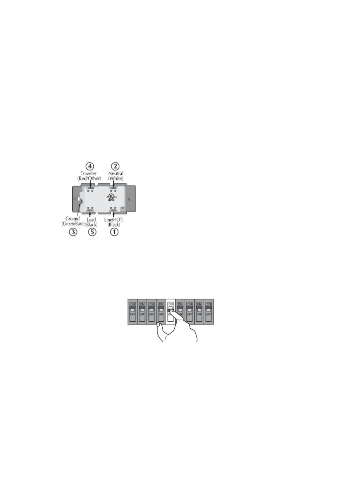
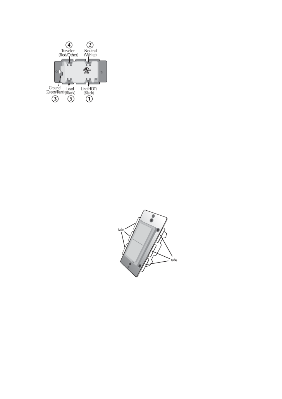
Step 1. Identifying the wiring terminals on the module
Step 2. ! WARNING ! RISK OF SHOCK ! Make sure power if OFF before
wiring !
Step 3.
Remove the wall plate and the existing fan switch (if mounted) at your preferred
installation location. You may label the wires connected to the screw terminals
before disconnecting the switch. Please check that the wiring configuration
below is present in the wall switch box, otherwise consult a qualified electrician.
4 wires for 2-way circuit
5 wires for 3-way circuit
1. Line (Hot) - Black
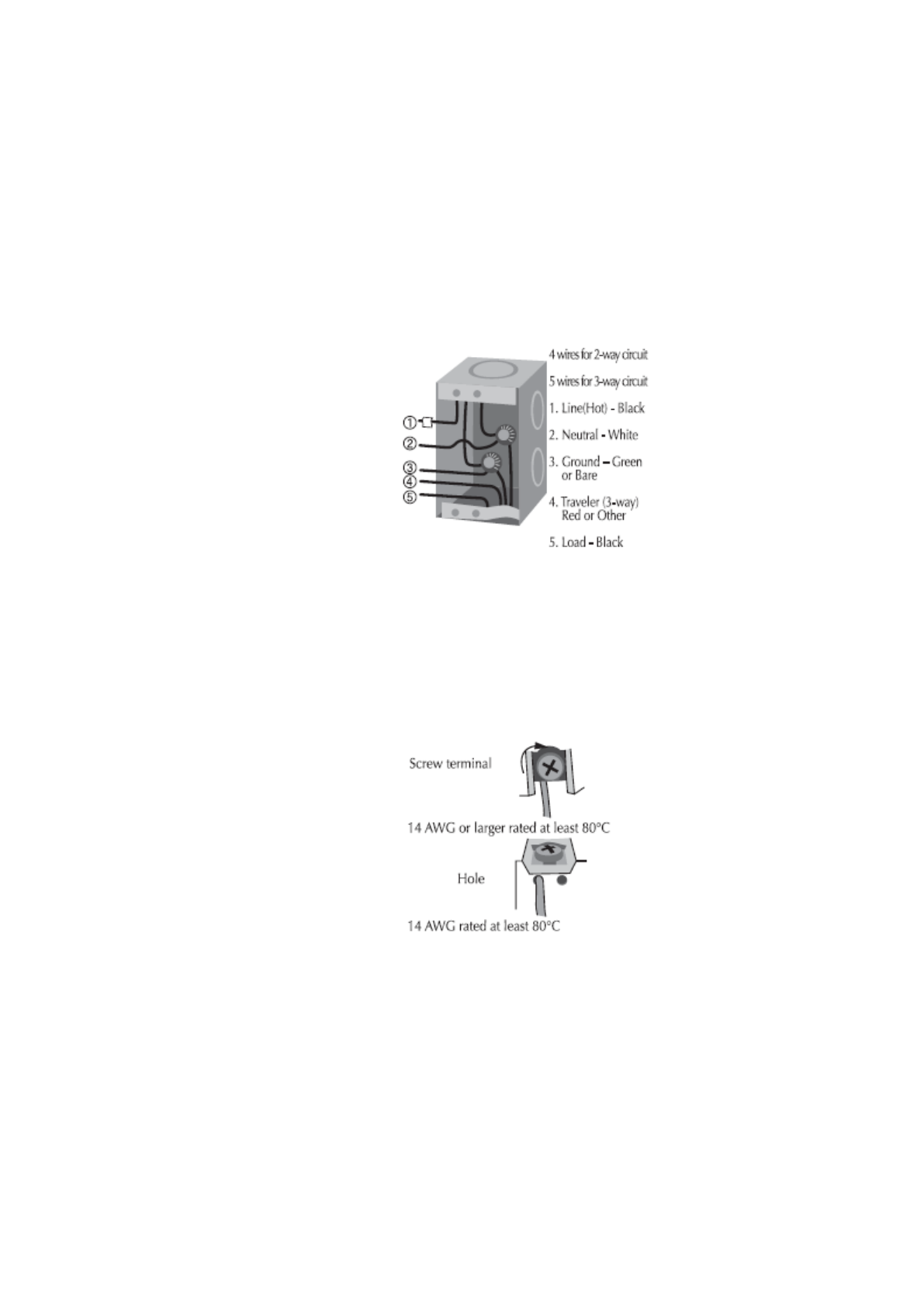
Fan Controller UG (HS-FC200+)
2. Neutral - White
3. Ground – Green or Bare
4. Traveler (3-way) - Red or Other
5. Load – Black
Wiring Information
Use copper wires only
UL specification: the tightening torque for the screws is 14 Kgf-cm (12 lbf-in)
Strip insulation 5/8" (16mm)
Wire connection can be made either to Screw terminal or Hole that is 14 AWG or
larger rated at least 80°C
Fan Controller UG (HS-FC200+)
Hot
Load
Neutral
Neutral
Load
Li ne
120VAC
60Hz
Traveler
FC-100
Ground
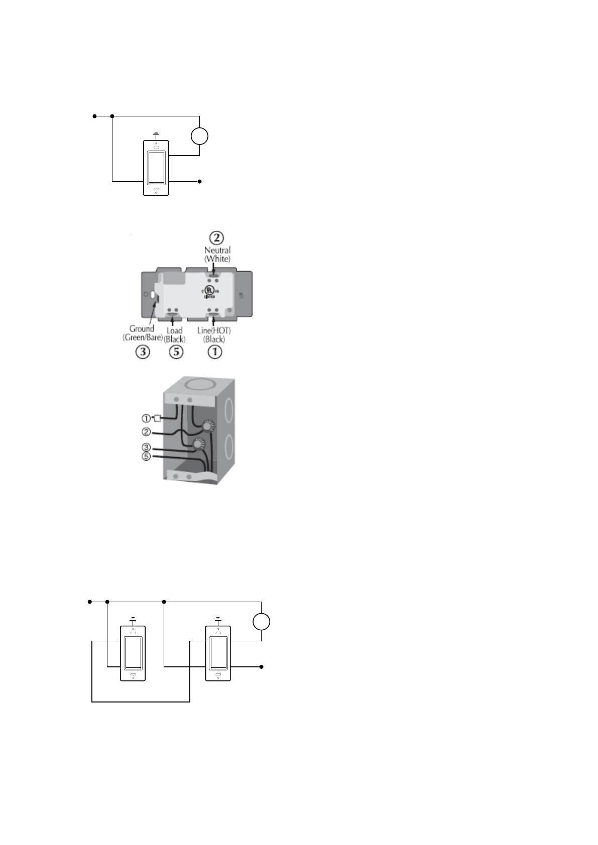
2-way circuit
Making connections
The Traveler terminal is not used in a 2-way circuit. Do not remove the
insulation tape on the Traveler terminal in this application
3-way circuit
Making connections
Hot
Load
NeutralNeutral
Neutral
Load
Li ne
120VAC
60Hz
FC-100
Traveler
Traveler
WA-100
Ground Ground
Fan Controller UG (HS-FC200+)
Please refer to optional 3 way switch WA-100 user manual for wiring
instructions of the auxiliary switch. The maximum length of Traveler wire may
not exceed 200ft.
Gang Box
To install the HS-FC200+ in a multi-gang or J box, the tabs on the sides of the
metal yoke may need to be removed. For single gang switch, no changes is
required. For dual or higher gang configuration where switches are next to
each other, the tabs need to be removed. Simply take a pair of pliers, grab
the tabs and wiggle until the tabs break off.
Step 4.
When proper wiring is completed, secure the module to the wall box. Restore
power to the circuit to test if the connected load can be turned ON/OFF
manually by the rocker on the module before remounting the wall plate. Also
observe the status change of the LED indicator to ensure the module is in
normal operating mode. If WA-100 Auxiliary Switch is used for a 3-way
connection, please also test if it can control the load
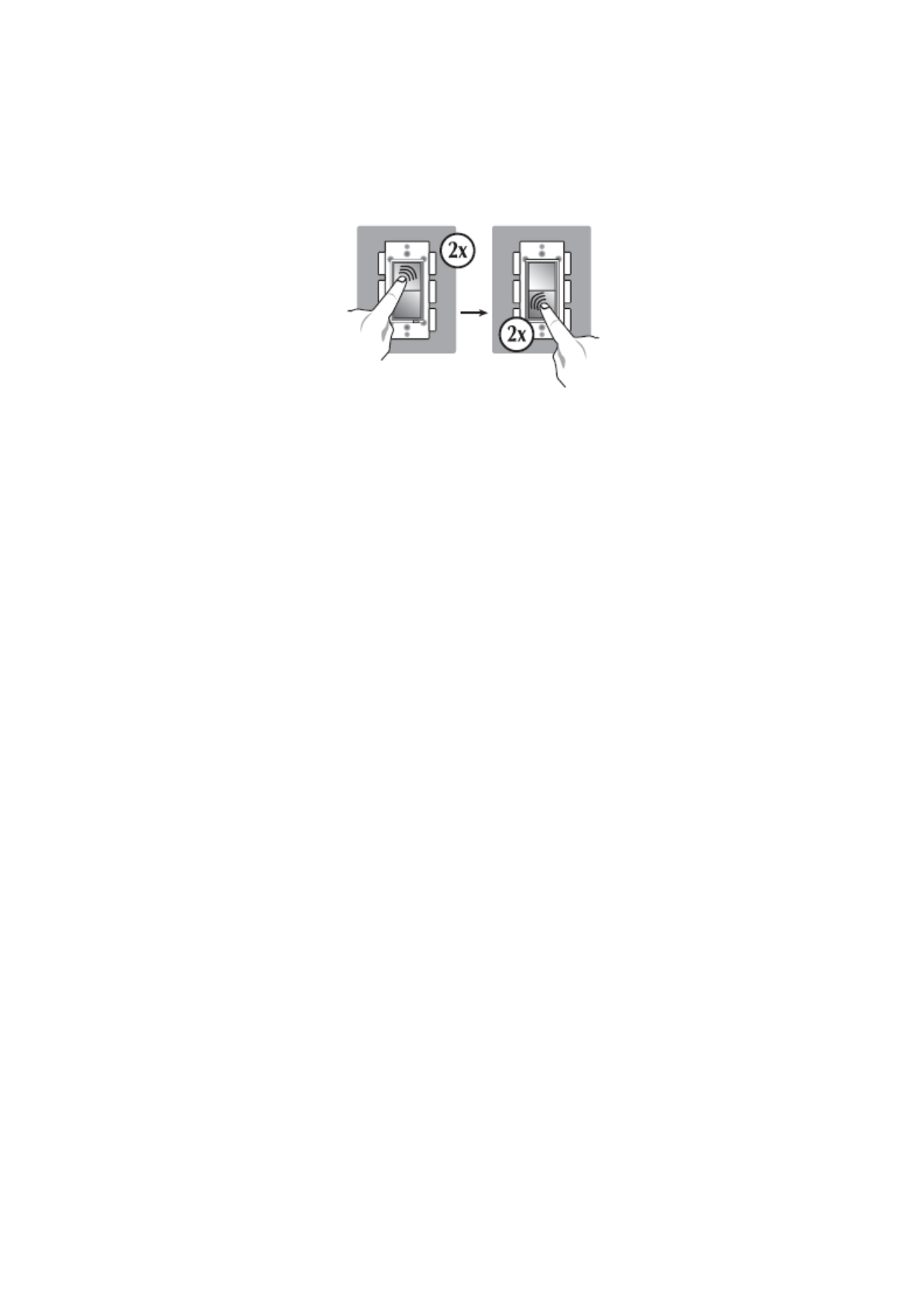
Step 5.
Fan Controller UG (HS-FC200+)
Add (Include) the module into your network by a Z-Wave certified controller.
Please refer to the controller’s instructions manual for details. Normally, this
requires putting your controller software in Add New Device (inclusion) mode.
When this process is initiated in the controller software, single tap the top or
bottom rocker switch. The controller software should indicate that the action
was successful. If the controller shows it was a fail, repeat the procedure.
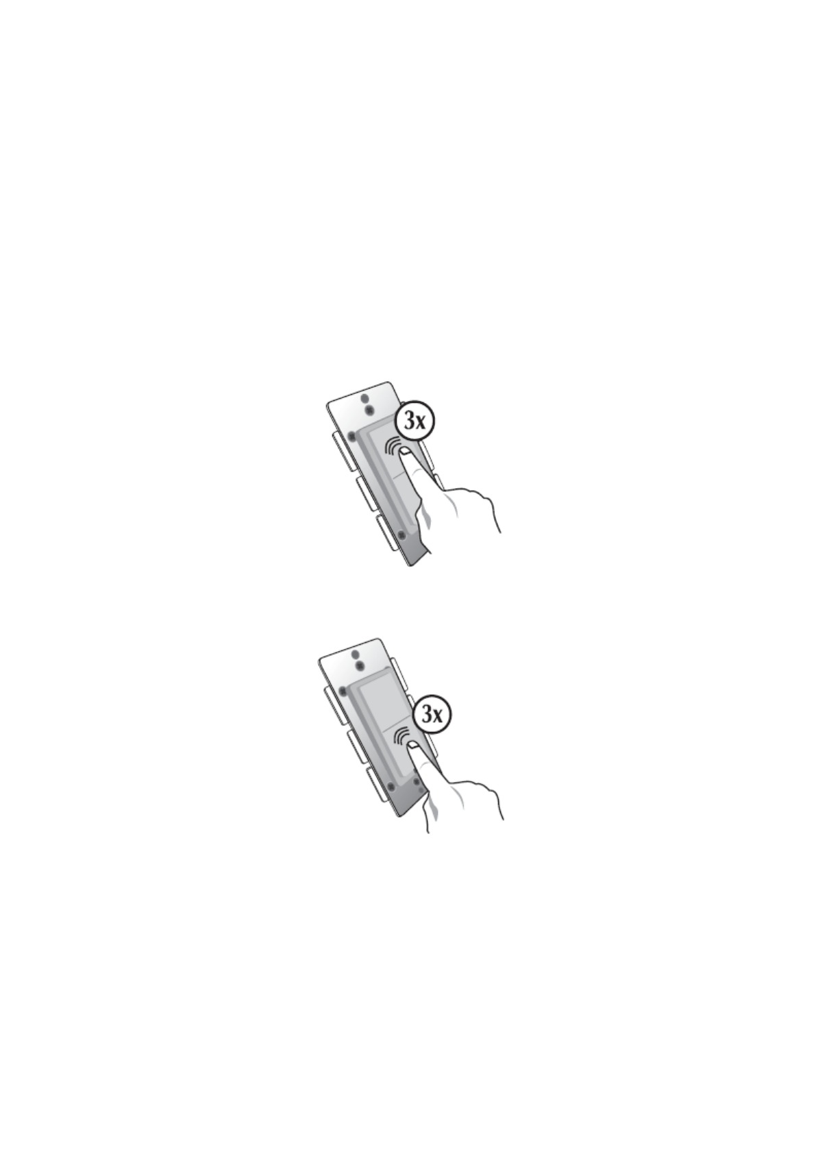
Manual Reset
Note: If Inclusion still fails after the 2nd attempt, you need to first reset the
module before repeating the above steps. The manual reset method is as follows,
Quickly tap the top side (ON) of the rocker 3 times (within one or two seconds).
Then, quickly tap the bottom side (OFF) of the rocker 3 times.
If you see the LED indicator blink, it means that the module has been reset
successfully and you may retry Step. 5 above to add the module into your
network. Otherwise, please repeat the manual reset procedures by speeding up
the clicking action.
Use the manual reset procedure only in the event that the network primary
controller is lost or otherwise inoperable.
BASIC OPERATION
• Fan speed can be controlled by tapping the top (to increase speed) or bottom
(to decrease speed)
• 4 LEDs will clearly indicate the speed of the fan control as follows:
o No LED – Fan is off
Fan Controller UG (HS-FC200+)
o One LED – Fan speed one
o Two LED – Fan speed two
o Three LED – Fan speed three (if you have a 4 speed ceiling fan)
o Four LED – Top speed for 3 speed fan or 4 speed fan)
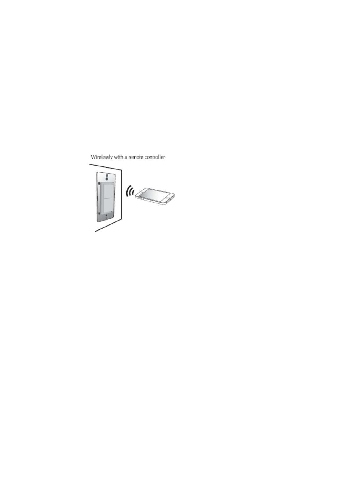
OR
Wirelessly with a remote control app or based on a scheduled program
Once the HS-FC200+ is added to your network, you may assign it to a Group. It
will change its status when the All ON or OFF command is received. Furthermore,
it can be set in Association with another Z-Wave device to perform a specific
function. Please refer to the instructions manual of your gateway or remote
controller for details and procedures on how these settings can be done.
In the event of a power failure, the GMark device will return to the last status
after the power is restored.
Configurable Parameter Settings
If your controller supports Z-Wave configurable parameters, the following
settings can be modified.
Parameter 3 Length: 1 byte
Valid values: 0 or 1 (default 0)
When value = 0, the LED indicator will be OFF when the fan is OFF. When the
value is set to 1, first LED is ON when the fan is off (night light mode)
Parameter 4 Length: 1 byte
Valid values: 0 or 1 (default 0)
If value = 0, the top side of the rocker switch will increase fan speed and bottom
side will decrease speed.
If value= 1, the pressing the bottom side will increase the fan speed and the top
key will decrease speed.
Fan Controller UG (HS-FC200+)
Parameter 5 Length: 1 byte
Valid values: 0 or 1 (default 0)
If value = 0, the fan controller is set for a 3 speed fan.
If value = 1, the fan controller is set for a 4 speed fan.
You can use a Z-Wave certified controller or app from your controller to
communicate with HS-FC200+. Depending on the capability of your controller,
the following simple to advanced operations can be performed. Please refer to
the gateway or controller's manual for details.
1. Turn the fan On or Off and change speed of the fan.
2. Assign HS-FC200+ to a specific Group and control as part of a group of
devices such as All On or Off command
3. Firmware update by Over-The-Air (requires Z-Wave Plus certified gateway
with software support)
Association: Triggered action based on another device in the network
1. HS-FC200+ supports group one for lifeline communication.
2. You can associate up to five Z-Wave devices to group one.
3. Lifeline association only supports the "manual reset" event.
4. For instructions on how to “set lifeline associate”, please refer to your
controller/gateway instructions.
Central Scene
Z-Wave Plus introduced a new process for scene activation called “Central Scene
Control”. If your gateway or controller supports Central Scenes, additional
functions can be performed on HS-FC200+ such as pressing and releasing the
button to send a certain command to the central controller via the lifeline
association group 1. This allows the controller to react to key pressed, key
released and key held down.
- Press and release the top button, Scene 1 preset by the Gateway will be
turned ON.
- Press and release the bottom button, Scene 2 preset by the Gateway will
be turned ON.
Again, this new feature needs to be supported by your controller in order to
enjoy the benefits of this new function. Please consult your controller
manufacturer.

Fan Controller UG (HS-FC200+)
SPECIFICATIONS
Model: HS-FC200+
Supports AC fans with 3 or 4 speeds
Input power: 120 VAC, 60 Hz.
Max output loading: 2.5 amps
Radio frequency: 908.4/916 MHz.
Wireless range: up to 130 ft line of sight between the controller and the other
available nodes.
Normal operating temperature: 77°F (25°C)
For indoor use only.
Interoperability with Z-Wave devices
A Z-Wave network can integrate devices of various classes, and these devices can
be made by different manufacturers.
The GMark product introduced in this instructions manual has a Z-Wave
certification which guarantees such an interoperability.
FCC ID: 2AMY9FC100
The Federal Communication Commission Radio Frequency Interference
Statement includes the following paragraph:
The equipment has been tested and found to comply with the limits for a Class B
Digital Device, pursuant to part 15 of the FCC Rules. These limits are designed to
provide reasonable protection against harmful interference in a residential
installation. This equipment uses, generates and can radiate radio frequency
energy and, if not installed and used in accordance with the instruction, may
cause harmful interference to radio communication. However, there is no
guarantee that interference will not occur in a particular installation. If this
equipment does cause harmful interference to radio or television reception,
which can be determined by turning the equipment off and on, the user is
encouraged to try to correct the interference by one or more of the following
measures:
•Reorient or relocate the receiving antenna
•Increase the separation between the equipment and receiver
•Connect the equipment into an outlet on a circuit different from that to which
the receiver is connected
•Consult the dealer or an experienced radio/TV technician for help
Operation is subject to the following two conditions:
•This device may not cause interference
•This device must accept any interference, including interference that may cause
undesired operation of the device.
Important Note: To comply with the FCC RF exposure compliance requirements,
no change to the antenna or the device is permitted. Any change to the antenna
or the device could result in the device exceeding the RF exposure requirements
and void user’s authority to operate the device.

Fan Controller UG (HS-FC200+)
Caution: Exposure to Radio Frequency Radiation. To comply with FCC/IC RF
exposure compliance requirements, a separation distance of at least 20 cm must
be maintained between the antenna of this device and all persons. This device
must not be co-located or operating in conjunction with any other antenna or
transmitter.
•Reorient or relocate the receiving antenna
•Increase the separation between the equipment and receiver
•Connect the equipment into an outlet on a circuit different from that to which
the receiver is connected
•Consult the dealer or an experienced radio/TV technician for help
IC: 22968-FC100
This device complies with Industry Canada license-exempt RSS standard(s).
Operation is subject to the following two conditions:
1) This device may not cause interference, and
2) This device must accept any interference, including interference that may
cause undesired operation of the device.
Z-Wave is a registered trademark of Sigma Designs
WARRANTY
GMark warrants to the original purchaser of this product that for the warranty
period, this product will be free from material defects in materials and
workmanship. The foregoing warranty is subject to the proper installation,
operation and maintenance of the product in accordance with installation
instructions and the operating manual supplied to customer. Warranty claims
must be made by customer in writing within 30 days of the manifestation of a
problem. GMark's sole obligation under the foregoing warranty is to repair,
replace or correct any such defect that was present at the time of delivery or
during the warranty period. The warranty does not extend to consequential or
incidental damage to other products that may be used with this product. For
inquiry and customer service, email to support@dragontechind.com
All brand names shown are trademarks of their respective owners
Warranty period: limited 1 year from date of purchase
Golden Mark (HK), Ltd.
6/F, Kimberley Plaza, 45-47Kimberley Road
Tsim Sha Tsui, Kowloon, Hong Kong