Golds Gym Ggex628130 Owners Manual
2014-07-19
: Golds-Gym Golds-Gym-Ggex628130-Owners-Manual golds-gym-ggex628130-owners-manual golds-gym pdf
Open the PDF directly: View PDF ![]() .
.
Page Count: 20
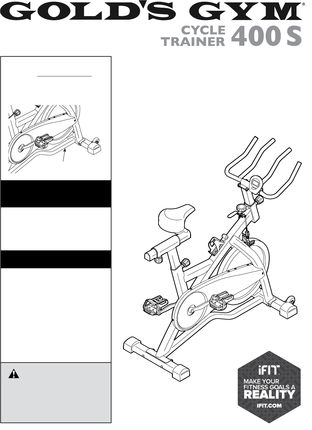
USER’S MANUAL
Serial Number
Decal
CAUTION
Read all precautions and instruc-
tions in this manual before using
this equipment. Keep this manual
for future reference.
Model No. GGEX62813.0
Serial No.
Write the serial number in the space
above for reference.
To register your product and
activate your warranty today, go
to www.workoutwarehouse.com/
registration.
For service at any time, go to
www.workoutwarehouse.com.
Or call 1-877-776-4777
Mon.–Fri. 6 a.m.–6 p.m. MT
Sat. 8 a.m.–12 p.m. MT
Please do not contact the store.
ACTIVATE YOUR
WARRANTY
CUSTOMER CARE
www.workoutwarehouse.com
2
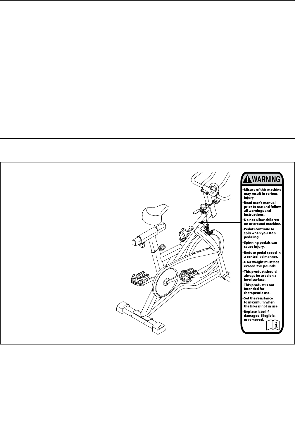
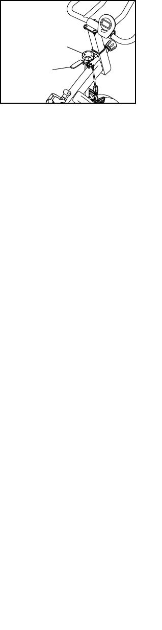
WARNING DECAL PLACEMENT
TABLE OF CONTENTS
WARNING DECAL PLACEMENT . . . . . . . . . . . . . . . . . . . . . . . . . . . . . . . . . . . . . . . . . . . . . . . . . . . . . . . . . . . . . . .2
IMPORTANT PRECAUTIONS ..................................................................3
BEFORE YOU BEGIN. . . . . . . . . . . . . . . . . . . . . . . . . . . . . . . . . . . . . . . . . . . . . . . . . . . . . . . . . . . . . . . . . . . . . . . .5
PART IDENTIFICATION CHART. . . . . . . . . . . . . . . . . . . . . . . . . . . . . . . . . . . . . . . . . . . . . . . . . . . . . . . . . . . . . . . .6
ASSEMBLY . . . . . . . . . . . . . . . . . . . . . . . . . . . . . . . . . . . . . . . . . . . . . . . . . . . . . . . . . . . . . . . . . . . . . . . . . . . . . . . .7
HOW TO USE THE EXERCISE BIKE. . . . . . . . . . . . . . . . . . . . . . . . . . . . . . . . . . . . . . . . . . . . . . . . . . . . . . . . . . .13
FCC INFORMATION . . . . . . . . . . . . . . . . . . . . . . . . . . . . . . . . . . . . . . . . . . . . . . . . . . . . . . . . . . . . . . . . . . . . . . . .16
EXERCISE GUIDELINES ....................................................................17
PART LIST. . . . . . . . . . . . . . . . . . . . . . . . . . . . . . . . . . . . . . . . . . . . . . . . . . . . . . . . . . . . . . . . . . . . . . . . . . . . . . . .18
EXPLODED DRAWING. . . . . . . . . . . . . . . . . . . . . . . . . . . . . . . . . . . . . . . . . . . . . . . . . . . . . . . . . . . . . . . . . . . . . .19
ORDERING REPLACEMENT PARTS .................................................. Back Cover
LIMITED WARRANTY. . . . . . . . . . . . . . . . . . . . . . . . . . . . . . . . . . . . . . . . . . . . . . . . . . . . . . . . . . . . . . . Back Cover
This drawing shows the location(s) of the
warning decal(s). If a decal is missing
or illegible, see the front cover of this
manual and request a free replacement
decal. Apply the decal in the location
shown. Note: The decal(s) may not be
shown at actual size.
GOLD’S GYM is a registered trademark of Gold’s Gym International, Inc.
This product is manufactured and distributed under license from Gold’s Gym Merchandising, Inc.

3
WARNING: To reduce the risk of serious injury, read all important precautions and
instructions in this manual and all warnings on your exercise bike before using your exercise bike.
ICON assumes no responsibility for personal injury or property damage sustained by or through the
use of this product.
IMPORTANT PRECAUTIONS
1. It is the responsibility of the owner to ensure
that all users of the exercise bike are ade-
quately informed of all precautions.
2. Before beginning any exercise program,
consult your physician. This is especially
important for persons over age 35 or per-
sons with pre-existing health problems.
3. Use the exercise bike only as described in
this manual.
4. The exercise bike is intended for home use
only. Do not use the exercise bike in a com-
mercial, rental, or institutional setting.
5. Keep the exercise bike indoors, away from
moisture and dust. Do not put the exercise
bike in a garage or covered patio, or near
water.
6. Place the exercise bike on a level surface
with at least 2 ft. (0.6 m) of clearance around
the exercise bike. To protect the floor or
carpet from damage, place a mat under the
exercise bike.
7. Inspect and properly tighten all parts regu-
larly. Replace any worn parts immediately.
8. Keep children under age 12 and pets away
from the exercise bike at all times.
9. Wear appropriate clothes while exercising;
do not wear loose clothes that could become
caught on the exercise bike. Always wear
athletic shoes for foot protection.
10. The exercise bike should not be used by
persons weighing more than 250 lbs.
(113 kg).
11. Be careful when mounting and dismounting
the exercise bike.
12. Always keep your back straight while using
the exercise bike; do not arch your back.
13. The exercise bike does not have a freewheel;
the pedals will continue to move until the
flywheel stops. Reduce your pedaling speed
in a controlled way.
14. To stop the flywheel quickly, press the brake
lever downward.
15. When the exercise bike is not in use, tighten
the resistance knob completely to prevent
the flywheel from moving.
16. To avoid damaging the brake pads, do not
lubricate the brake pads.
17. Over exercising may result in serious injury
or death. If you feel faint or if you experience
pain while exercising, stop immediately and
cool down.
4
all
STANDARD SERVICE PLANS
5
Thank you for selecting the new GOLD’S GYM®
CYCLE TRAINER 400 S exercise bike. Cycling is an
effective exercise for increasing cardiovascular fitness,
building endurance, and toning the body. The CYCLE
TRAINER 400 S exercise bike provides a selection
of features designed to make your workouts at home
more effective and enjoyable.
For your benefit, read this manual carefully before
you use the exercise bike. If you have questions after
reading this manual, please see the front cover of this
manual. To help us assist you, note the product model
number and serial number before contacting us. The
model number and the location of the serial number
decal are shown on the front cover of this manual.
Before reading further, please familiarize yourself with
the parts that are labeled in the drawing below.
Resistance Knob
Brake Lever
Seat
Adjustment Knobs
Adjustment Knob
Pedal/Strap
Water Bottle Holder*
*Water bottle is not included
Leveling Feet
Console
BEFORE YOU BEGIN
Wheel
Leveling Foot
Length: 3 ft. 10 in. (117 cm)
Width: 1 ft. 8 in. (51 cm)
6
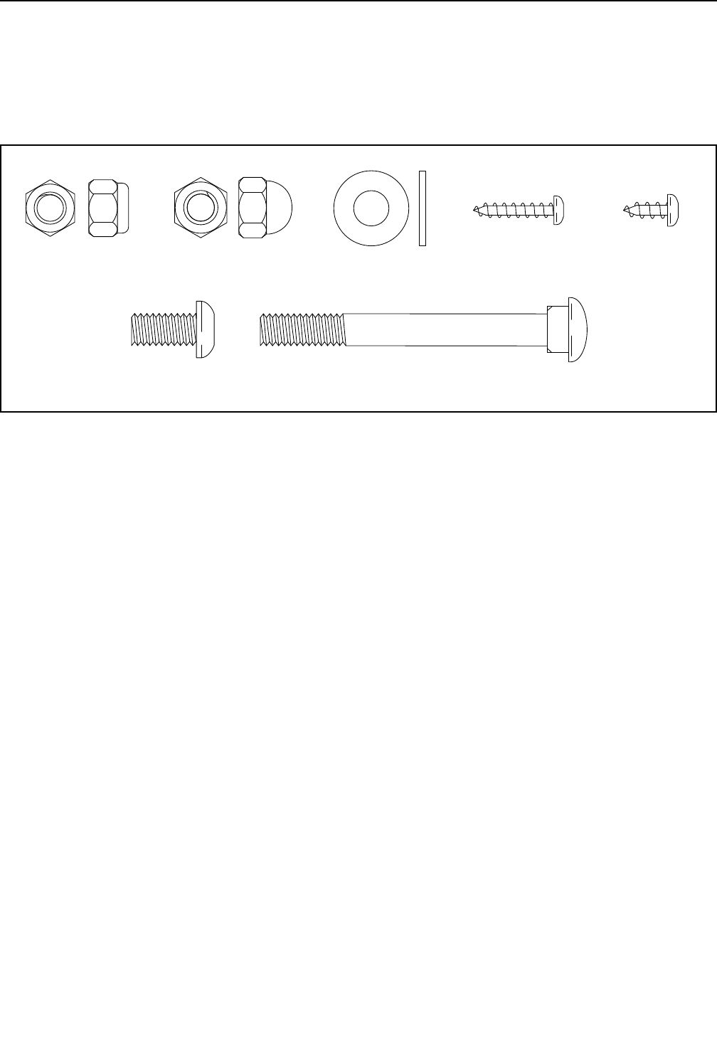
PART IDENTIFICATION CHART
Use the drawings below to identify the small parts needed for assembly. The number in parentheses below each
drawing is the key number of the part, from the PART LIST near the end of this manual. The number following the
key number is the quantity needed for assembly. Note: If a part is not in the hardware kit, check to see if it
has been preassembled. Extra parts may be included.
M8 Locknut
(48)–4
M8 x 16mm
Bolt (25)–4
M8 x 90mm
Carriage Bolt (34)–4
M8 Washer
(33)–8
M8 Acorn
Nut (53)–4
#10 x 12mm
Screw (13)–1
#8 x 20mm
Screw (27)–1
7
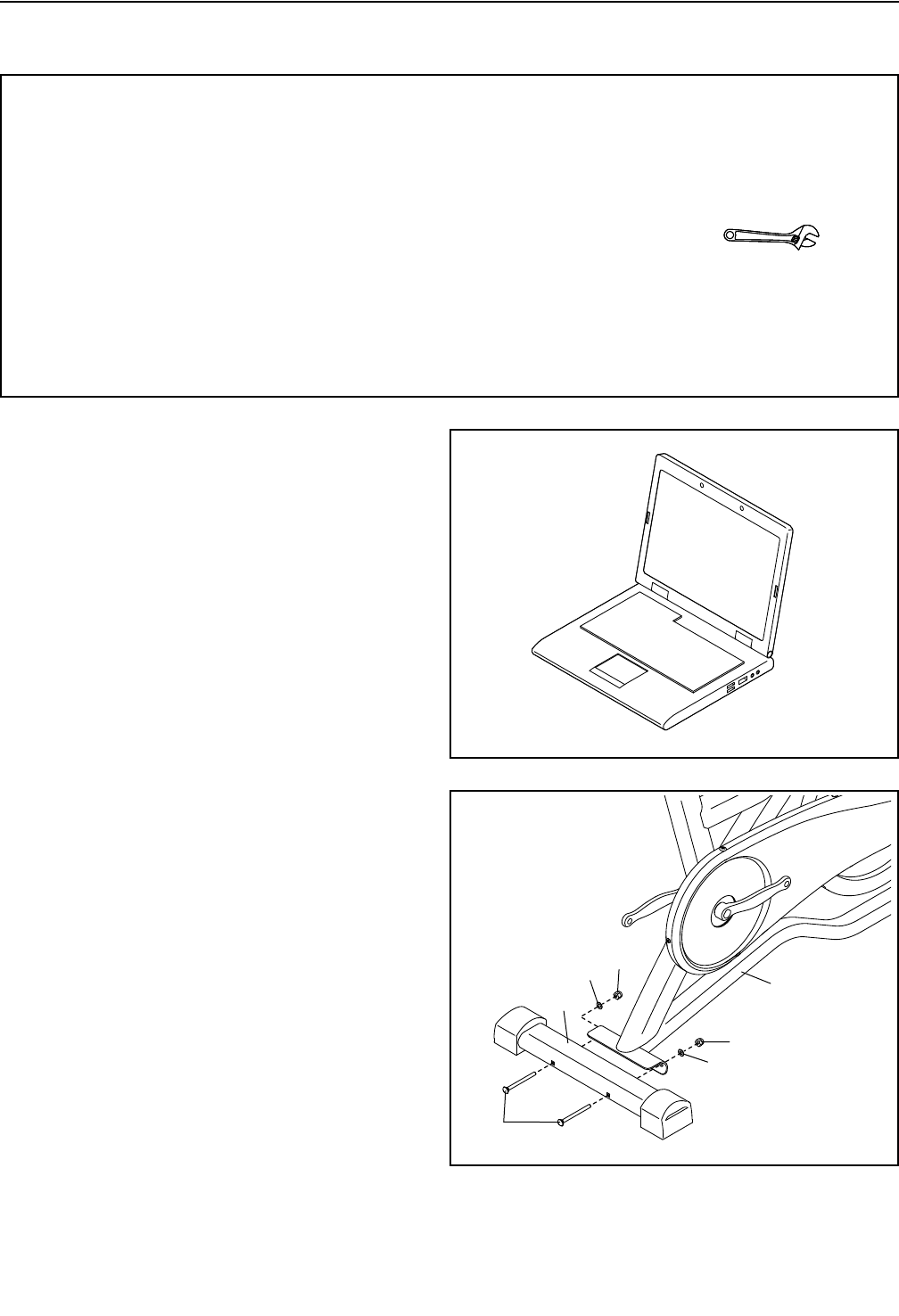
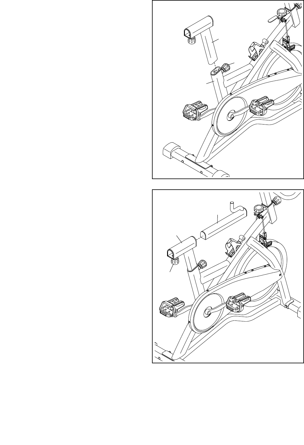
2. If there is a shipping bracket (not shown) on the
rear of the Frame (1), remove and discard the
two screws, the two washers, and the shipping
bracket.
Identify the Rear Stabilizer (7), which does not
have wheels.
Attach the Rear Stabilizer (7) to the Frame (1)
with two M8 x 90mm Carriage Bolts (34), two M8
Washers (33), and two M8 Acorn Nuts (53).
• To hire an authorized service technician to
assemble this product, call 1-800-445-2480.
• Assembly requires two persons.
• Place all parts in a cleared area and remove the
packing materials. Do not dispose of the packing
materialsuntilyounishallassemblysteps.
• Left parts are marked “L” or “Left,” and right parts
are marked “R” or “Right.”
• To identify small parts, see page 6.
• Some parts may be preassembled. Extra parts
may be included.
• In addition to the included tool(s), assembly
requires the following tool(s):
one adjustable wrench
Assembly may be easier if you have a set of
wrenches. To avoid damaging parts, do not use
power tools.
ASSEMBLY
1
7
53
53
33
34
33
2
1. Go to www.workoutwarehouse.com/
registration on your computer and register
your product.
• activatesyourwarranty
• savesyoutimeifyoueverneedtocontact
Customer Care
• allowsustonotifyyouofupgradesandoffers
Note: If you do not have Internet access, call
Customer Care (see the front cover of this
manual) and register your product.
1
8
4
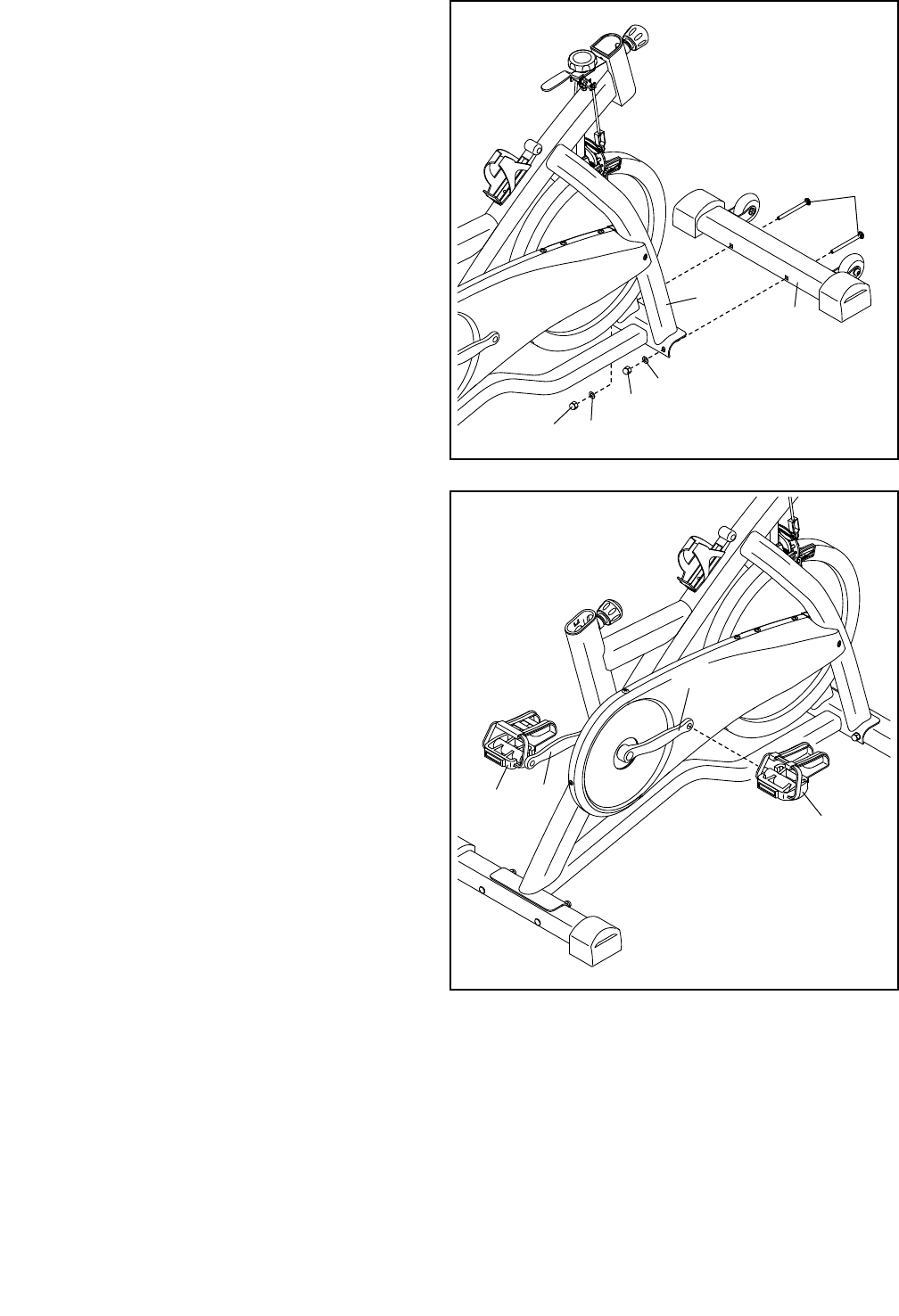
4. Identify the Right Pedal (35).
Using an adjustable wrench, firmly tighten the
Right Pedal (35) clockwise into the Right Crank
Arm (31).
Then, tighten the Left Pedal (45) counterclock-
wise into the Left Crank Arm (12).
45
35
3. If there is a shipping bracket (not shown) on the
front of the Frame (1), remove and discard the
two screws, the two washers, and the shipping
bracket.
Orient the Front Stabilizer (8) as shown.
Attach the Front Stabilizer (8) to the Frame (1)
with two M8 x 90mm Carriage Bolts (34), two M8
Washers (33), and two M8 Acorn Nuts (53).
1
8
34
33
53
3
33
53
12
31
9
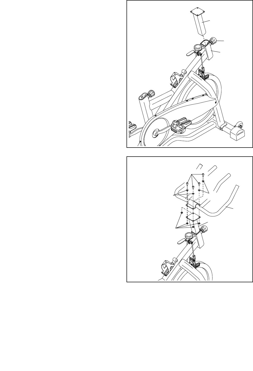
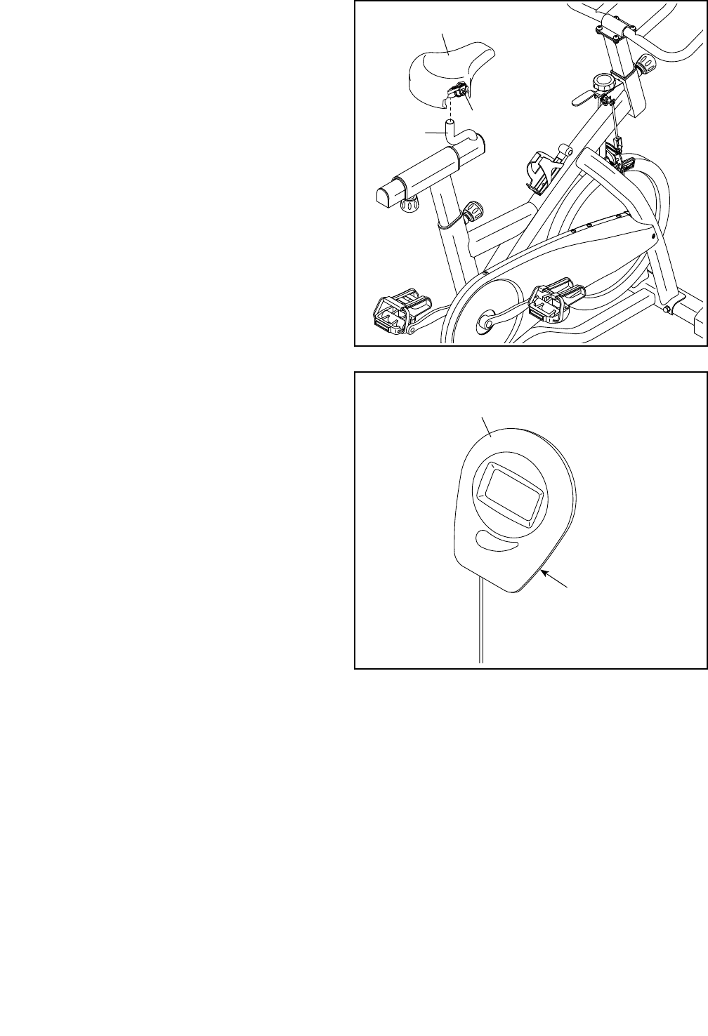
6. Attach the Handlebar (5) to the Handlebar Post
(4) with four M8 x 16mm Bolts (25), four M8
Washers (33), and four M8 Locknuts (48).
6
4
5
25
33
5. Locate the Adjustment Knob (23) on the front of
the Frame (1). Loosen the Adjustment Knob and
pull it outward. Then, insert the Handlebar Post
(4) into the Frame.
Move the Handlebar Post (4) upward or
downward to the desired position, release
the Adjustment Knob (23) into an adjustment
hole in the Handlebar Post, and then tighten
the Adjustment Knob. Make sure that the
Adjustment Knob is firmly engaged in an
adjustment hole.
5
4
23
1
48
33
10
7
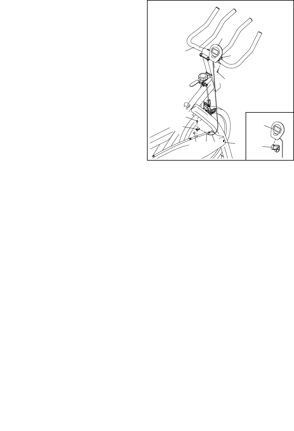
7. Orient the Seat Post (2) as shown.
Locate the Adjustment Knob (23) on the rear of
the Frame (1). Loosen the Adjustment Knob and
pull it outward. Then, insert the Seat Post (2) into
the Frame.
Slide the Seat Post (2) upward or downward
to the desired position, release the Adjustment
Knob (23) into an adjustment hole in the Seat
Post, and then tighten the Adjustment Knob.
Make sure that the Adjustment Knob is firmly
engaged in an adjustment hole.
2
1
23
8
3
2
23
8. Orient the Seat Carriage (3) as shown.
Locate the Adjustment Knob (23) on the Seat
Post (2). Loosen the Adjustment Knob and pull
it downward. Then, insert the Seat Carriage (3)
into the Seat Post.
Slide the Seat Carriage (3) to the desired posi-
tion, release the Adjustment Knob (23) into an
adjustment hole in the Seat Carriage, and then
tighten the Adjustment Knob. Make sure that
the Adjustment Knob is firmly engaged in an
adjustment hole.
11
9
Nut
22
3
9. Slide the Seat (22) onto the post on the Seat
Carriage (3). Make sure that the Seat is level
and that the nose of the Seat is pointing
straight ahead.
Then, tighten the two nuts (only one nut is
shown) beneath the Seat (22).
10. The Console (56) can use two AA batteries (not
included); alkaline batteries are recommended.
Do not use old and new batteries together or
alkaline, standard, and rechargeable batter-
ies together. IMPORTANT: If the Console has
been exposed to cold temperatures, allow
it to warm to room temperature before you
insert batteries. Otherwise, you may damage
the console displays or other electronic com-
ponents. Remove the battery cover from the
back of the console, and insert the batteries into
the battery compartment. Make sure to orient
the batteries as shown by the diagram inside
the battery compartment. Then, reattach the
battery cover.
10
56
Battery
Compartment
12
12. After the exercise bike is assembled, inspect it to make sure that it is assembled correctly and that it
functions properly. Make sure that all parts are properly tightened before you use the exercise bike.
Note: Extra parts may be included. Place a mat beneath the exercise bike to protect the floor.
11. See the inset drawing. Slide the Console (56)
onto the Console Bracket (57).
Attach the Console Bracket (57) to the
Handlebar (5) with a #8 x 20mm Screw (27).
Next, attach the Clamp (58) to the Outer Shield
(14) with a #10 x 12mm Screw (13).
Then, insert the reed switch (A) on the end of the
console wire (B) into the Clamp (58). Move the
reed switch so that it is 1–2 cm away from the
Magnet (59).
56
57
5
27
56
57
11
58
13
AB
59 14
13
HOW TO USE THE EXERCISE BIKE
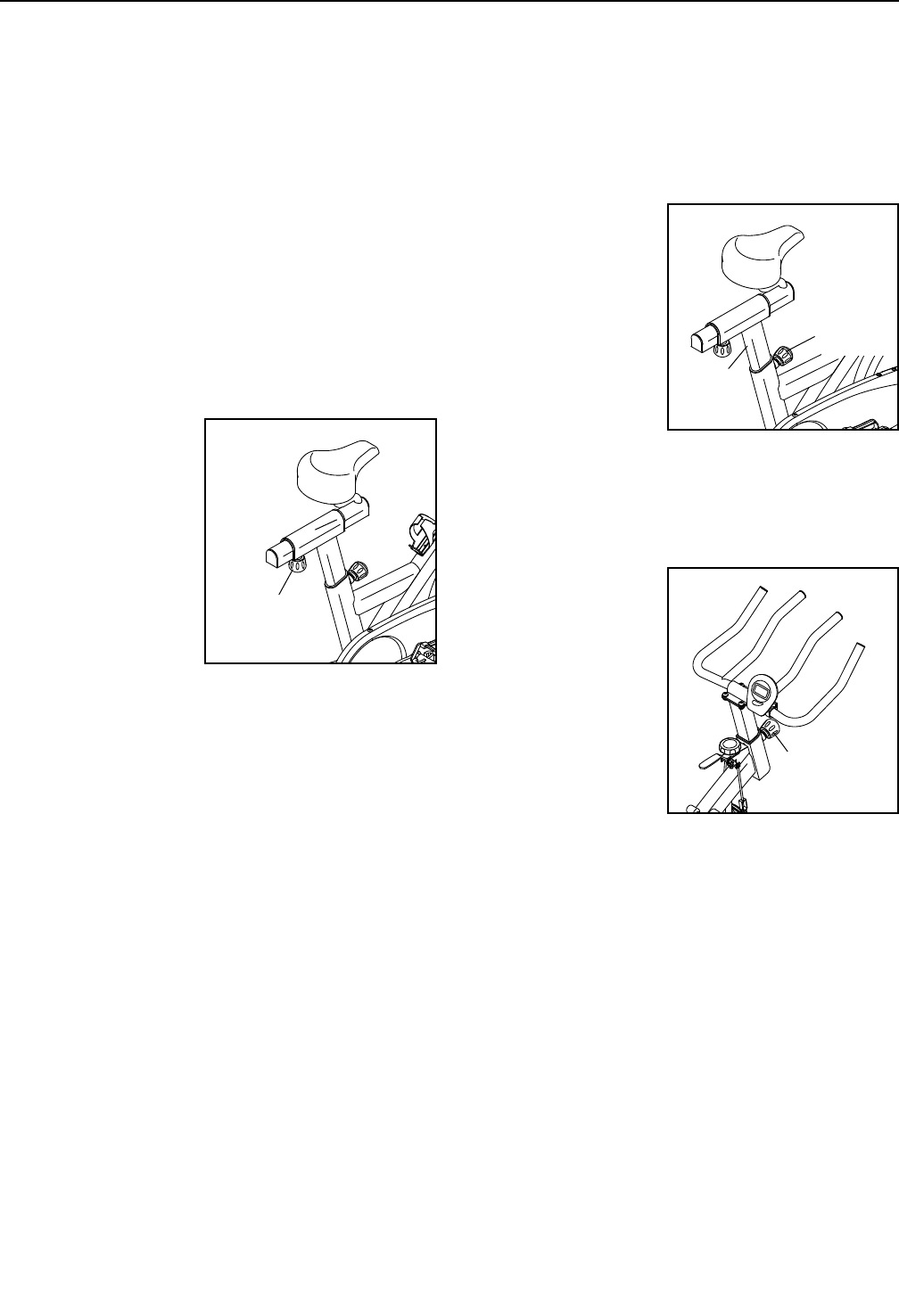
HOW TO ADJUST THE ANGLE OF THE SEAT
You can adjust the angle of the seat to the position that
is most comfortable. You can also slide your seat for-
ward or backward to increase your comfort or to adjust
the distance to the handlebar.
To adjust the seat, see assembly step 9 on page 11.
Loosen the nuts on the seat clamp a few turns, and
then tilt the seat upward or downward or slide the seat
forward or backward to the desired position. Then,
retighten the nuts.
HOW TO ADJUST THE HORIZONTAL POSITION OF
THE SEAT
To adjust the posi-
tion of the seat, first
loosen the adjust-
ment knob and pull
it downward. Then,
move the seat for-
ward or backward,
release the adjust-
ment knob into an
adjustment hole in
the seat carriage,
and firmly tighten the
adjustment knob.
Make sure that the adjustment knob is engaged in
an adjustment hole.
HOW TO ADJUST THE SEAT POST
For effective exercise, the seat should be at the proper
height. As you pedal, there should be a slight bend in
your knees when the pedals are in the lowest position.
To adjust the height
of the seat post, first
loosen the adjust-
ment knob and pull it
outward. Then, move
the seat post upward
or downward, release
the adjustment knob
into an adjustment
hole in the seat post,
and firmly tighten the
adjustment knob.
Make sure that the adjustment knob is engaged in
an adjustment hole.
HOW TO ADJUST THE HANDLEBAR POST
To adjust the height
of the handlebar
post, first loosen the
adjustment knob and
pull it outward. Then,
move the handlebar
post upward or down-
ward, release the
adjustment knob into
an adjustment hole in
the handlebar post,
and firmly tighten the
adjustment knob.
Make sure that the adjustment knob is engaged in
an adjustment hole.
Adjustment
Knob
Adjustment
Knob
Adjustment
Knob
Seat
Post
14
HOW TO ADJUST THE PEDAL STRAPS
To tighten the pedal straps (see the drawing on page
5), simply pull the ends of the pedal straps. To
loosen the pedal straps, press and hold the tabs on the
buckles, adjust the pedal straps to the desired position,
and then release the tabs.
HOW TO ADJUST THE PEDALING RESISTANCE
To increase the
resistance of
the pedals, turn
the resistance
knob clockwise;
to decrease the
resistance, turn the
resistance knob
counterclockwise.
To stop the flywheel, push the brake lever down-
ward. The flywheel should quickly come to a
complete stop.
IMPORTANT: When the exercise bike is not in use,
tighten the resistance knob completely.
HOW TO LEVEL THE EXERCISE BIKE
If the exercise bike rocks slightly on your floor during
use, turn the dials on one or both of the leveling feet
on the front or rear stabilizer (see the drawing on page
5) until the rocking motion is eliminated.
HOW TO MAINTAIN THE EXERCISE BIKE
Inspect and tighten all parts of the exercise bike regu-
larly. Replace any worn parts immediately.
To clean the exercise bike, use a damp cloth and a
small amount of mild detergent. IMPORTANT: To
avoid damage to the console, keep liquids away
from the console and keep the console out of
direct sunlight.
Resistance
Knob
Brake
Lever

15
FEATURES OF THE CONSOLE
The easy-to-use console features six modes that
provide instant exercise feedback during your
workouts.
Scan (SCAN)—This mode displays the time, speed,
distance, calories, and total distance modes, for a few
seconds each, in succession.
Time (TIME)—This mode displays the elapsed time.
Speed (SPEED)—This mode displays your pedaling
speed, in kilometers per hour.
Distance (DIST.)—This mode displays the distance
you have pedaled during your workout, in kilometers.
Calories (CALORIES)—This mode displays the
approximate number of calories you have burned dur-
ing your workout.
Total Distance (TOTAL DIST.)—This mode displays
the total distance, in kilometers, that has been pedaled
on the exercise bike since it was manufactured.
HOW TO USE THE CONSOLE
Make sure that batteries are installed in the console
(see assembly step 10 on page 11). If there is a
sheet of plastic on the console, remove the plastic.
1. Turn on the console.
To turn on the console, press the Mode button on
the console or simply begin pedaling.
2. Select one of the modes.
Scan mode—To select the scan mode, press the
Mode button repeatedly until an arrow appears
above the word SCAN.
Time, speed, distance, calories, or total
distance mode—To select one of these modes
for continuous display, repeatedly press the Mode
button until an arrow appears above the desired
selection. Make sure that an arrow does not appear
above the word SCAN.
3. Begin pedaling and follow your progress with
the display.
As you exercise, the console will display the
mode(s) that you select.
To reset the display to zero, press and hold the
Mode button for several seconds.
4. When you are finished exercising, the console
will turn off automatically.
If the pedals do not move for a few seconds, the
console will pause.
The console has an auto-off feature. If the pedals
do not move and the Mode button is not pressed
for a few minutes, the power will turn off automati-
cally to save the batteries.

16
FCC INFORMATION
This equipment has been tested and found to comply with the limits for a Class B digital device, pursuant to part
15 of the FCC Rules. These limits are designed to provide reasonable protection against harmful interference
in a residential installation. This equipment generates, uses, and can radiate radio frequency energy and, if not
installed and used in accordance with the instructions, may cause harmful interference to radio communications.
However, there is no guarantee that interference will not occur in a particular installation. If this equipment does
cause harmful interference to radio or television reception, which can be determined by turning the equipment off
and on, try to correct the interference by one or more of the following measures:
• Reorientorrelocatethereceivingantenna.
• Increasetheseparationbetweentheequipmentandthereceiver.
• Connecttheequipmentintoanoutletonacircuitdifferentfromthattowhichthereceiverisconnected.
• Consultthedealeroranexperiencedradio/TVtechnicianforhelp.
FCC CAUTION: To assure continued compliance, use only shielded interface cables when connecting to
computer or peripheral devices. Changes or modifications not expressly approved by the party respon-
sible for compliance could void the user’s authority to operate this equipment.
17
These guidelines will help you to plan your exercise
program. For detailed exercise information, obtain a
reputable book or consult your physician. Remember,
proper nutrition and adequate rest are essential for
successful results.
EXERCISE INTENSITY
Whether your goal is to burn fat or to strengthen your
cardiovascular system, exercising at the proper inten-
sity is the key to achieving results. You can use your
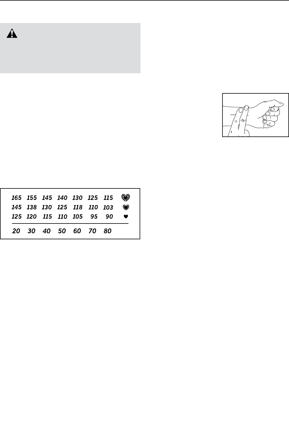
heart rate as a guide to find the proper intensity level.
The chart below shows recommended heart rates for
fat burning and aerobic exercise.
To find the proper intensity level, find your age at the
bottom of the chart (ages are rounded off to the near-
est ten years). The three numbers listed above your
age define your “training zone.” The lowest number is
the heart rate for fat burning, the middle number is the
heart rate for maximum fat burning, and the highest
number is the heart rate for aerobic exercise.
Burning Fat—To burn fat effectively, you must exer-
cise at a low intensity level for a sustained period of
time. During the first few minutes of exercise, your
body uses carbohydrate calories for energy. Only after
the first few minutes of exercise does your body begin
to use stored fat calories for energy. If your goal is to
burn fat, adjust the intensity of your exercise until your
heart rate is near the lowest number in your training
zone. For maximum fat burning, exercise with your
heart rate near the middle number in your training
zone.
Aerobic Exercise—If your goal is to strengthen your
cardiovascular system, you must perform aerobic
exercise, which is activity that requires large amounts
of oxygen for prolonged periods of time. For aerobic
exercise, adjust the intensity of your exercise until your
heart rate is near the highest number in your training
zone.
HOW TO MEASURE YOUR HEART RATE
To measure your heart
rate, exercise for at least
four minutes. Then, stop
exercising and place
two fingers on your
wrist as shown. Take a
six-second heartbeat
count, and multiply the
result by 10 to find your heart rate. For example, if your
six-second heartbeat count is 14, your heart rate is 140
beats per minute.
WORKOUT GUIDELINES
Warming Up—Start with 5 to 10 minutes of stretch-
ing and light exercise. A warm-up increases your body
temperature, heart rate, and circulation in preparation
for exercise.
Training Zone Exercise—Exercise for 20 to 30 min-
utes with your heart rate in your training zone. (During
the first few weeks of your exercise program, do not
keep your heart rate in your training zone for longer
than 20 minutes.) Breathe regularly and deeply as you
exercise; never hold your breath.
Cooling Down—Finish with 5 to 10 minutes of stretch-
ing. Stretching increases the flexibility of your muscles
and helps to prevent post-exercise problems.
EXERCISE FREQUENCY
To maintain or improve your condition, complete three
workouts each week, with at least one day of rest
between workouts. After a few months of regular exer-
cise, you may complete up to five workouts each week,
if desired. Remember, the key to success is to make
exercise a regular and enjoyable part of your everyday
life.
WARNING: Before beginning this
or any exercise program, consult your physi-
cian. This is especially important for persons
over age 35 or persons with pre-existing
health problems.
EXERCISE GUIDELINES

18
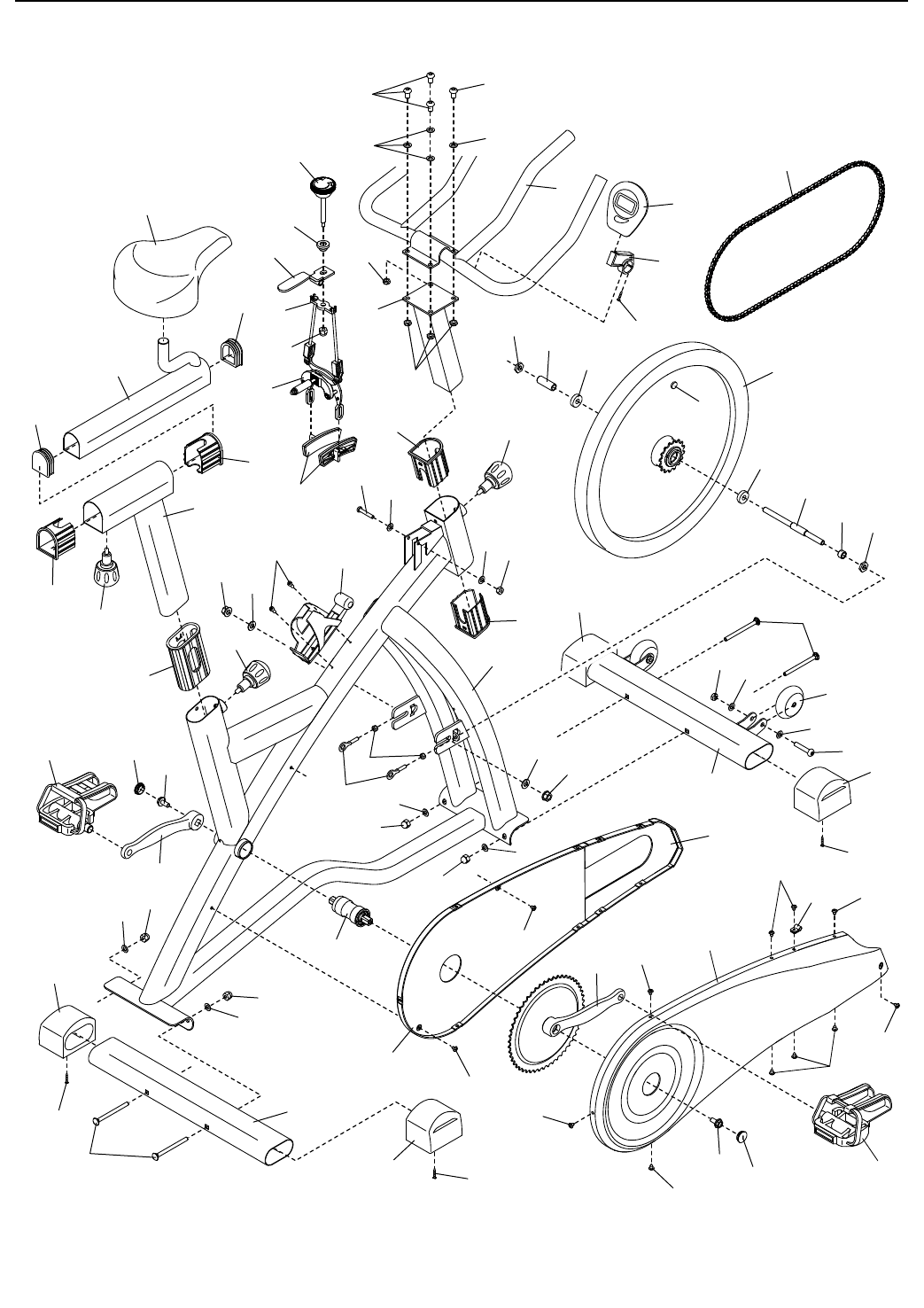
1 1 Frame
2 1 Seat Post
3 1 Seat Carriage
4 1 Handlebar Post
5 1 Handlebar
6 2 Flange Nut
7 1 Rear Stabilizer
8 1 Front Stabilizer
9 1 Brake Lever
10 1 Felt Washer
11 1 Resistance Knob
12 1 Left Crank Arm
13 12 #10 x 12mm Screw
14 1 Outer Shield
15 1 Rear Inner Shield
16 4 Stabilizer Cap
17 2 Seat Post Bushing
18 1 Short Axle Spacer
19 2 Carriage Cap
20 1 Front Inner Shield
21 2 Wheel
22 1 Seat
23 3 Adjustment Knob
24 1 Large Frame Bushing
25 4 M8 x 16mm Bolt
26 1 Caliper Brake Assembly
27 8 #8 x 20mm Screw
28 1 Chain
29 2 M10 Washer
30 1 Bottom Bracket
31 1 Right Crank Arm/Sprocket
32 2 Crank Cap
33 12 M8 Washer
34 4 M8 x 90mm Carriage Bolt
35 1 Right Pedal/Strap
36 1 Flywheel
37 1 Flywheel Axle
38 2 Chain Tensioner
39 1 Long Axle Spacer
40 2 M6 Nut
41 1 Brake Pad Set
42 1 Brake Bracket
43 1 3/8" Square Nut
44 2 Flywheel Bearing
45 1 Left Pedal/Strap
46 2 M8 x 45mm Bolt
47 1 Water Bottle Holder
48 6 M8 Locknut
49 2 M10 Thin Nut
50 1 M6 x 38mm Bolt
51 1 M6 Locknut
52 2 Crank Arm Screw
53 4 M8 Acorn Nut
54 2 M6.5 Washer
55 2 Small Frame Bushing
56 1 Console/Reed Switch/Wire
57 1 Console Bracket
58 1 Clamp
59 1 Magnet
* – Assembly Tool
* – User’s Manual
Key No. Qty. Description Key No. Qty. Description
Note: Specifications are subject to change without notice. For information about ordering replacement parts, see
the back cover of this manual. *These parts are not illustrated.
PART LIST Model No. GGEX62813.0 R1213A
19
1
3
6
68
10
12
5
2
4
7
9
11
14
16
16
16
16
27
27
18
19
19
13
13
13
13
13
13
13
13
27
15
17
17
20
21
23
23
23
26
28
30
32
32
55
55
22
24
29
29
31
34
34
36
38
58
39
33
33
33
33
33
33
35
37
40
41
43
46
42
48
51
50
52
52
45
44
44
47
49
49
48
48
25 25
53
53
53
53
54
54
13
33
27
27
56
57
59
33
EXPLODED DRAWING Model No. GGEX62813.0 R1213A

Part No. 355207 R1213A Printed in China © 2013 ICON IP, Inc.
To order replacement parts, please see the front cover of this manual. To help us assist you, be prepared to
provide the following information when contacting us:
•themodelnumberandserialnumberoftheproduct(seethefrontcoverofthismanual)
•thenameoftheproduct(seethefrontcoverofthismanual)
•thekeynumberanddescriptionofthereplacementpart(s)(seethePARTLISTandtheEXPLODED
DRAWING near the end of this manual)
ORDERING REPLACEMENT PARTS
ICON Health & Fitness, Inc. (ICON) warrants this product to be free from defects in workmanship and
material,undernormaluseandserviceconditions.Theframeiswarrantedforve(5)yearsfromthedate
of purchase. Parts and labor are warranted for ninety (90) days from the date of purchase.
This warranty extends only to the original purchaser (customer). ICON’s obligation under this warranty is
limited to repairing or replacing, at ICON’s option, the product through one of its authorized service centers.
All repairs for which warranty claims are made must be preauthorized by ICON. If the product is shipped
to a service center, freight charges to and from the service center will be the customer’s responsibility. If
replacement parts are shipped while the product is under warranty, the customer will be responsible for a
minimal handling charge. For in-home service, the customer will be responsible for a minimal trip charge.
This warranty does not extend to freight damage to the product. This warranty will automatically be voided
if the product is used as a store display model, if the product is purchased or transported outside the USA,
if all instructions in this manual are not followed, if the product is abused or improperly or abnormally used,
oriftheproductisusedforcommercialorrentalpurposes.Nootherwarrantybeyondthatspecicallyset
forth above is authorized by ICON.
ICON is not responsible or liable for indirect, special, or consequential damages arising out of or in con-
nection with the use or performance of the product; damages with respect to any economic loss, loss of
property,lossofrevenuesorprots,lossofenjoymentoruse,orcostsofremovalorinstallation;orother
consequential damages of any kind. Some states do not allow the exclusion or limitation of incidental or
consequential damages. Accordingly, the above limitation may not apply to the customer.
The warranty extended hereunder is in lieu of any and all other warranties, and any implied warranties of
merchantabilityortnessforaparticularpurposearelimitedintheirscopeanddurationtothetermsset
forth herein. Some states do not allow limitations on how long an implied warranty lasts. Accordingly, the
above limitation may not apply to the customer.
Thiswarrantyprovidesspeciclegalrights;thecustomermayhaveotherrightsthatvaryfromstatetostate.
ICON Health & Fitness, Inc., 1500 S. 1000 W., Logan, UT 84321-9813
LIMITED WARRANTY
IMPORTANT: To protect your fitness equipment with an extended service plan, see page 4.
