Golds Gym Ggtl596060 Owners Manual *PFTL79022 201014
GOLDS_GYM-Treadmill-Crosstrainer_600
crosstrainer 600 GGTL59606 GOLDS_GYM-Treadmill-Crosstrainer_600
2014-07-19
: Golds-Gym Golds-Gym-Ggtl596060-Owners-Manual golds-gym-ggtl596060-owners-manual golds-gym pdf
Open the PDF directly: View PDF ![]() .
.
Page Count: 36

Serial Number Decal
Model No. GGTL59606.0
Serial No.
CAUTION
Read all precautions and instruc-
tions in this manual before using
this equipment. Save this manual
for future reference.
USER'S MANUAL
QUESTIONS?
As a manufacturer, we are com-
mitted to providing complete
customer satisfaction. If you
have questions, or if parts are
damaged or missing, PLEASE
CONTACT OUR CUSTOMER
SERVICE DEPARTMENT
DIRECTLY.
CUSTOMER HOT LINE:
1-877-776-4777
Mon.–Fri. 6 a.m.–6 p.m. MST
Sat. 8 a.m.–5 p.m. MST

TABLE OF CONTENTS
IMPORTANT PRECAUTIONS . . . . . . . . . . . . . . . . . . . . . . . . . . . . . . . . . . . . . . . . . . . . . . . . . . . . . . . . . . . . . . . .3
BEFORE YOU BEGIN . . . . . . . . . . . . . . . . . . . . . . . . . . . . . . . . . . . . . . . . . . . . . . . . . . . . . . . . . . . . . . . . . . . . . .5
ASSEMBLY . . . . . . . . . . . . . . . . . . . . . . . . . . . . . . . . . . . . . . . . . . . . . . . . . . . . . . . . . . . . . . . . . . . . . . . . . . . . . . .6
OPERATION AND ADJUSTMENT . . . . . . . . . . . . . . . . . . . . . . . . . . . . . . . . . . . . . . . . . . . . . . . . . . . . . . . . . . . .11
HOW TO FOLD AND MOVE THE TREADMILL . . . . . . . . . . . . . . . . . . . . . . . . . . . . . . . . . . . . . . . . . . . . . . . . . .23
TROUBLESHOOTING . . . . . . . . . . . . . . . . . . . . . . . . . . . . . . . . . . . . . . . . . . . . . . . . . . . . . . . . . . . . . . . . . . . . .25
CONDITIONING GUIDELINES . . . . . . . . . . . . . . . . . . . . . . . . . . . . . . . . . . . . . . . . . . . . . . . . . . . . . . . . . . . . . . .28
PART LIST . . . . . . . . . . . . . . . . . . . . . . . . . . . . . . . . . . . . . . . . . . . . . . . . . . . . . . . . . . . . . . . . . . . . . . . . . . . . . .30
EXPLODED DRAWING . . . . . . . . . . . . . . . . . . . . . . . . . . . . . . . . . . . . . . . . . . . . . . . . . . . . . . . . . . . . . . . . . . . .32
ORDERING REPLACEMENT PARTS . . . . . . . . . . . . . . . . . . . . . . . . . . . . . . . . . . . . . . . . . . . . . . . . . .Back Cover
LIMITED WARRANTY . . . . . . . . . . . . . . . . . . . . . . . . . . . . . . . . . . . . . . . . . . . . . . . . . . . . . . . . . . . . . .Back Cover
GOLD'S GYM is a registered trademark of Gold's Gym International, Inc. This product is manufactured and
distributed under license from Gold's Gym Merchandising, Inc.
2

1. It is the responsibility of the owner to ensure
that all users of this treadmill are adequately
informed of all warnings and precautions.
2. Use the treadmill only as described.
3. Place the treadmill on a level surface, with at
least eight feet of clearance behind it and two
feet on each side. Do not place the treadmill
on any surface that blocks air openings. To
protect the floor or carpet from damage, place
amat under the treadmill.
4. Keep the treadmill indoors, away from mois-
ture and dust. Do not put the treadmill in a
garage or covered patio, or near water.
5. Do not operate the treadmill where aerosol
products are used or where oxygen is being
administered.
6. Keep children under the age of 12 and pets
away from the treadmill at all times.
7. The treadmill should be used only by persons
weighing 350 pounds or less.
8. Never allow more than one person on the
treadmill at a time.
9. Wear appropriate exercise clothes when
using the treadmill. Do not wear loose clothes
that could become caught in the treadmill.
Athletic support clothes are recommended for
both men and women.
Always wear athletic
shoes. Never use the treadmill with bare feet,
wearing only stockings, or in sandals.
10. When connecting the power cord (see page
11), plug the power cord into a surge sup-
pressor (not included) and plug the surge
suppressor into a grounded circuit capable of
carrying 15 or more amps. No other appliance
should be on the same circuit. Do not use an
extension cord.
11. Use only a single-outlet surge suppressor
that meets all of the specifications described
on page 11. To purchase a surge suppressor,
see your local GOLD’S GYM dealer or call the
toll-free telephone number on the front cover
of this manual and order part number 146148,
or see your local electronics store.
12. Failure to use a properly functioning surge
suppressor could result in damage to the con-
trol system of the treadmill. If the control sys-
tem is damaged, the walking belt may change
speed, accelerate, or stop unexpectedly,
which may result in a fall and serious injury.
13. Keep the power cord and the surge suppres-
sor away from heated surfaces.
14. Never move the walking belt while the power
is turned off. Do not operate the treadmill if
the power cord or plug is damaged, or if the
treadmill is not working properly. (See TROU-
BLESHOOTING on page 25 if the treadmill is
not working properly.)
15. Read, understand, and test the emergency
stop procedure before using the treadmill (see
HOW TO TURN ON THE POWER on page 13).
16. Never start the treadmill while you are stand-
ing on the walking belt. Always hold the
handrails while using the treadmill.
17. The treadmill is capable of high speeds.
Adjust the speed in small increments to avoid
sudden jumps in speed.
18. The pulse sensor is not a medical device.
Various factors, including the user's move-
ment, may affect the accuracy of heart rate
readings. The pulse sensor is intended only
as an exercise aid in determining heart rate
trends in general.
19. Never leave the treadmill unattended while it
is running. Always remove the key, unplug
the power cord, and switch the reset/off cir-
cuit breaker to the off position when the
treadmill is not in use. (See the drawing on
page 5 for the location of the circuit breaker.)
20. Do not attempt to raise, lower, or move the
treadmill until it is properly assembled. (See
ASSEMBLY on page 6, and HOW TO FOLD
AND MOVE THE TREADMILL on page 23.)
You must be able to safely lift 45 pounds (20
kg) to raise, lower, or move the treadmill.
WARNING: Toreduce the risk of burns, fire, electric shock, or injury to persons, read the
following important precautions and information before operating the treadmill.
IMPORTANT PRECAUTIONS
3
4
50%
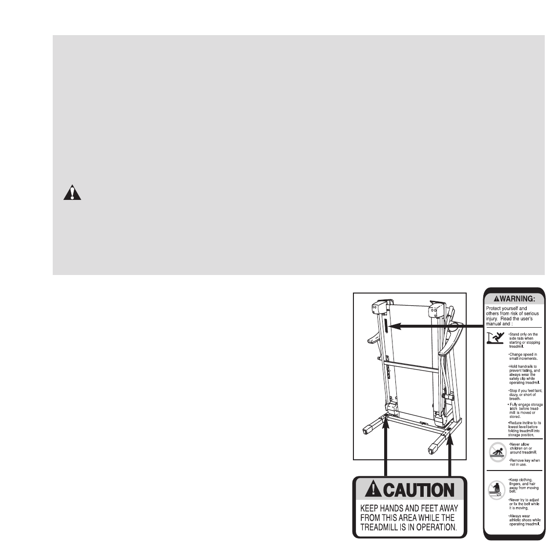
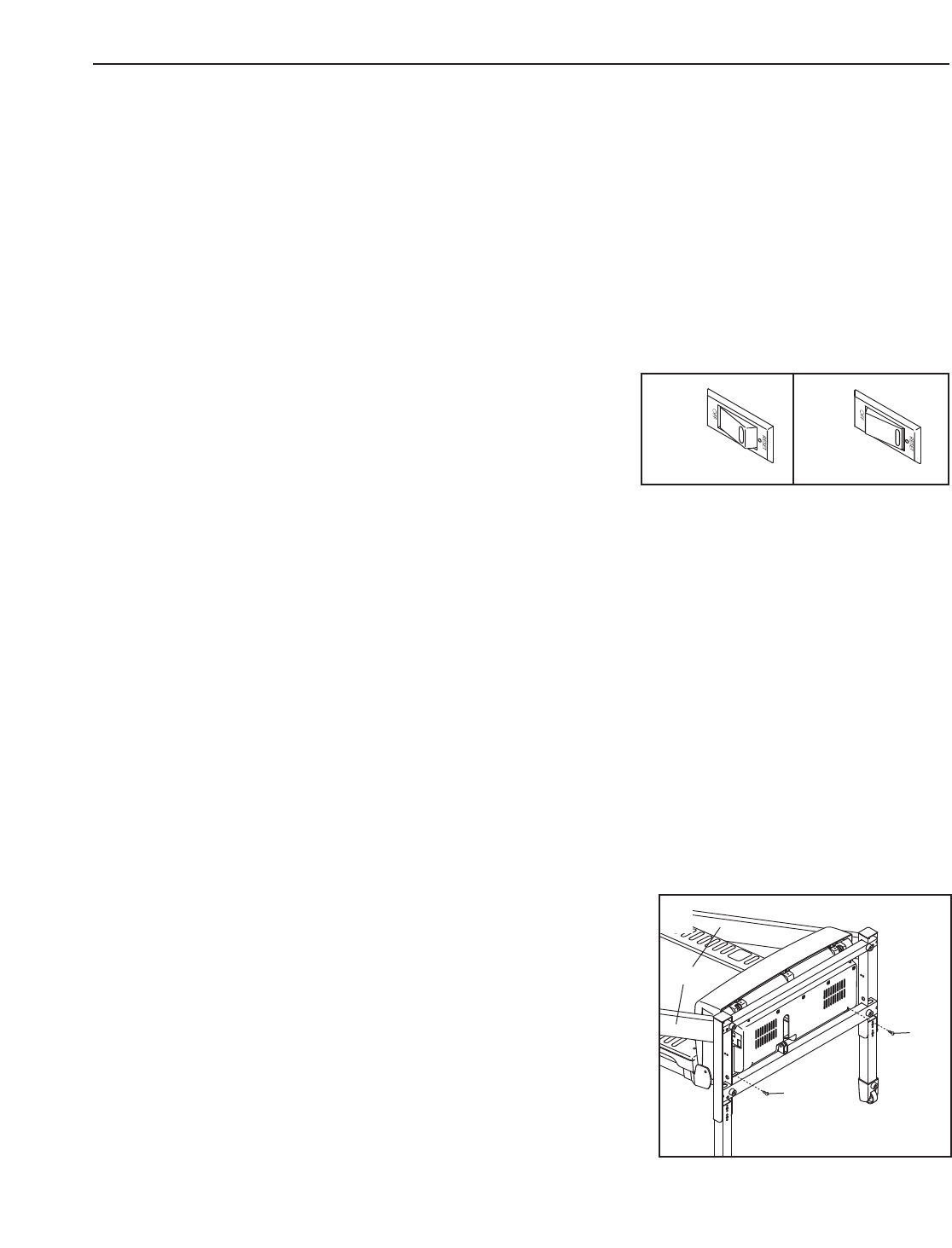
The decals shown here have been placed on the treadmill. If
adecal is missing, or if it is not legible, call the toll-free tele-
phone number on the front cover of this manual and order a
free replacement decal. Apply the decal in the location
shown.
21. When folding or moving the treadmill, make
sure that the storage latch is fully closed.
22. Inspect and properly tighten all parts of the
treadmill regularly.
23. Never insert any object into any opening.
24. DANGER: Always unplug the power
cord immediately after use, before cleaning the
treadmill, and before performing the mainte-
nance and adjustment procedures described in
this manual. Never remove the motor hood un-
less instructed to do so by an authorized ser-
vice representative. Servicing other than the
procedures in this manual should be performed
by an authorized service representative only.
25. This treadmill is intended for in-home use
only. Do not use this treadmill in a commer-
cial, rental, or institutional setting.
WARNING: Before beginning this or any exercise program, consult your physician. This
is especially important for persons over the age of 35 or persons with pre-existing health problems.
Read all instructions before using. ICON assumes no responsibility for personal injury or property
damage sustained by or through the use of this product.
SAVE THESE INSTRUCTIONS
5
Thank you for selecting the revolutionary GOLD’S
GYM®CROSSTRAINER 600 treadmill. The
CROSSTRAINER 600 treadmill offers an impressive
array of features designed to make your workouts at
home more enjoyable and effective. And when you’re
not exercising, the unique CROSSTRAINER 600 tread-
mill can be folded up, requiring less than half the floor
space of other treadmills.
For your benefit, read this manual carefully before
you use the treadmill. If you have questions after
reading this manual, please see the front cover of this
manual. To help us assist you, note the product model
number and serial number before contacting us. The
model number of the treadmill is GGTL59606.0. The
serial number can be found on a decal attached to the
treadmill (see the front cover of this manual for the lo-
cation).
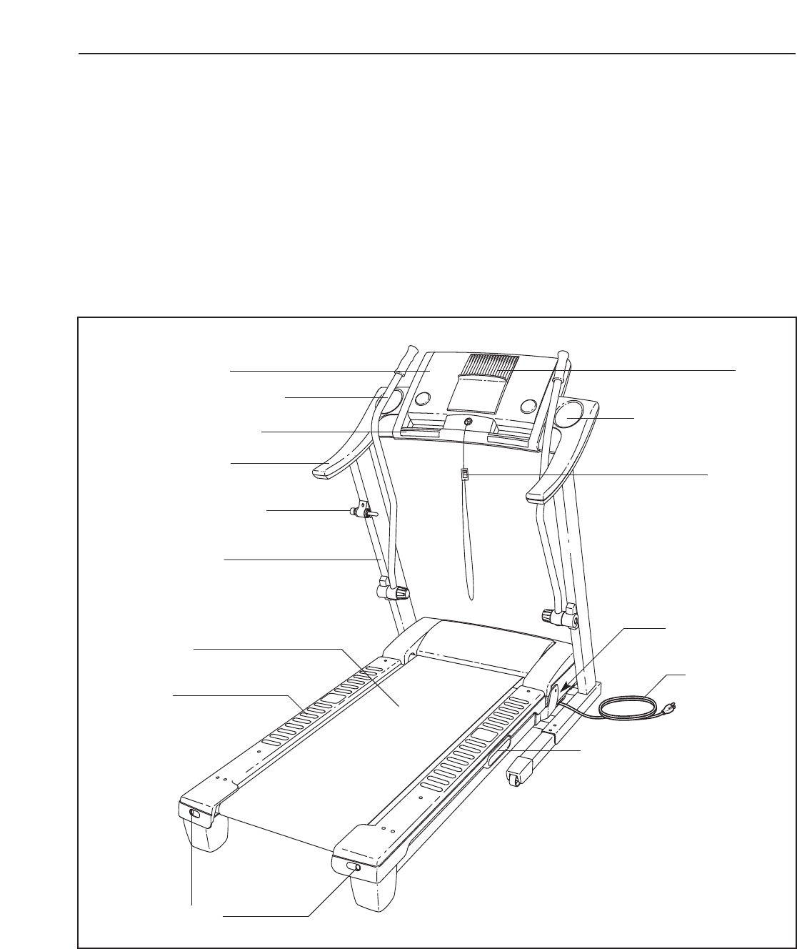
Before reading further, please review the drawing
below and familiarize yourself with the labeled parts.
BEFORE YOU BEGIN
Handrail
Upright
Storage Latch
Key/Clip
Reset/Off
Circuit Breaker
Walking Belt
Cushioned Walking Platform
Foot Rail
Power Cord
RIGHT SIDE
Rear Roller
Adjustment Bolts
Console
Pulse Sensor
Water Bottle Holder
(bottle not included)
Fan
Upper Body Arm
BACK
1. Make sure that the power cord is unplugged.
With the help of a second person, carefully tip
the treadmill onto its left side. Partially fold the
Frame (58) so the treadmill is more stable. Do
not fully fold the Frame until the treadmill is
completely assembled.
Identify the Right Upright (107) and the Left
Upright (84) (the Left Upright has two small
holes in the indicated location).
Hold the Right Upright (107) near the Base (108)
at the angle shown. Feed the end of the Wire
Harness (77) into the hole in the Base, into the
bottom of the Right Upright, and out of the top.
1
6
ASSEMBLY
Assembly requires two persons. Set the treadmill in a cleared area and remove all packing materials. Do not
dispose of the packing materials until assembly is completed. Note: The underside of the treadmill walking belt is
coated with high-performance lubricant. During shipping, lubricant may be transferred to the top of the walking
belt or the shipping carton. This is a normal condition and does not affect treadmill performance. If there is lubri-
cant on top of the walking belt, simply wipe off the lubricant with a soft cloth and a mild, non-abrasive cleaner.
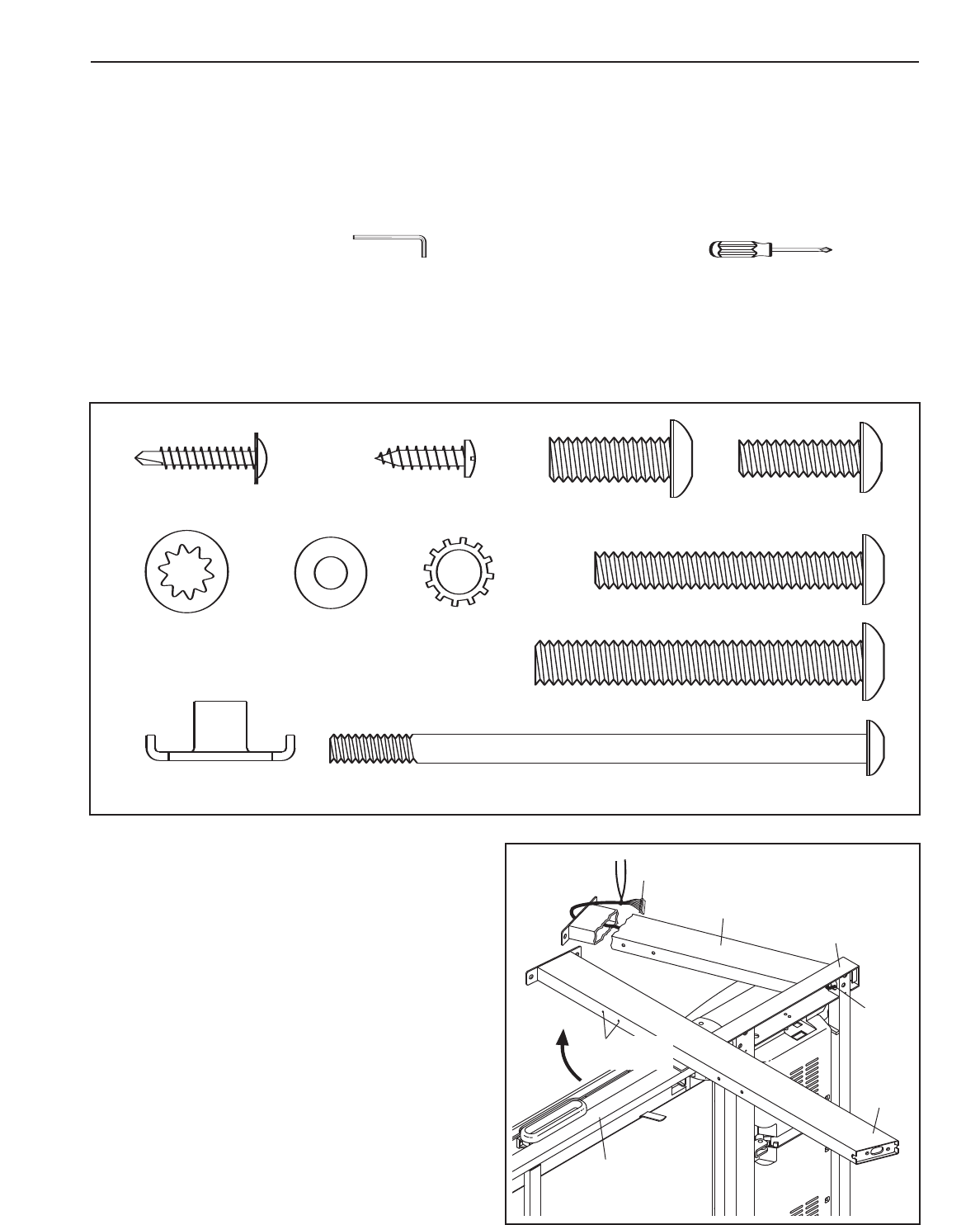
Assembly requires the included hex key and your own phillips screwdriver .
For help identifying the assembly hardware, see the drawings below. The number in parentheses below each
drawing is the key number of the part, from the PART LIST on page 30. The number following the parentheses is
the quantity needed for assembly. Note: Some small parts may have been preassembled. If a part is not in
the parts bag, check to see if it has been preassembled. To avoid damaging plastic parts, do not use
power tools for assembly.
84
58
107
77
77
108
Wheel Nut (13)–2
1
Wheel Nut (32)–2
( )
Handrail Bolt (64)–4
3 1/2” Bolt (45)–4
Extension Leg Bolt (96)–4
3
Star Washer
(84)–2
1" Tek Screw (83)–4
Star Washer (8)–4
Extension Leg Nut (67)–4
Screw (3)–2
Extension Leg Bolt (65)–4
Flat Washer
(102)–4
4 1/2" Bolt (103)–4
3/8" Star
Washer (23)–8
2 3/4" Upright Bolt (105)–2
Console Bolt (64)–4
1" Upright Bolt
(106)–2
Extension Leg Bolt (96)–4
Small Holes
3. Attach two Base Pads (82) to the Base (108)
with two 1” Tek Screws (83) as shown.
Insert an Extension Leg (89) into the Base (108)
as shown. Hold two Extension Leg Nuts (67) in
the bottom of the Extension Leg. Next, insert
two Extension Leg Bolts (65) into the top of the
Extension Leg, and firmly tighten the Extension
Leg Bolts into the Extension Leg Nuts.
3
89
82
82
108
83
65
67
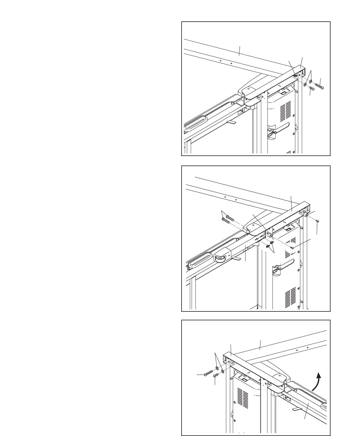
4. With the help of a second person, carefully tip
the treadmill onto its other side. Partially fold the
Frame (58) so the treadmill is more stable. Do
not fully fold the Frame until the treadmill is
completely assembled.
Attach the Left Upright (84) to the Base (108)
with a 1" Upright Bolt (106), a 2 3/4" Upright Bolt
(105), and two Star Washers (23). Do not fully
tighten the Upright Bolts yet.
4
108
58
84
106
23
105
7
2. Hold the Right Upright (107) against the Base
(108). Be careful not to pinch the Upright
Wire (77).
Attach the Right Upright (107) to the Base (108)
with a 1" Upright Bolt (106), a 2 3/4" Upright Bolt
(105), and two Star Washers (23). Do not fully
tighten the Upright Bolts yet.
2
23
77
107
105
106
108
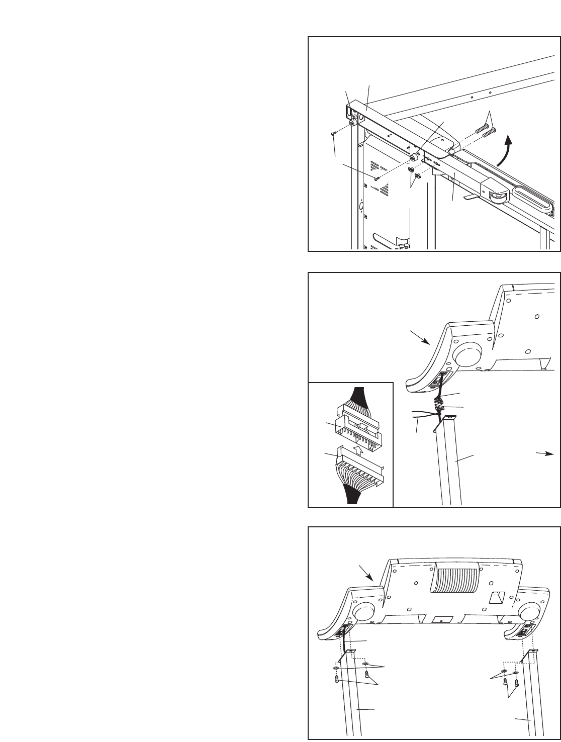
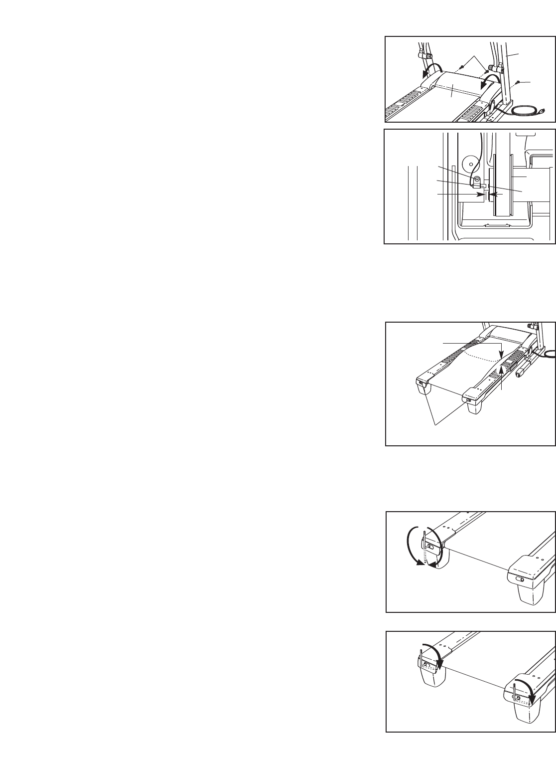
7. Insert the Wire Harness (77) and the Console
Wire (66) into the Right Upright (107).
Set the console assembly on the Left Upright
(84) and the Right Upright (107). Be careful to
avoid pinching the wires. While a second per-
son holds the console assembly, attach it to the
Uprights with four Console Bolts (64) and four
Star Washers (8) as shown; start all four
Console Bolts and then firmly tighten them.
Plug in the power cord as described on page
11, and turn on the power as described on page
13. Note: The treadmill may automatically rise to
the maximum incline level and then return to the
minimum level. Adjust the incline to the lowest
inline level as described in step 4 on page 13.
7
Console
Assembly
64
77, 66
64
8
8
107 84
6. With the help of a second person, carefully raise
the Uprights (84, 107) to a vertical position.
Have the second person hold the console as-
sembly near the Right Upright (107) as shown.
Look under the console assembly and locate
the console wire.
Remove the tie from the Wire Harness (77).
Connect the Wire Harness to the Console Wire
(66). Make sure to connect the connectors
properly (see the inset drawing). The con-
nectors should slide together easily and
snap into place. If they do not, turn one con-
nector and try again. IF THE CONNECTORS
ARE NOT CONNECTED PROPERLY, THE
CONSOLE MAY BE DAMAGED WHEN THE
POWER IS TURNED ON.
6
107
Tie
77
66
Console
Assembly
77
66
8
5. Attach two Base Pads (82) to the Base (108)
with two 1” Tek Screws (83) as shown.
Insert the other Extension Leg (89) into the
Base (108) as shown. Hold two Extension Leg
Nuts (67) in the bottom of the Extension Leg.
Next, insert two Extension Leg Bolts (65) into
the top of the Extension Leg, and firmly tighten
the Extension Leg Bolts into the Extension Leg
Nuts.
5
89
82
82
108
83
65
67
84
9
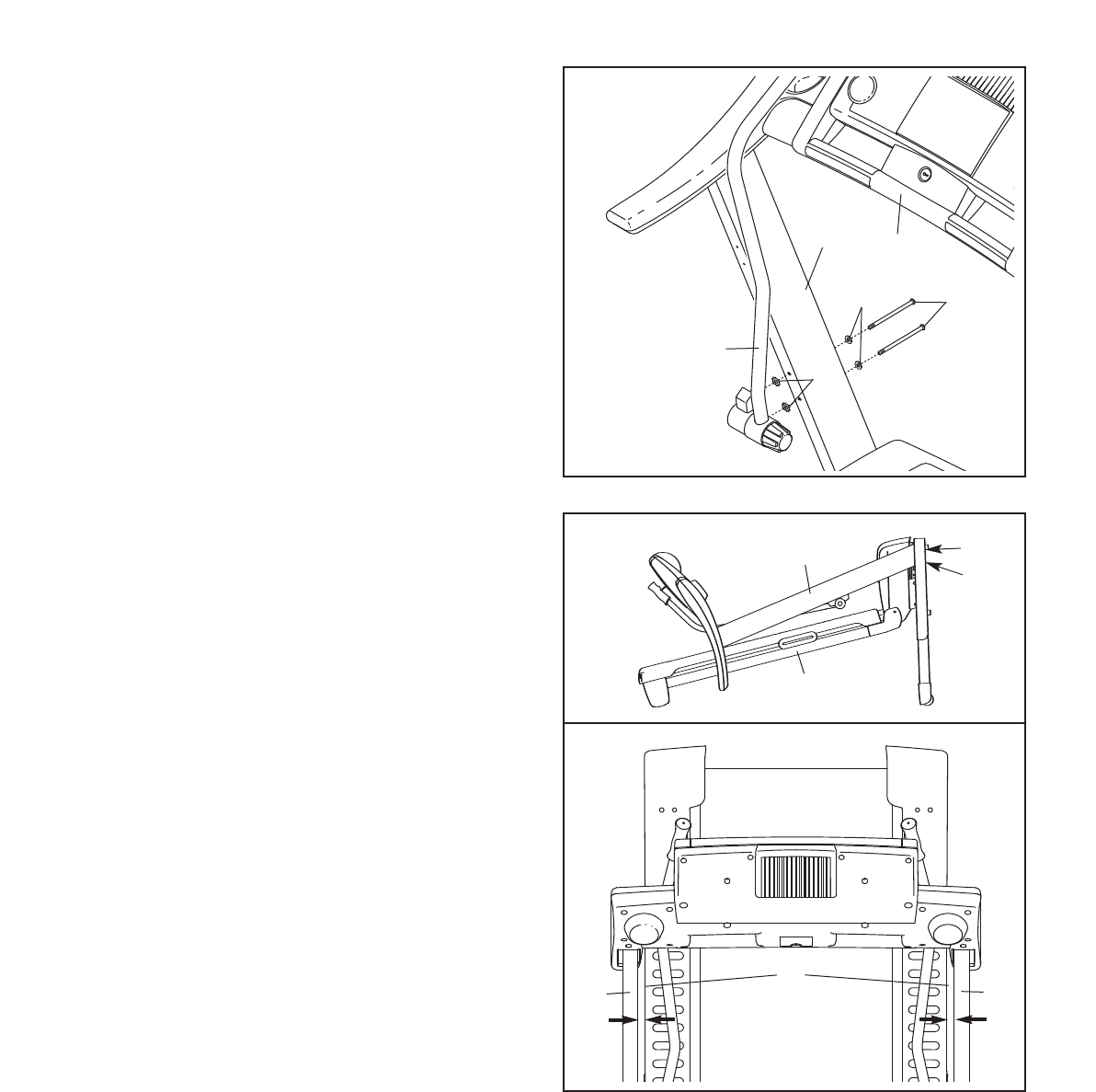
9. With the help of a second person, carefully
lower the Left and Right Uprights (84, 107) to
the position shown.
See the lower drawing. Position the Uprights
(84, 107) so that the treadmill Frame (58) is
centered between the Uprights.
Firmly tighten the two 1" Upright Bolts (106) and
the two 2 3/4" Upright Bolts (105). Be careful
not to overtighten the Upright Bolts.
With the help of a second person, carefully raise
the Uprights (84, 107).
9
58
105
106
84, 107
84
58
107
Top View
8. Attach the Left Upper Body Arm (97) to the Left
Upright (84) with two 4 1/2" Bolts (103), two Flat
Washers (102), and two 3/8" Star Washers (23)
as shown. Make sure that the Left Upper
Body Arm is on the indicated side of the
Console (34).
Attach the Right Upper Body Arm (not shown) to
the Right Upright (not shown) in the same way.
8
34
97
102 103
23
84
10
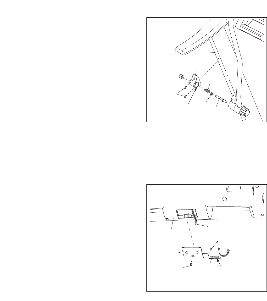
1. Remove the key from the console and unplug
the power cord.
Remove the indicated Screw (3) and the Access
Door (76) from the back of the Console Base (85).
2. Connect the wire on the receiver (A) to the indi-
cated wire extending from the Console Base
(85). Hold the receiver so the small cylinder is
oriented as shown and is facing the Console
Base. Attach the receiver to the plastic posts on
the Access Door (76) with the two included small
screws.
3. Make sure that no wires are pinched. Reattach
the Access Door (76) with the Screw (3). Discard
the other wires included with the receiver.
If you purchase the optional chest pulse sensor (see page 21), follow the steps below to install the receiver
included with the chest pulse sensor.
A
85
Small
Cylinder
3
76
Wire
Small
Screws
10. Attach the Latch Housing (73) to the Left Upright
(84) with two Screws (3); start both Screws
and then tighten them. Note: Make sure that
the large hole in the Latch Housing is on the
indicated side.
Remove the knob from the pin. Make sure that
the collar and the spring are on the pin. (Note: If
there are two collars, place one on each side of
the spring.) Next, insert the pin into the Latch
Housing (73). Then, tighten the knob onto the
pin.
10
3
Pin
Spring
Collar
Knob
73
11. Make sure that all parts are properly tightened before you use the treadmill. If there are sheets of clear
plastic on the treadmill decals, remove the plastic. To protect the floor or carpet, place a mat under the tread-
mill. Note: Extra hardware may be included. Keep the included hex key in a secure place; the large hex key is
used to adjust the walking belt (see page 26).
84
Large Hole
OPERATION AND ADJUSTMENT
THE PRE-LUBRICATED WALKING BELT
Your treadmill features a walking belt coated with high-
performance lubricant. IMPORTANT: Never apply sil-
icone spray or other substances to the walking
belt or the walking platform. Such substances will
deteriorate the walking belt and cause excessive
wear.
HOW TO PLUG IN THE POWER CORD
Your treadmill, like any other type of sophisticated
electronic equipment, can be seriously damaged by
sudden voltage changes in your home’s power.
Voltage surges, spikes, and noise interference can
result from weather conditions or from other appliances
being turned on or off. To decrease the possibility of
your treadmill being damaged, always use a surge
suppressor with your treadmill (see drawing 1 at
the right). To purchase a surge suppressor, see
your local GOLD’S GYM dealer or call the toll-free
telephone number on the front cover of this man-
ual and order part number 146148, or see your local
electronics store.
Use only a single-outlet surge suppressor that is
UL 1449 listed as a transient voltage surge sup-
pressor (TVSS). The surge suppressor must have a
UL suppressed voltage rating of 400 volts or less
and a minimum surge dissipation of 450 joules.
The surge suppressor must be electrically rated for
120 volts AC and 15 amps. There must be a moni-
toring light on the surge suppressor to indicate
whether it is functioning properly. Failure to use a
properly functioning surge suppressor could result
in damage to the control system of the treadmill. If
the control system is damaged, the walking belt
may change speed, accelerate or stop unexpect-
edly, which may result in a fall and serious injury.
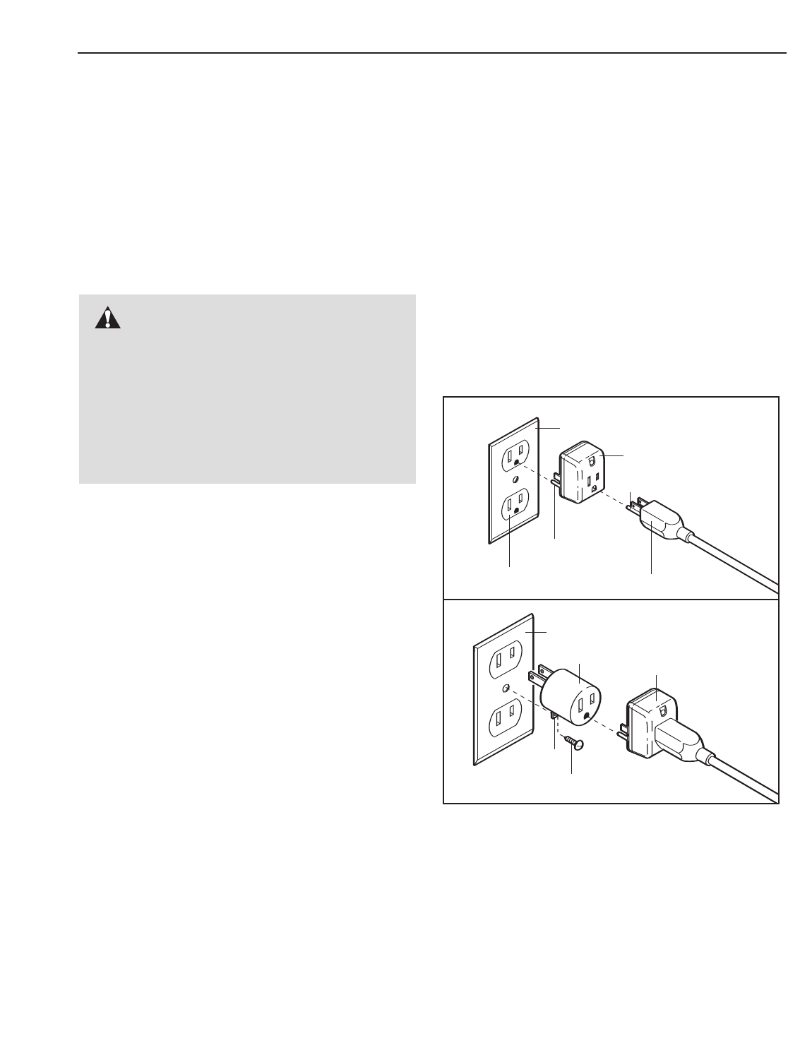
This product must be grounded. If it should malfunc-
tion or break down, grounding provides a path of least
resistance for electric current to reduce the risk of elec-
tric shock. This product is equipped with a cord having
an equipment-grounding conductor and a grounding
plug. Plug the power cord into a surge suppressor,
and plug the surge suppressor into an appropriate
outlet that is properly installed and grounded in
accordance with all local codes and ordinances.
Important: The treadmill is not compatible with
GFCI-equipped outlets.
This product is for use on a nominal 120-volt circuit,
and has a grounding plug that looks like the plug illus-
trated in drawing 1 below. A temporary adapter that
looks like the adapter illustrated in drawing 2 may be
used to connect the surge suppressor to a 2-pole
receptacle as shown in drawing 2 if a properly
grounded outlet is not available.
The temporary adapter should be used only until a
properly grounded outlet (drawing 1) can be installed
by a qualified electrician.
The green-colored rigid ear, lug, or the like extending
from the adapter must be connected to a permanent
ground such as a properly grounded outlet box cover.
Whenever the adapter is used it must be held in place
by a metal screw. Some 2-pole receptacle outlet box
covers are not grounded. Contact a qualified elec-
trician to determine if the outlet box cover is
grounded before using an adapter.
DANGER: Improper connection
of the equipment-grounding conductor can
result in an increased risk of electric shock.
Check with a qualified electrician or service-
man if you are in doubt as to whether the
product is properly grounded. Do not modify
the plug provided with the product—if it will
not fit the outlet, have a proper outlet
installed by a qualified electrician.
1
2
Grounded Outlet Box
Grounded Outlet Box
Grounding Plug
Surge Suppressor
Surge Suppressor
Grounding Pin
Adapter
Lug
Metal Screw
Grounded Outlet
Grounding Pin
11
12
ETGG59606
(GGTL59606)
FEATURES OF THE CONSOLE
The treadmill console offers an impressive array of
features designed to make your workouts more
effective and enjoyable.
When you select the manual mode of the console, you
can change the speed and incline of the treadmill with
the touch of a button. As you exercise, the console will
display continuous exercise feedback. You can even
measure your heart rate using the built-in handgrip
pulse sensor or the optional chest pulse sensor (see
page 21).
The console also features six interactive cross trainer
programs designed to help you to burn calories and
enhance your cardiovascular system while toning and
strengthening your muscles. These programs feature
the voice of a personal trainer to guide you through
your workouts. The cross trainer programs automati-
cally control the speed and incline of the treadmill and
prompt you to perform a variety of strength exercises
during your workout. There are two whole body, two
upper body, and two lower body cross trainer pro-
grams to choose among. Note: The strength exercises
require the use of dumbbells and an inflatable exercise
ball (not included). To purchase dumbbells or an ex-
ercise ball, call the toll-free telephone number on
the front cover of this manual.
A5K program that counts down the distance as you
complete a 5-kilometer run is also included.
The console also offers four calorie programs that con-
trol the speed and incline of the treadmill to help you
burn unwanted pounds.
In addition, the console features a performance pro-
gram. This program automatically controls the speed
and incline of the treadmill as it guides you through an
effective workout.
To use the manual mode of the console, follow the
steps beginning on page 13. To use a cross trainer
program,see page 15. To use the 5K program,see
page 17. To use a calorie program,see page 18. To
use the performance program,see page 19.
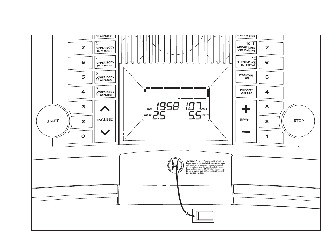
Clip Handgrip Pulse Sensor
CONSOLE DIAGRAM
Key
Note: If there is a sheet of clear plastic
on the face of the console, remove it.
13
HOW TO TURN ON THE POWER
Plug in the power cord
(see page 11). Next, lo-
cate the reset/off circuit
breaker near the power
cord. Make sure that the
circuit breaker is in the
reset position.
Stand on the foot rails of the treadmill. Find the clip at-
tached to the key (see the drawing on page 12), and
slide the clip onto the waistband of your clothes. Next,
insert the key into the console. The display will light.
Important: In an emergency situation, the key can
be pulled from the console, causing the walking
belt to slow to a stop. Test the clip by carefully tak-
ing a few steps backward; if the key is not pulled
from the console, adjust the position of the clip.
The first time the treadmill is used, observe the align-
ment of the walking belt, and align the walking belt if
necessary (see page 26). Note: To prevent damage
to the walking platform, always wear clean shoes
while using the treadmill.
HOW TO USE THE MANUAL MODE
Insert the key into the console.
See HOW TO TURN ON THE POWER above.
Select the manual mode.
When the
key is in-
serted, the
manual
mode will be
selected. If
you have
selected a program, reselect the manual mode by
pressing any of the cross trainer buttons once or
twice until a track appears in the display.
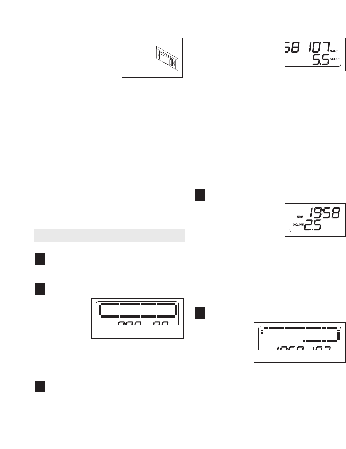
Start the walking belt.
To start the walking belt, press the Start button,
the Speed + button, or one of the speed buttons
numbered 1 to 10.
If the Start button or the Speed + button is
pressed, the walking belt will begin to move at 1
mph. As you exercise, change the speed of the
walking belt as desired by pressing the Speed +
and – buttons. Each
time a button is pressed,
the speed setting will
change by 0.1 mph; if a
button is held down, the
speed setting will
change in increments of
0.5 mph. Note: After the buttons are pressed, it may
take a moment for the walking belt to reach the se-
lected speed setting.
If one of the numbered speed buttons is pressed,
the walking belt will gradually change speed until it
reaches the selected speed setting.
To stop the walking belt, press the Stop button.
The time will begin to flash in the display. To
restart the walking belt, press the Start button, the
Speed + button, or one of the numbered speed but-
tons.
Change the incline of the treadmill as desired.
To change the incline of
the treadmill, press the
Incline increase and de-
crease buttons or one of
the incline buttons num-
bered 0 to 10. Each time
the Incline increase or decrease button is
pressed, the incline will change by 0.5%. If one of
the numbered incline buttons is pressed, the
treadmill will adjust to the selected incline setting.
Note: After the buttons are pressed, it may take a
moment for the treadmill to reach the selected in-
cline setting.
Follow your progress with the display.
When the
manual mode
or the 5K
program is
selected, the
display will
show a track
that represents 1/4 mile. As you walk or run, indi-
cators will appear in succession around the track
until the entire track appears. The track will then
disappear and the indicators will again begin to ap-
pear in succession.
5
4
3
2
1
Track
Reset
Position
Track
14
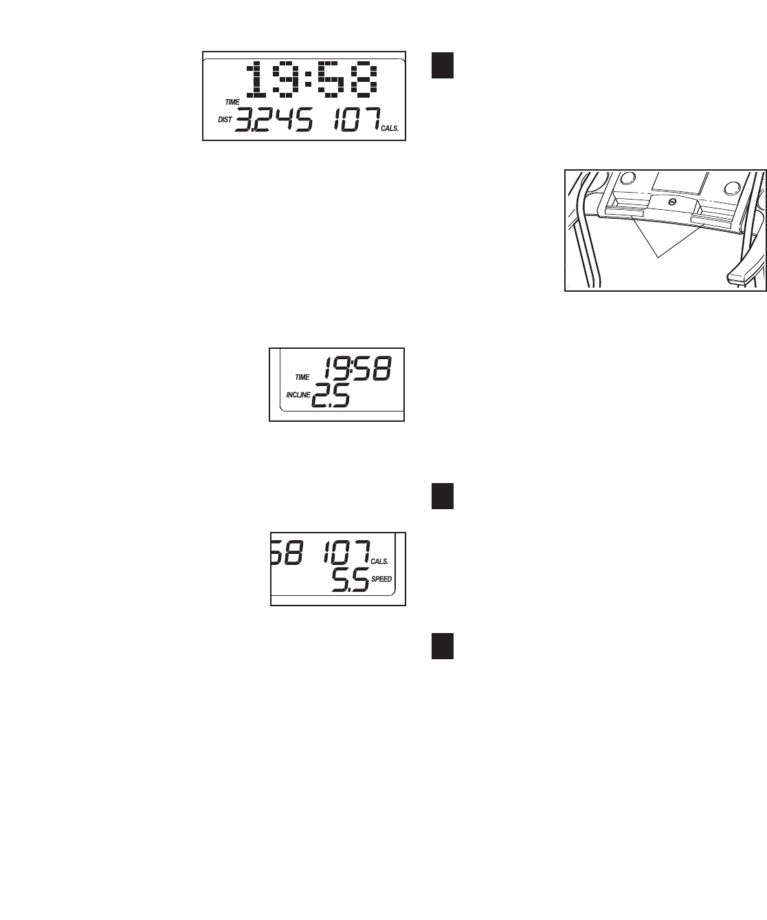
The upper
part of the
display can
also show
the elapsed
time, the
distance that
you have walked or run, the speed of the walking
belt, the approximate number of calories you have
burned while walking or running, your pace in min-
utes per mile, or the incline level of the treadmill. If
desired, press the Display button repeatedly until
the upper part of the display shows the information
you are most interested in viewing. Note: While in-
formation is shown in the upper part of the display,
the same information will not be shown in the
lower parts of the display.
The left side of the dis-
play will show the
elapsed time, the dis-
tance that you have
walked or run, and the
incline level of the tread-
mill. Note: When a program is selected (except for
the 5K program), the display will show the time re-
maining in the program instead of the elapsed
time.
The right side of the
display will show the
approximate number of
calories you have
burned while walking or
running, the speed of
the walking belt, and your pace in minutes per
mile. The right side of the display will also show
your heart rate when you use the handgrip pulse
sensor or the optional chest pulse sensor.
Note: The console can display speed and dis-
tance in either miles or kilometers. To find out
which unit of measurement is selected or to
change the unit of measurement, see THE IN-
FORMATION MODE on page 21. Note: For sim-
plicity, all instructions in this section refer to
miles.
To reset the display, press the Stop button, re-
move the key, and then reinsert the key.
Measure your heart rate if desired.
Note: If you use the handgrip pulse sensor and
the optional chest pulse sensor at the same
time, the console will not display your heart
rate accurately.
Before using
the handgrip
pulse sen-
sor, remove
the sheets of
clear plastic
from the
metal con-
tacts. In ad-
dition, make sure that your hands are clean. To
measure your heart rate, stand on the foot rails
and hold the metal contacts on the handrail—
avoid moving your hands.When your pulse is
detected, one or two dashes will appear in the
right side of the display and then your heart rate
will be shown. For the most accurate heart rate
reading, continue to hold the contacts for
about 15 seconds.
Turn on the fan if desired.
To turn on the fan at high speed, press the Fan
button. To turn on the fan at low speed, press the
button a second time. To turn off the fan, press
the button a third time. Note: If the fan is on when
the walking belt stops, the fan will automatically
turn off after a few minutes.
When you are finished exercising, remove the
key from the console.
Step onto the foot rails, press the Stop button, and
adjust the incline of the treadmill to the lowest
setting. The incline must be at the lowest setting
when the treadmill is folded to the storage posi-
tion or the treadmill will be damaged. Next, re-
move the key from the console and put it in a se-
cure place. Note: If the display remains lit after
the key is removed, the console is in the
“demo” mode. See page 21 and turn off the
demo mode.
When you are finished using the treadmill,
switch the reset/off circuit breaker to the “off”
position and unplug the power cord.
8
7
6
Contacts
15
HOW TO USE A CROSS TRAINER PROGRAM
Insert the key into the console.
See HOW TO TURN ON THE POWER on page
13.
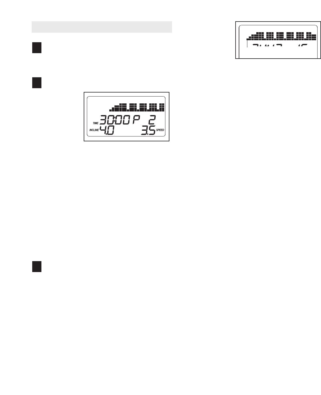
Select one of the six cross trainer programs.
To select a
cross trainer
program,
press one of
the Whole
Body but-
tons, the
Upper Body
buttons, or
the Lower Body buttons; “P 1,” “P 2,” “P 3,” “P 4,”
“P 5,” or “P 6” will appear in the display. When a
cross trainer program is selected, the program
time will appear in the display every few seconds,
the maximum incline setting of the program and
the maximum speed setting of the program will
flash in the display for a few seconds, and a pro-
file of the speed settings of the program will scroll
across the matrix in the display.
Note: During the program, a personal trainer will
guide you through the workout. You can adjust the
volume or select an audio setting for your personal
trainer (see THE INFORMATION MODE on page
21).
Press the Start button to start the program.
Amoment after the button is pressed, the tread-
mill will automatically adjust to the first speed and
incline settings of the program. Hold the handrails
and begin walking.
Each program is divided into 30 or 45 one-minute
segments. One speed setting and one incline set-
ting are programmed for most segments. (Note:
The same speed setting and/or incline setting may
be programmed for two or more consecutive seg-
ments.) During other segments, the console will
prompt you to perform strength exercises.
The speed
setting for
the first seg-
ment will be
shown in the
flashing
Current
Segment column of the matrix. (The incline set-
tings are not shown in the matrix.) The speed set-
tings for the next several segments will be shown
in the columns to the right.
When only three seconds remain in the first seg-
ment of the program, both the Current Segment
column and the column to the right will flash. If the
speed and/or incline of the treadmill is about to
change, the personal trainer will alert you, and the
speed setting and/or the incline setting will flash in
the display.
When the first segment is completed,
all speed
settings will move one column to the left
.The
speed setting for the second segment will then be
shown in the flashing Current Segment column
and the treadmill will automatically adjust to the
speed and incline settings for the second seg-
ment. Note: If all of the indicators in the Current
Segment column are lit,
the speed settings may
move downward
so that only the highest indicators
appear in the matrix.
If the speed or incline setting for the current seg-
ment is too high or too low, you can manually
override the setting by pressing the Speed and
Incline buttons. Every few times a Speed button is
pressed, an additional indicator will appear or dis-
appear in the Current Segment column; if any of
the columns to the right of the Current Segment
column have the same number of lit indicators as
the Current Segment column, an additional indica-
tor may appear or disappear in those columns as
well. Important: When the current segment of
the program ends, the treadmill will automati-
cally adjust to the speed and incline settings
for the next segment.
To stop the program at any time, press the Stop
button. The time will begin to flash in the display.
To restart the program, press the Start button or
the Speed + button. The walking belt will begin to
move at 1 mph. When the next segment of the pro-
gram begins, the treadmill will automatically adjust
to the speed and incline settings for that segment.
3
2
1Current Segment
16
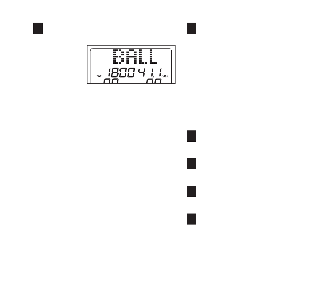
Perform the first strength exercise when
prompted.
When the
first strength
exercise
segment be-
gins (only
one indica-
tor will flash
in the Current Segment column), the walking belt
will slow to a stop and the name of the first
strength exercise will appear in the display for a
few seconds.
Next, the personal trainer will tell you the recom-
mended number of repetitions for the first strength
exercise.
Remove the clip from the waistband of your
clothes, step off the treadmill, and prepare to
begin the first strength exercise. The personal
trainer and the display will count the repetitions;
perform one repetition of the exercise on each
count. Exercise with a slow, steady motion; do not
perform more than one repetition for each count.
Note: Refer to the accompanying exercise chart to
see the correct form for each exercise. When per-
forming lunges, alternate legs with each repetition.
When performing dumbbell rows, perform half the
repetitions with your right arm and half the repeti-
tions with your left arm. The strength exercises re-
quire the use of dumbbells and an inflatable exer-
cise ball (not included). To purchase dumbbells
or an exercise ball, call the toll-free telephone
number on the front cover of this manual.
Continue the cross trainer program.
When you have performed the recommended
number of repetitions, the words PRESS START
will appear in the display. To continue the cross
trainer program, step onto the treadmill, slide the
clip back onto the waistband of your clothes,
and press the Start button. The treadmill will auto-
matically adjust to the speed and incline settings
for the next segment.
The program will continue in this way until the last
segment ends. The walking belt will then slow to a
stop.
Follow your progress with the display.
See step 5 on pages 13 and 14.
Measure your heart rate if desired.
See step 6 on page 14.
Turn on the fan if desired.
See step 7 on page 14.
When you are finished exercising, remove the
key from the console.
See step 8 on page 14.
9
8
7
6
54
17
HOW TO USE THE 5K PROGRAM
Insert the key into the console.
See HOW TO TURN ON THE POWER on page
13.
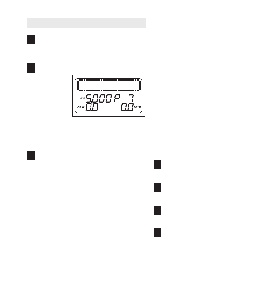
Select the 5K program.
To select
the 5K pro-
gram, press
the 5K Race
button; “P 7”
will appear
in the dis-
play. A dis-
tance goal
of 5 kilometers will also appear in the display
every few seconds and a track will appear in the
matrix.
Press the Start button to start the program.
Amoment after the button is pressed, the walking
belt will begin to move at 3 mph. Hold the
handrails and begin walking.
Near the end of the second minute of the pro-
gram, the speed setting will flash in the display
and a series of tones will sound. The speed of the
walking belt will then increase to 4 mph.
Near the end of the fourth minute of the program,
the speed setting will flash in the display and a se-
ries of tones will sound. The speed of the walking
belt will then increase to 5 mph.
Near the end of the fifth minute of the program,
the speed setting will flash in the display and a se-
ries of tones will sound. The speed of the walking
belt will then increase to 6.5 mph.
Note: To change the speed of the walking belt or
the incline of the treadmill at any time during the
program, press the Speed or Incline buttons.
The upper left corner of the display will show the
number of meters still to be run. When only 20
meters remain, the display will flash and a series
of tones will sound.
To stop the program at any time, press the Stop
button. The time will begin to flash in the display.
To restart the program, press the Start button. The
walking belt will begin to move at 1 mph. Adjust
the speed of the walking belt as desired by press-
ing the Speed + or – button or one of the ten num-
bered speed buttons.
When you have completed a 5-kilometer run, your
total time will flash in the lower left corner of the
display and the words “cool” and “down” (cool
down) will flash in the upper left corner of the dis-
play. If the speed of the walking belt is greater
than 5 mph, the walking belt will then slow to 5
mph for one minute. After one minute, the walking
belt will slow to 4 mph for 2 minutes. The walking
belt will then slow to 3 mph for 2 minutes. The
walking belt will then slow to a stop.
Follow your progress with the display.
See step 5 on pages 13 and 14.
Measure your heart rate if desired.
See step 6 on page 14.
Turn on the fan if desired.
See step 7 on page 14.
When you are finished exercising, remove the
key from the console.
See step 8 on page 14.
7
6
5
4
3
2
1
18
HOW TO USE A CALORIE PROGRAM
Insert the key into the console.
See HOW TO TURN ON THE POWER on page
13.
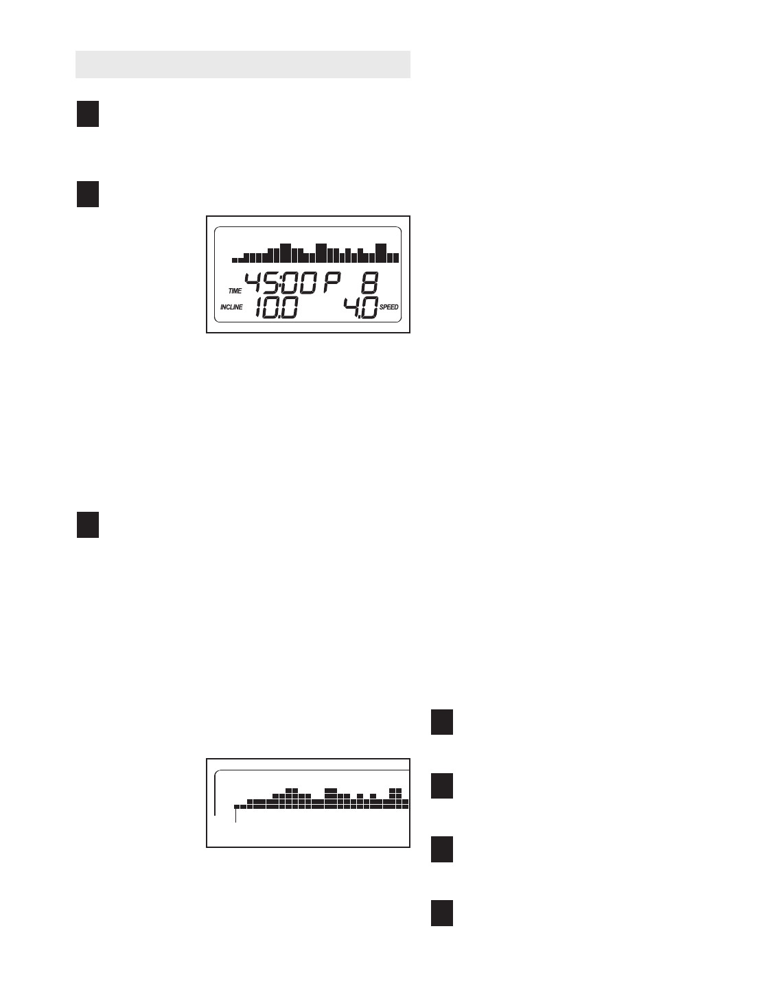
Select a calorie program.
To select a
calorie pro-
gram, press
one of the
Weight Loss
buttons once
or twice;
“P 8,” “P 9,”
“P10,” or
“P11” will appear in the display. When a calorie
program is selected, the maximum speed setting
of the program and the maximum incline setting of
the program will flash in the display for a few sec-
onds; in addition, the display will show how long
the program will last every few seconds. A profile
of the speed settings of the program will scroll
across the matrix in the display.
Press the Start button or the Speed increase
button to start the program.
Amoment after the button is pressed, the tread-
mill will automatically adjust to the first speed and
incline settings for the program. Hold the handrails
and begin walking.
Each program is divided into several one-minute
segments. One speed setting and one incline set-
ting are programmed for each segment. Note: The
same speed setting and/or incline setting may be
programmed for two or more consecutive seg-
ments.
The speed
setting for
the first seg-
ment will be
shown in the
flashing
Current
Segment column of the matrix. (The incline set-
tings are not shown in the matrix.) The speed set-
tings for the next several segmentswill be shown
in the columns to the right.
When only three seconds remain in the first seg-
ment of the program, both the Current Segment
column and the column to the right will flash and a
series of tones will sound. If the speed and/or in-
cline of the treadmill is about to change, the speed
setting and/or the incline setting will flash in the
display to alert you.
When the first segment is completed,
all speed
settings will move one column to the left
.The
speed setting for the second segment will then be
shown in the flashing Current Segment column
and the treadmill will automatically adjust to the
speed and incline settings for the second seg-
ment. Note: If all of the indicators in the Current
Segment column are lit, the speed settings may
move downward so that only the highest indicators
appear in the matrix.
The program will continue in this way until the
speed setting for the last segment is shown in the
Current Segment column and the last segment
ends. The walking belt will then slow to a stop.
If the speed or incline setting for the current
segment is too high or too low, you can manually
override the setting by pressing the Speed or
Incline buttons. Note: If you change the speed or
incline of the walking belt, you may not reach your
calorie goal. Important: When the current seg-
ment of the program ends, the treadmill will au-
tomatically adjust to the speed and incline set-
tings for the next segment.
To stop the program at any time, press the Stop
button. To restart the program, press the Start but-
ton or the Speed + button. The walking belt will
begin to move at 1 mph. When the next segment
of the program begins, the treadmill will automati-
cally adjust to the speed and incline settings for the
next segment.
Follow your progress with the display.
See step 5 on pages 13 and 14.
Measure your heart rate if desired.
See step 6 on page 14.
Turn on the fan if desired.
See step 7 on page 14.
When you are finished exercising, remove the
key from the console.
See step 8 on page 14.
7
6
5
4
3
2
1
Current Segment
19
HOW TO USE THE PERFORMANCE PROGRAM
Insert the key into the console.
See HOW TO TURN ON THE POWER on page
13.
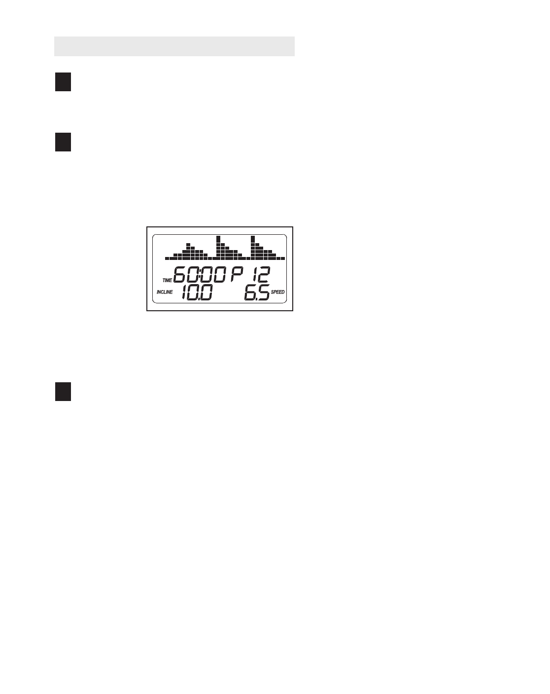
Select the performance program.
To select the performance program, press the
Performance button; “P12” will appear in the dis-
play. A few seconds after the performance pro-
gram is selected, the maximum speed setting of
the program and the maximum incline setting of
the program
will flash in
the display
for a few
seconds; in
addition, the
display will
show how
long the pro-
gram will last
every few seconds. A profile of the speed settings
of the program will scroll across the matrix in the
display.
Press the Start button to start the program.
Amoment after the button is pressed, the tread-
mill will automatically adjust to the first speed and
incline settings for the program. Hold the handrails
and begin walking.
The program is divided into 60 one-minute seg-
ments. One speed setting and one incline setting
are programmed for each segment. Note: The
same speed setting and/or incline setting may be
programmed for two or more consecutive seg-
ments.
The speed setting for the first segment will be
shown in the flashing Current Segment column of
the matrix. (The incline settings are not shown in
the matrix.) The speed settings for the next sev-
eral segments will be shown in the columns to the
right.
When only three seconds remain in the first seg-
ment of the program, both the Current Segment
column and the column to the right will flash and a
series of tones will sound. If the speed and/or in-
cline of the treadmill is about to change, the speed
setting and/or the incline setting will flash in the
display to alert you.
When the first segment is completed,
all speed
settings will move one column to the left
.The
speed setting for the second segment will then be
shown in the flashing Current Segment column
and the treadmill will automatically adjust to the
speed and incline settings for the second seg-
ment. Note: If all of the indicators in the Current
Segment column are lit, the speed settings may
move downward so that only the highest indicators
appear in the matrix.
The program will continue in this way until the
speed setting for the last segment is shown in the
Current Segment column and the last segment
ends. The walking belt will then slow to a stop.
If the speed or incline setting for the current
segment is too high or too low, you can manually
override the setting by pressing the Speed or
Incline buttons. Every few times a Speed button is
pressed, an additional indicator will appear or dis-
appear in the Current Segment column; if any of
the columns to the right of the Current Segment
column have the same number of lit indicators as
the Current Segment column, an additional indica-
tor may appear or disappear in those columns as
well.
3
2
1

20
Important: When the current segment of the
program ends, the treadmill will automatically
adjust to the speed and incline settings for the
next segment.
To stop the program at any time, press the Stop
button. To restart the program, press the Start but-
ton or the Speed + button. The walking belt will
begin to move at 1 mph. When the next segment
of the program begins, the treadmill will automati-
cally adjust to the speed and incline settings for
that segment.
Follow your progress with the display.
See step 5 on pages 13 and 14.
Measure your heart rate if desired.
See step 6 on page 14.
Turn on the fan if desired.
See step 7 on page 14.
When you are finished exercising, remove the
key from the console.
See step 8 on page 14.
7
6
5
4
21
THE INFORMATION MODE
The console features an information mode that keeps
track of treadmill usage information. The information
mode also allows you to select miles or kilometers as
the unit of measurement, to select an audio trainer set-
ting, and to turn on and turn off the demo mode.
To select the information mode, hold down the Stop
button, insert the key into the console, and then release
the Stop button. When the information mode is se-
lected, the following information will appear in the dis-
play:
The center of
the display will
show the total
number of hours
that the tread-
mill has been
operated. The
lower part of the
display will
show total number of miles or kilometers that the walk-
ing belt has moved. In addition, an “E” for English miles
or an “M” for metric kilometers will appear in the lower
part of the display. To change the unit of measurement,
press the Speed + button.
The upper left part of the
display will show the per-
sonal trainer audio setting.
If you select “ON” as the
audio setting, the personal
trainer will guide you
through your workouts and
give detailed instructions. If you select the “OFF” set-
ting, your personal trainer will simply guide you
through your workouts. Press the Incline decrease but-
ton to change the audio setting if desired.
You can adjust the volume
of the personal trainer
audio (0 through 5) by
pressing the Incline in-
crease button repeatedly.
The volume setting ap-
pears as the upper right digit in the display.
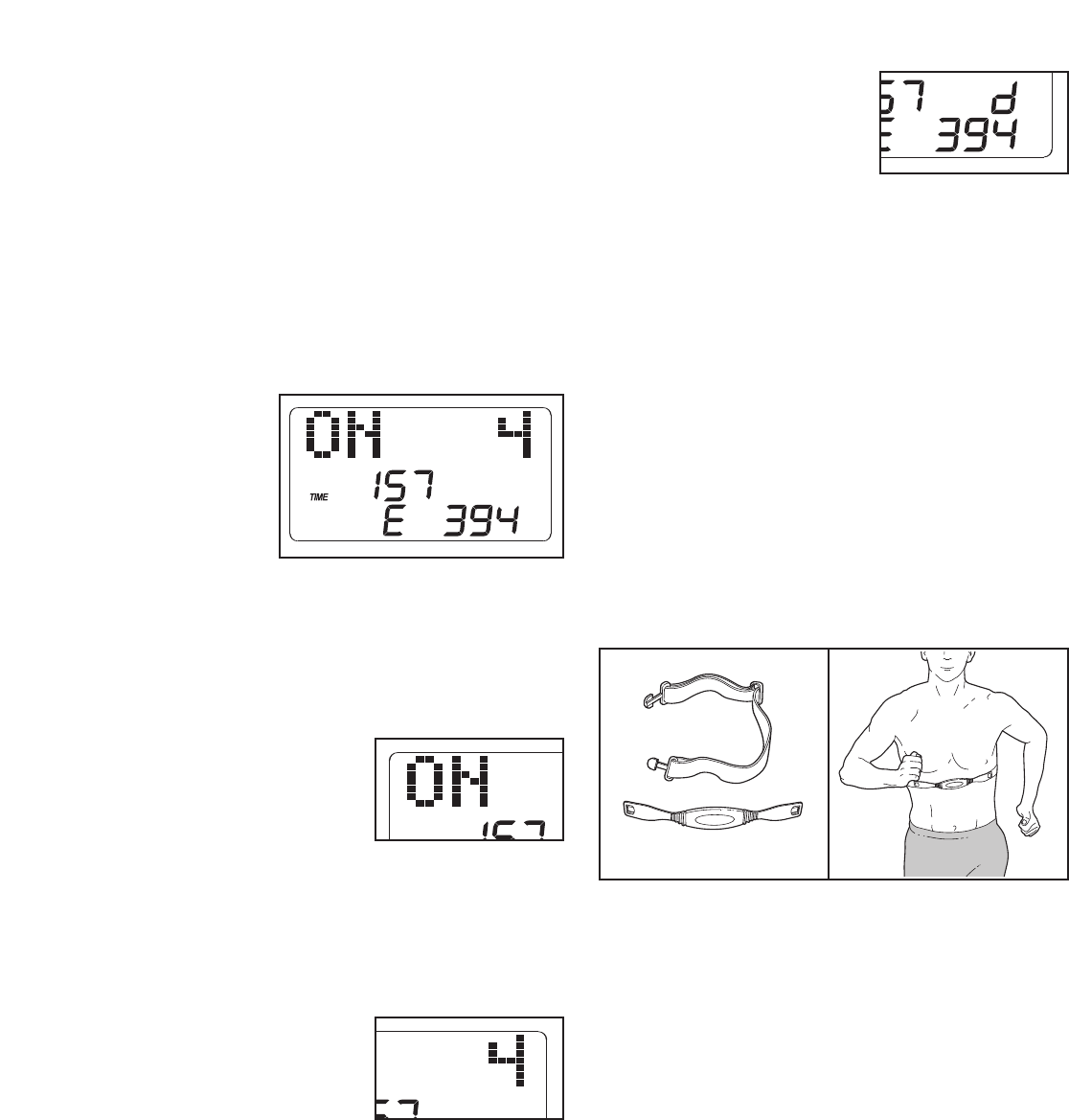
IMPORTANT: If a “d” ap-
pears in the display, the con-
sole is in the “demo” mode.
This mode is intended to be
used only when a treadmill is
displayed in a store. When
the console is in the demo mode, the power cord can
be plugged in, the key can be removed from the con-
sole, and the indicators in the display will automatically
appear in a preset sequence; the buttons on the con-
sole will not operate. If a “d” appears when the infor-
mation mode is selected, press the Speed – button
so the “d” disappears.
To exit the information mode, remove the key from the
console.
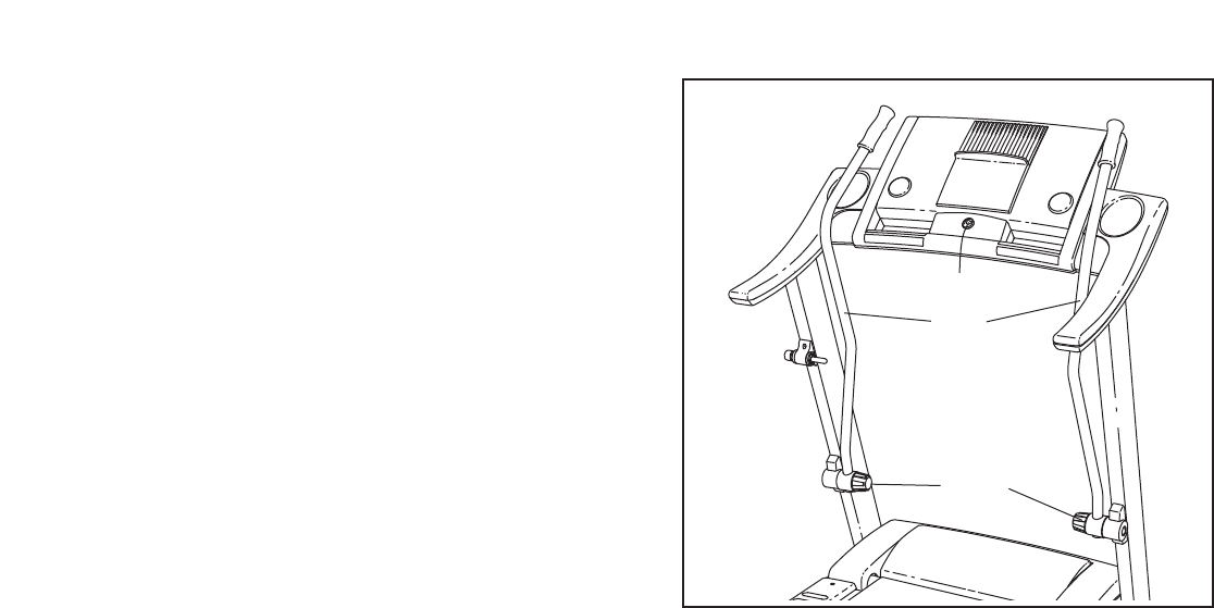
THE OPTIONAL CHEST PULSE SENSOR
An optional chest pulse sensor offers hands-free oper-
ation as it tracks your heart rate during your workouts.
To purchase the optional chest pulse sensor, call
the toll-free telephone number on the front cover
of this manual.
22
HOW TO USE THE UPPER BODY ARMS
Asyou walk on the treadmill, you can hold the
handrails or use the upper body arms. To exercise
your arms, shoulders, and back for a total body work-
out, move the upper body arms forward and back as
you walk on the treadmill.
Tovary the intensity of your upper body exercise, the
resistance of the upper body arms can be adjusted. To
increase the resistance, turn the resistance knobs
clockwise; to decrease the resistance, turn the knobs
counterclockwise.
Upper Body
Arms
Resistance
Knobs
23
HOW TO FOLD AND MOVE THE TREADMILL
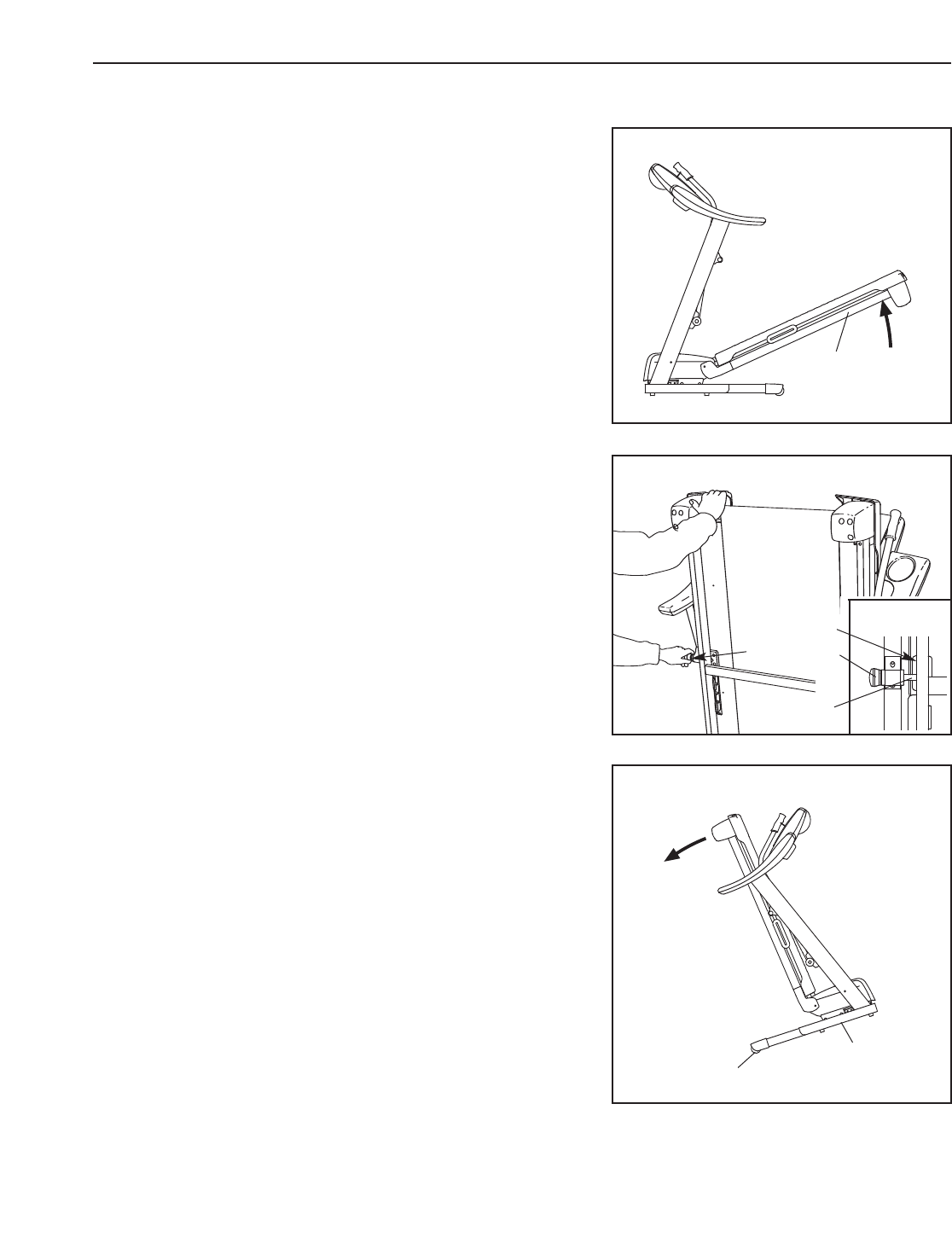
HOW TO FOLD THE TREADMILL FOR STORAGE
Before folding the treadmill, adjust the incline to the
lowest position. If you do not do this, you may damage the
treadmill when you fold it. Next, unplug the power cord.
CAUTION: You must be able to safely lift 45 pounds (20 kg)
to raise, lower, or move the treadmill.
1. Hold the metal frame firmly in the location shown by the
arrow at the right. CAUTION: To decrease the possibility
of injury, do not lift the treadmill by the plastic foot rails.
Make sure to bend your legs and keep your back straight
as you raise the frame. Raise the frame about halfway to the
vertical position.
2. Move your right hand to the position shown and hold the
treadmill firmly. Using your left hand, pull the latch knob to
the left and hold it. Raise the frame until the catch is past the
latch pin. Slowly release the latch knob. Make sure that the
catch is resting against the latch pin.
To protect the floor or carpet from damage, place a mat
under the treadmill. Keep the treadmill out of direct sun-
light. Do not leave the treadmill in the storage position in
temperatures above 85° F (30°C).
HOW TO MOVE THE TREADMILL
Before moving the treadmill, convert the treadmill to the storage
position as described above. Make sure that the catch is rest-
ing against the latch pin.
1. Hold the upper ends of the handrails. Place one foot against
one of the wheels.
2. Tilt the treadmill back until it rolls freely on the front wheels.
Carefully move the treadmill to the desired location. To re-
duce the risk of injury, use extreme caution while mov-
ing the treadmill. Do not move the treadmill over an un-
even surface.
3. Place one foot against one of the wheels, and carefully lower
the treadmill until it is resting in the storage position.
Engaged
Catch
Latch Knob
Latch Pin
Base
Wheel
Frame
24
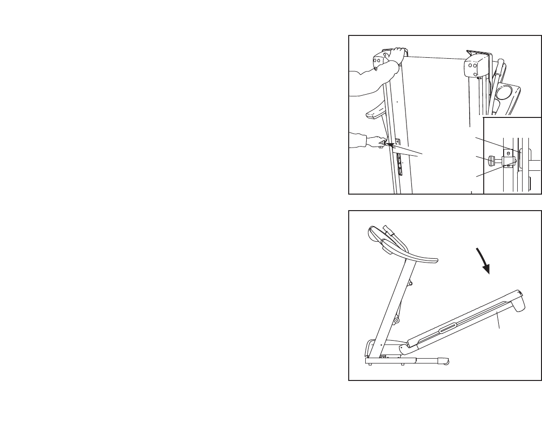
HOW TO LOWER THE TREADMILL FOR USE
1. Hold the upper end of the treadmill with your right hand. Pull
the latch knob to the left and hold it. Pivot the frame down
until the catch is past the latch pin.
2. Hold the metal frame firmly with both hands,and lower it to
the floor. CAUTION: To decrease the possibility of injury, do
not lower the frame by gripping only the plastic foot rails.
Do not drop the frame to the floor. Make sure to bend your
legs and keep your back straight.
Open
Catch
Latch Pin
Frame
Latch Knob
25
TROUBLESHOOTING
Most treadmill problems can be solved by following the steps below. Find the symptom that applies, and
follow the steps listed. If further assistance is needed, please see the front cover of this manual.
PROBLEM: The power does not turn on
SOLUTION: a. Make sure that the power cord is plugged into a surge suppressor, and that the surge suppressor
is plugged into a properly grounded outlet (see page 11). Use only a single-outlet surge suppres-
sor that meets all of the specifications described on page 11. Important: The treadmill is not com-
patible with GFCI-equipped outlets.
b. After the power cord has been plugged in, make sure that the key is inserted into the console.
c. Check the reset/off circuit breaker located on the
treadmill frame near the power cord. If the switch
protrudes as shown, the circuit breaker has
tripped. To reset the circuit breaker, wait for five
minutes, and then press the switch back in.
PROBLEM: The power turns off during use
SOLUTION: a. Check the reset/off circuit breaker (see the drawing above). If the circuit breaker has tripped, wait
for five minutes and then press the switch back in.
b. Make sure that the power cord is plugged in. If the power cord is plugged in, unplug it, wait for
five minutes, and then plug it back in.
c. Remove the key from the console. Reinsert the key into the console.
d. If the treadmill still will not run, see the front cover of this manual.
PROBLEM: The incline of the treadmill does not change correctly
SOLUTION: a. With the key in the console, press one of the Incline buttons. While the incline is changing, re-
move the key. After a few seconds, reinsert the key. The treadmill will automatically rise to the
maximum incline level and then return to the minimum level. This will recalibrate the incline system.
PROBLEM: The display of the console does not function properly
SOLUTION: a. Remove the key from the console and UNPLUG THE
POWER CORD.Next, carefully lower the Uprights
(84). Remove the two indicated 3/4" Screws (2). Note:
Aphillips screwdriver with at least an 8" shaft is
needed.
Tripped Reset
c
2
84
2
a
Raise the Uprights (84) to the vertical position.
Remove the three Hood Screws (7) from the Hood
(41), and carefully pivot the Hood off.
Locate the Reed Switch (63) and the Magnet (46) on
the left side of the Pulley (47). Turn the Pulley until the
Magnet is aligned with the Reed Switch. Make sure
that the gap between the Magnet and the Reed
Switch is about 1/8”. If necessary, loosen the Screw
(33), move the Reed Switch slightly, and then
retighten the Screw. Reattach the Motor Hood (not
shown); make sure that the Hood Screws (not shown)
are inserted into the same holes from which they were
removed. Run the treadmill for a few minutes to check
for a correct speed reading.
PROBLEM: The walking belt slows when walked on
SOLUTION: a. Use only a single-outlet surge suppressor that meets all of the specifications described on page 11.
b. If the walking belt is overtightened, treadmill perfor-
mance may decrease and the walking belt may be-
come damaged. Remove the key and UNPLUG THE
POWER CORD.Using the hex key, turn both rear
roller bolts counterclockwise, 1/4 of a turn. When the
walking belt is properly tightened, you should be able
to lift each edge of the walking belt 3 to 4 inches off
the walking platform. Be careful to keep the walking
belt centered. Then, plug in the power cord, insert the
key, and run the treadmill for a few minutes. Repeat
until the walking belt is properly tightened.
c. If the walking belt still slows when walked on, please see the front cover of this manual.
PROBLEM: The walking belt is off-center or slips when walked on
SOLUTION: a. If the walking belt is off-center, first remove the key
and UNPLUG THE POWER CORD.If the walking
belt has shifted to the left, use the hex key to turn
the left rear roller bolt clockwise 1/2 of aturn; if the
walking belt has shifted to the right, turn the left
bolt counterclockwise 1/2 of a turn. Be careful not to
overtighten the walking belt. Then, plug in the power
cord, insert the key, and run the treadmill for a few
minutes. Repeat until the walking belt is centered.
b. If the walking belt slips when walked on, first re-
move the key and UNPLUG THE POWER CORD.
Using the hex key, turn both rear roller bolts clock-
wise, 1/4 of a turn. When the walking belt is correctly
tightened, you should be able to lift each edge of the
walking belt 3 to 4 inches off the walking platform. Be
careful to keep the walking belt centered. Then, plug
in the power cord, insert the key, and carefully walk
on the treadmill for a few minutes. Repeat until the
walking belt is properly tightened.
b
a
Rear Roller Bolts
3"–4"
b
46
63
Top
View
1/8"
47
33
7
7
84
41
26
27
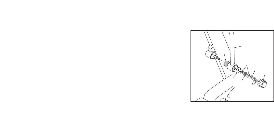
PROBLEM: The upper body arms squeak during use
SOLUTION: a.(Note: Correcting this problem requires a small amount
of white marine grease, available at hardware stores.)
Turn the Resistance Knob (A) counterclockwise and
remove it. Next, remove the Resistance Cone (B) and
the Upper Body Arm (109), along with the Resistance
Plate (C), Washers (D), Spring Washer (E), Thrust
Washers (F), and Thrust Bearing (G). (Note: If the
Resistance Plate [C] comes out of the Resistance
Cone [B], press it back in.) Apply a thin layer of white
marine grease to the outer surface of the Resistance
Cone (B). Then, reattach all parts in the order shown
at the right.
B109
A
F
E
CG
D
28
CONDITIONING GUIDELINES
The following guidelines will help you to plan your ex-
ercise program. For more detailed exercise informa-
tion, obtain a reputable book or consult your physician.
EXERCISE INTENSITY
Whether your goal is to burn fat or to strengthen your
cardiovascular system, the key to achieving the
desired results is to exercise with the proper intensity.
The proper intensity level can be found by using your
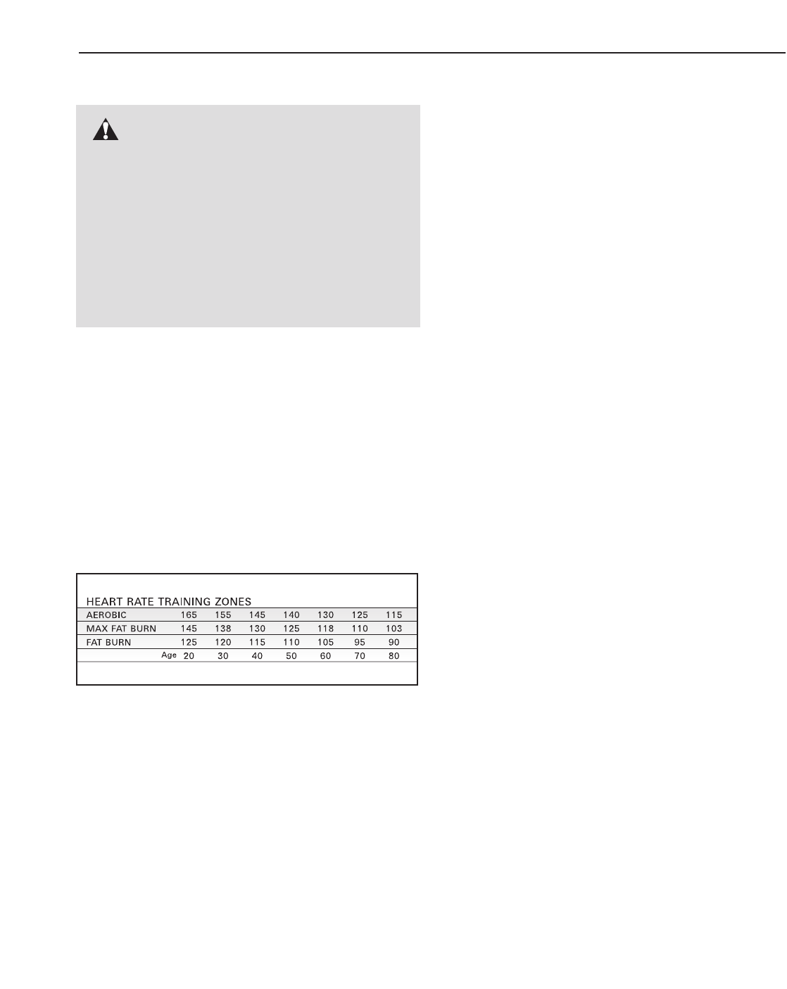
heart rate as a guide. The chart below shows recom-
mended heart rates for fat burning and aerobic exercise.
To find the proper heart rate for you, first find your age
near the bottom of the chart (ages are rounded off to
the nearest ten years). Next, find the three numbers
above your age. The three numbers define your “train-
ing zone.” The lower two numbers are recommended
heart rates for fat burning; the higher number is the
recommended heart rate for aerobic exercise.
Fat Burning
To burn fat effectively, you must exercise at a relatively
low intensity level for a sustained period of time.
During the first few minutes of exercise, your body
uses easily accessible
carbohydrate calories
for en-
ergy. Only after the first few minutes does your body
begin to use stored
fat calories
for energy. If your goal
is to burn fat, adjust the speed and incline of the tread-
mill until your heart rate is near the lowest number in
your training zone.
For maximum fat burning, adjust the speed and incline
of the treadmill until your heart rate is near the middle
number in your training zone.
Aerobic Exercise
If your goal is to strengthen your cardiovascular sys-
tem, your exercise must be “aerobic.” Aerobic exercise
is activity that requires large amounts of oxygen for
prolonged periods of time. This increases the demand
on the heart to pump blood to the muscles, and on the
lungs to oxygenate the blood. For aerobic exercise,
adjust the speed and incline of the treadmill until your
heart rate is near the highest number in your training
zone.
WORKOUT GUIDELINES
Each workout should include the following three parts:
AWarm-up—Start each workout with 5 to 10 minutes
of stretching and light exercise. A proper warm-up in-
creases your body temperature, heart rate and circula-
tion in preparation for exercise.
Training Zone Exercise—After warming up, increase
the intensity of your exercise until your heart rate is in
your training zone for 20 to 60 minutes. (During the
first few weeks of your exercise program, do not keep
your heart rate in your training zone for longer than 20
minutes.) Breathe regularly and deeply as you exer-
cise—never hold your breath.
ACool-down—Finish each workout with 5 to 10 min-
utes of stretching to cool down. This will increase the
flexibility of your muscles and will help prevent post-
exercise problems.
EXERCISE FREQUENCY
To maintain or improve your condition, complete three
workouts each week, with at least one day of rest be-
tween workouts. After a few months, you may com-
plete up to five workouts each week if desired. The key
to success is to make exercise a regular and enjoyable
part of your everyday life.
WARNING: Before beginning this
or any exercise program, consult your physi-
cian. This is especially important for individu-
als over the age of 35 or individuals with pre-
existing health problems.
The pulse sensor is not a medical device.
Various factors, including your movement,
may affect the accuracy of heart rate readings.
The sensor is intended only as an exercise aid
in determining heart rate trends in general.
29
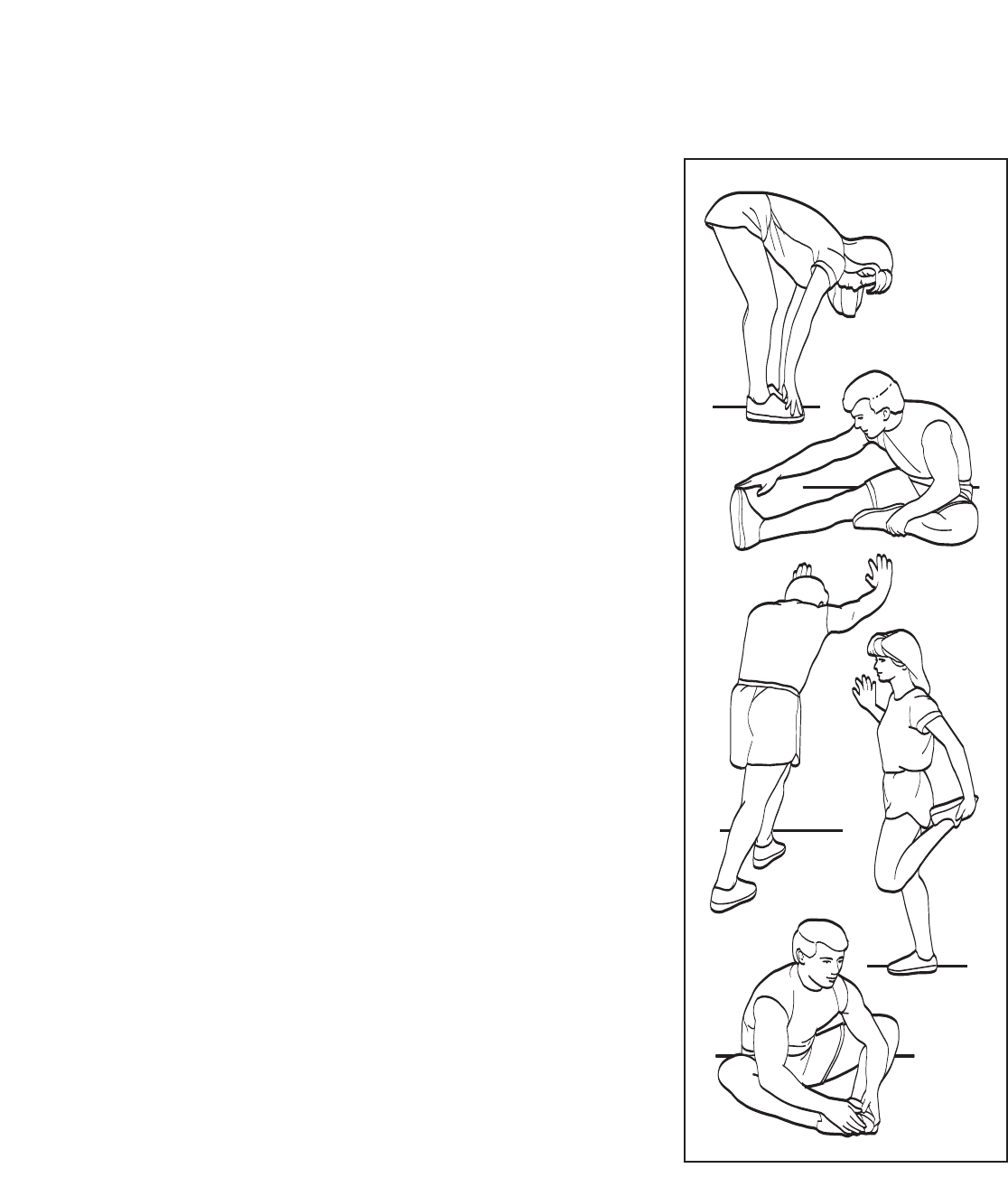
SUGGESTED STRETCHES
The correct form for several basic stretches is shown at the right. Move slowly as you stretch—never bounce.
1.Toe Touch Stretch
Stand with your knees bent slightly and slowly bend forward from
your hips. Allow your back and shoulders to relax as you reach
down toward your toes as far as possible. Hold for 15 counts, then
relax. Repeat 3 times. Stretches: Hamstrings, back of knees and
back.
2. Hamstring Stretch
Sit with one leg extended. Bring the sole of the opposite foot toward
you and rest it against the inner thigh of your extended leg. Reach
toward your toes as far as possible. Hold for 15 counts, then relax.
Repeat 3 times for each leg. Stretches: Hamstrings, lower back and
groin.
3. Calf/Achilles Stretch
With one leg in front of the other, reach forward and place your
hands against a wall. Keep your back leg straight and your back foot
flat on the floor. Bend your front leg, lean forward and move your
hips toward the wall. Hold for 15 counts, then relax. Repeat 3 times
for each leg. To cause further stretching of the achilles tendons,
bend your back leg as well. Stretches: Calves, achilles tendons and
ankles.
4. Quadriceps Stretch
With one hand against a wall for balance, reach back and grasp one
foot with your other hand. Bring your heel as close to your buttocks
as possible. Hold for 15 counts, then relax. Repeat 3 times for each
leg. Stretches: Quadriceps and hip muscles.
5. Inner Thigh Stretch
Sit with the soles of your feet together and your knees outward. Pull
your feet toward your groin area as far as possible. Hold for 15
counts, then relax. Repeat 3 times. Stretches: Quadriceps and hip
muscles.
1
2
3
4
5

30
PART LIST—Model No. GGTL59606.0 R0307A
Key No. Qty. Description Key No. Qty. Description
1 2 Step Tech Decal
26 3/4" Screw
3 43 Screw
4 1 Catch
5 10 Foot Rail Screw
6 2 Isolator
7 8 Hood Screw/Isolator Screw
8 4 Star Washer
9 2 Platform Bolt, Back
10 2 Platform Bolt, Front
11 4 Belt Guide Screw
12 2 Belt Guide
13 1 Left Handrail
14 1 Right Handrail
15 2 Frame Pivot Bolt
16 1 Left Foot Rail
17 1 Right Foot Rail
18 1 Motor Pivot Pin
19 1 Motor Bracket
20 1 Console Frame Support
21 1 Latch Pin Assembly
22 2 Motor Washer
23 8 3/8" Star Washer
24 2 Motor Bolt
25 2 Motor Tension Bolt
26 1 Motor Belt
27 1 Drive Motor
28 2 Frame Washer
29 4 U-nut
30 2 Motor Nut
31 2 Lift Frame Bolt
32 2 Lock Nut
33 10 1/2" Screw
34 1 Console
35 2Fan Screw
36 1 Power Cord
37 1 Console Fan
38 1Controller
39 1Reset/Off Circuit Breaker
40 1 Filter Wire
41 1Hood
42 1 Front Roller Bushing
43 1 Lift Frame
44 2 Upright Endcap
45 1Front Roller Bolt
46 1 Magnet
47 1 Front Roller/Pulley
48 1Walking Belt
49 1 Walking Platform
50 6 Rear Roller Washer/Isolator Washer
51 1 Rear Roller
52 1 Left Rear Endcap
53 2 Rear Roller Bolt
54 1 Right Rear Endcap
55 1 Hex Key
56 2 Lift Frame Nut
57 1 Front Roller Ground Wire
58 1 Frame
59 1 Belly Pan
60 1 Reed Switch Clip
61 1 Console Ground Wire
62 1 Power Cord Grommet
63 1 Reed Switch
64 4 Console Bolt
65 4 Extension Leg Bolt
66 1 Console Wire
67 4 Extension Leg Nut
68 2 Caution Decal
69 1 Warning Decal
70 4 Platform Nut
71 7 Cable Tie
72 1 Incline Motor Pin, Lower
73 1 Latch Housing
74 1 Console Lens
75 1 Incline Motor Wire
76 1 Access Door
77 1 Wire Harness
78 2 Extension Leg Endcap
79 1 Key/Clip
80 2 Front Wheel
81 2 Wheel Pin
82 4 Base Pad
83 6 1" Tek Screw
84 1 Left Upright
85 1Console Base
86 1 Incline Motor Pin, Upper
87 3 Hair Pin Cotter Pin
88 1Incline Motor
89 2Extension Leg
90 2 Rear Roller Bracket
91 2Lock Washer
92 3 Hood Clip
93 4 Wire Tie
94 2 Endcap Pad
95 2Roller Bracket Screw
96 1 Lift Frame Ground Wire
97 1 Left Upper Body Arm w/Grip
98 1Right Upper Body Arm w/Grip
99 2 Hand Grip
100 2 Insert Screw
To locate the parts listed below, see the EXPLODED DRAWING starting on page 32.

31
Key No. Qty. Description Key No. Qty. Description
101 2 Resistance Assembly
102 4 Flat Washer
103 4 4 1/2" Bolt
104 2 Upper Body Arm Insert
105 2 2 3/4" Upright Bolt
106 2 1" Upright Bolt
107 1 Right Upright
108 1 Base
# 1 14" Blue Wire, 2F
# 1 12" Blue Wire, 2F
# 1 16" Red Wire, M/F
# 1 14" Black Wire, M/F
# 1 8" Green Wire, F/R
# 1 20" Blue Wire, M/F
#1 User’s Manual
“#” indicates a non-illustrated part.
Specifications are subject to change without notice.
16
9
12
11
15
10
46
47
10
49
48
9
58
51
53
50
52
83 54
33
57
50
53
17
12
15
55
70
70
11
69
7
7
7
7
1
1
6
6
4
3
70
70
5
5
5
5
5
5
5
90
90
95
95
5
91
91
83
50
50
50
50
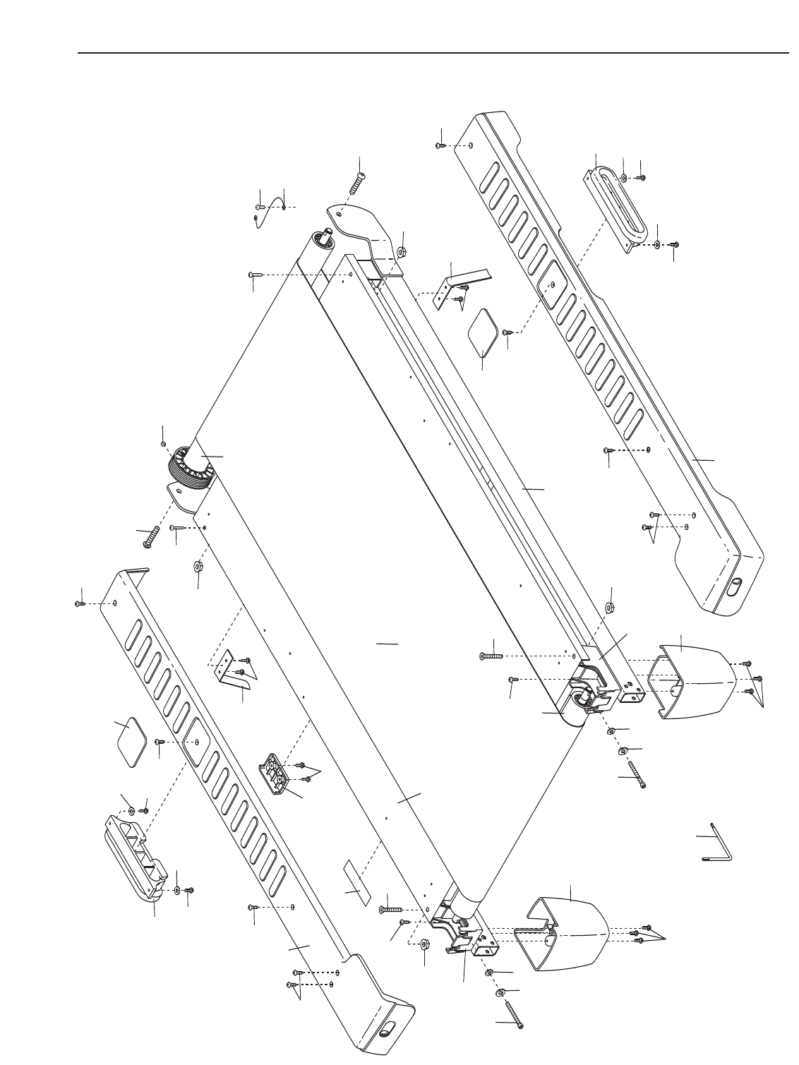
EXPLODED DRAWING A—Model No. GGTL59606.0 R0307A
32
2
59
2
2
2
2
41
33 38
40
28
43
28
32
32
18
87 22
25
25 22
27
30
23
26
19
24
30
42
7
7
7
45
63
60
33
36
62
39
96
92
92
92
33
33
33
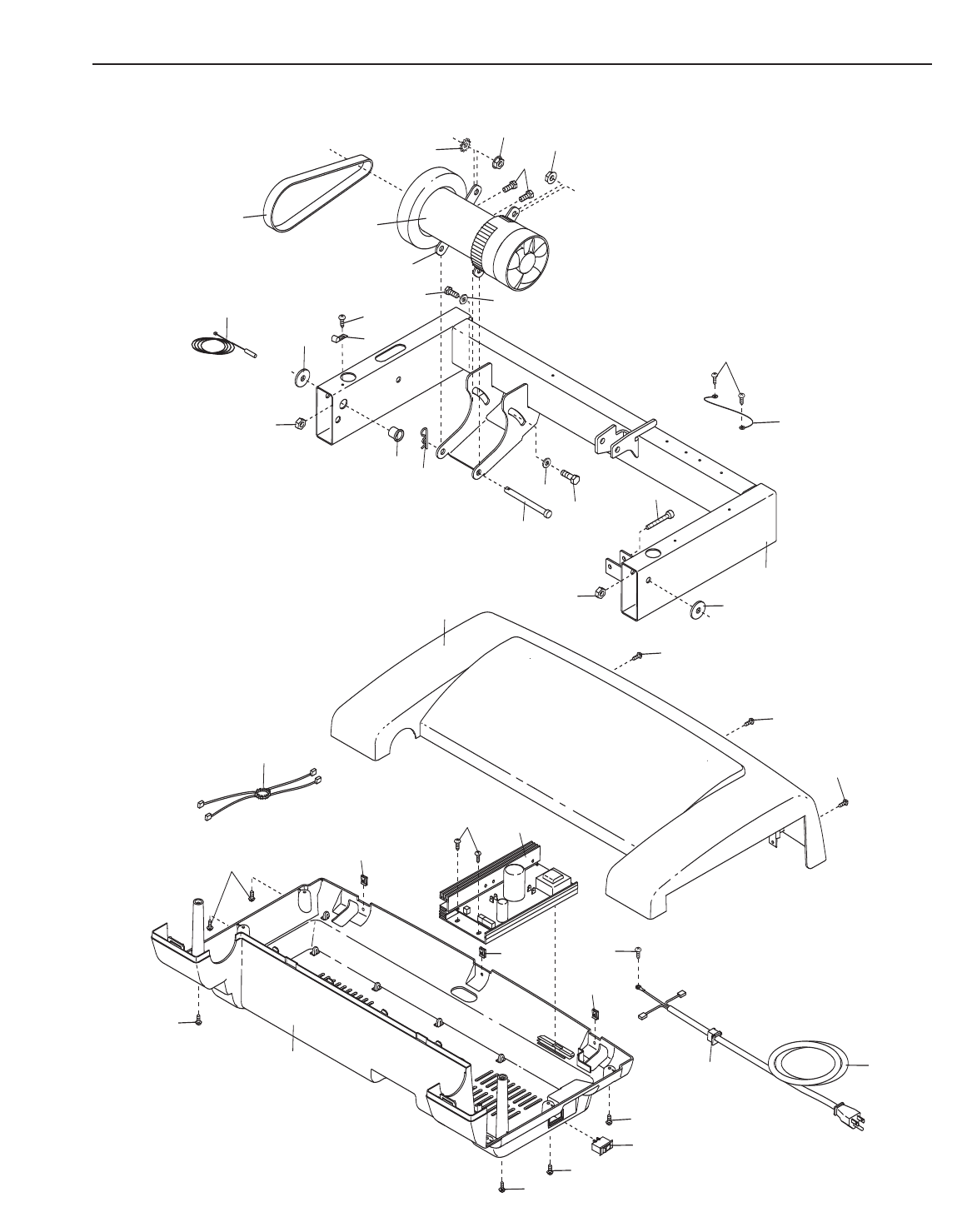
EXPLODED DRAWING B—Model No. GGTL59606.0 R0307A
84
73
77
82
83
33
82 83
68
68
72
87
86
88
80
82
83
29
29
67
65
65
31
56
3
44
3
44
31
56
8
8
64
64
8
64
8
21
64
20
94
83
89
81
78
82
83
80
67
89
81
78
94 83
77
3
87
103
102
23
97
98
23
101
99
99
104
102
103
100
23
105
106
23
23
105
23
100
101
104
106
107
108
75
34
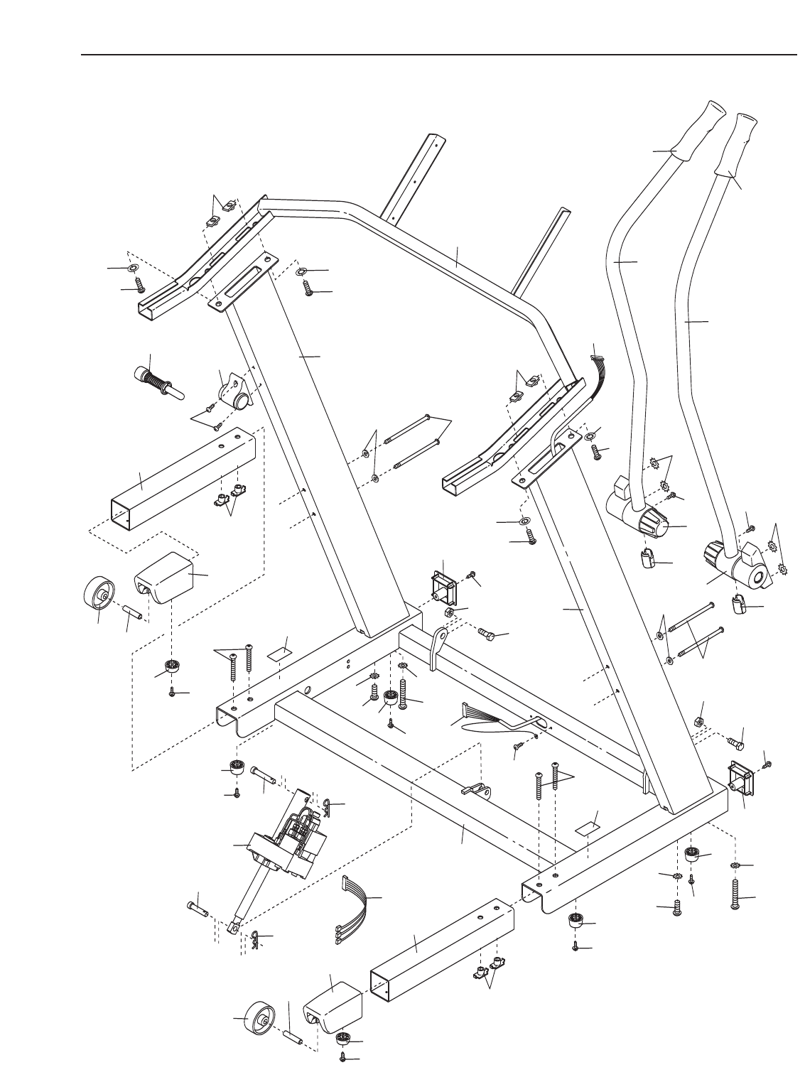
EXPLODED DRAWING C—Model No. GGTL59606.0 R0307A
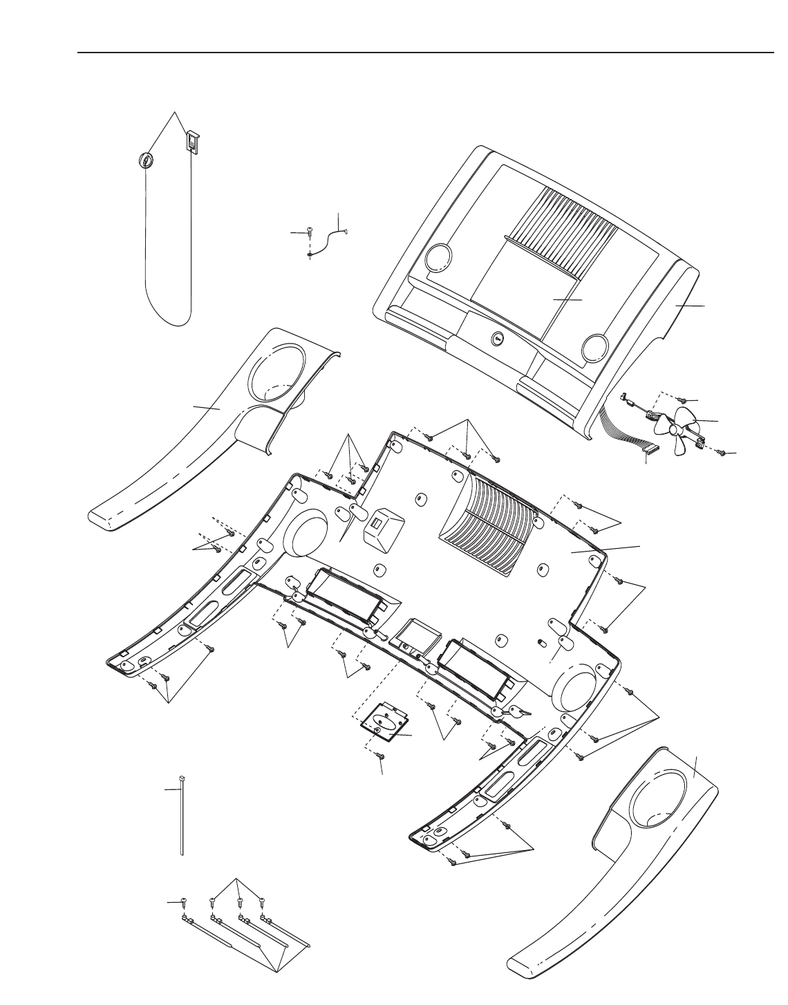
3
76
79
71
37
35
35
3
3
14
13
3
3
3
3
3
3
3
34
3
3
3
85
66
93
33
7
33
61
74
35
EXPLODED DRAWING D—Model No. GGTL59606.0 R0307A

Part No. 249013 R0307A Printed in USA © 2007 ICON IP, Inc.
ORDERING REPLACEMENT PARTS
Toorder replacement parts, please see the front cover of this manual. To help us assist you, be prepared to pro-
vide the following information when contacting us:
• the MODEL NUMBER of the product (GGTL59606.0)
• the NAME of the product (GOLD’S GYM CROSSTRAINER 600 treadmill)
• the SERIAL NUMBER of the product (see the front cover of this manual)
• the KEY NUMBER and DESCRIPTION of the part(s) (see the EXPLODED DRAWING and the PART LIST
starting on page 30)
LIMITED WARRANTY
ICON Health & Fitness, Inc. (ICON) warrants this product to be free from defects in workmanship and
material under normal use and service conditions. The drive motor is warranted for ten (10) years after
the date of purchase. Parts and labor are warranted for ninety (90) days after the date of purchase.
This warranty extends only to the original purchaser. ICON's obligation under this warranty is limited to
replacing or repairing, at ICON's option, the product through one of its authorized service centers. All re-
pairs for which warranty claims are made must be pre-authorized by ICON. If the product is shipped to a
service center, freight charges to and from the service center will be the customer’s responsibility. For in-
home service, the customer will be responsible for a minimal trip charge. This warranty does not extend
to any product or damage to a product caused by or attributable to freight damage, abuse, misuse, im-
proper or abnormal usage or repairs not provided by an ICON authorized service center; products used
for commercial or rental purposes; or products used as store display models. No other warranty beyond
that specifically set forth above is authorized by ICON.
ICON is not responsible or liable for indirect, special or consequential damages arising out of or in con-
nection with the use or performance of the product or damages with respect to any economic loss, loss
of property, loss of revenues or profits, loss of enjoyment or use, costs of removal or installation or other
consequential damages of whatsoever nature. Some states do not allow the exclusion or limitation of in-
cidental or consequential damages. Accordingly, the above limitation may not apply to you.
The warranty extended hereunder is in lieu of any and all other warranties and any implied warranties of
merchantability or fitness for a particular purpose is limited in its scope and duration to the terms set
forth herein. Some states do not allow limitations on how long an implied warranty lasts. Accordingly, the
above limitation may not apply to you.
This warranty gives you specific legal rights. You may also have other rights which vary from state to state.
ICON HEALTH & FITNESS, INC., 1500 S. 1000 W., LOGAN, UT 84321-9813
