Goldstar LW5200ER User Manual ROOM A/C Manuals And Guides 1006128L
User Manual: Goldstar LW5200ER LW5200ER GOLDSTAR ROOM A/C - Manuals and Guides View the owners manual for your GOLDSTAR ROOM A/C #LW5200ER. Home:Heating & Cooling Parts:Goldstar Parts:Goldstar ROOM A/C Manual
Open the PDF directly: View PDF ![]() .
.
Page Count: 13

website http://www,lgservice,com
e-mail http://www,lgeservice,com/techsup,html
AS _ ]gN]':RGY S'i'AR _ l_ar_er_
g_tt_Mln_ Nr t+_erKv ¢ffi_'ieN);
ROOMAIRCONDITIONER
UAL
Please read the operating instructions and safety precautions carefully
and t:horoughly before installing and operating your room air conditioner.
MANUEL
CL D'UTILISATION
T
Veuiliez lire a_entivement et en entier ce guide d'utilisation et les
mesures de securite ci4ncluses avant de proceder a I'installation et au
fonctionnement de votre climatiseun
DEAI_EDE
,_raci6ny las precauciones de
de instalar y operar su
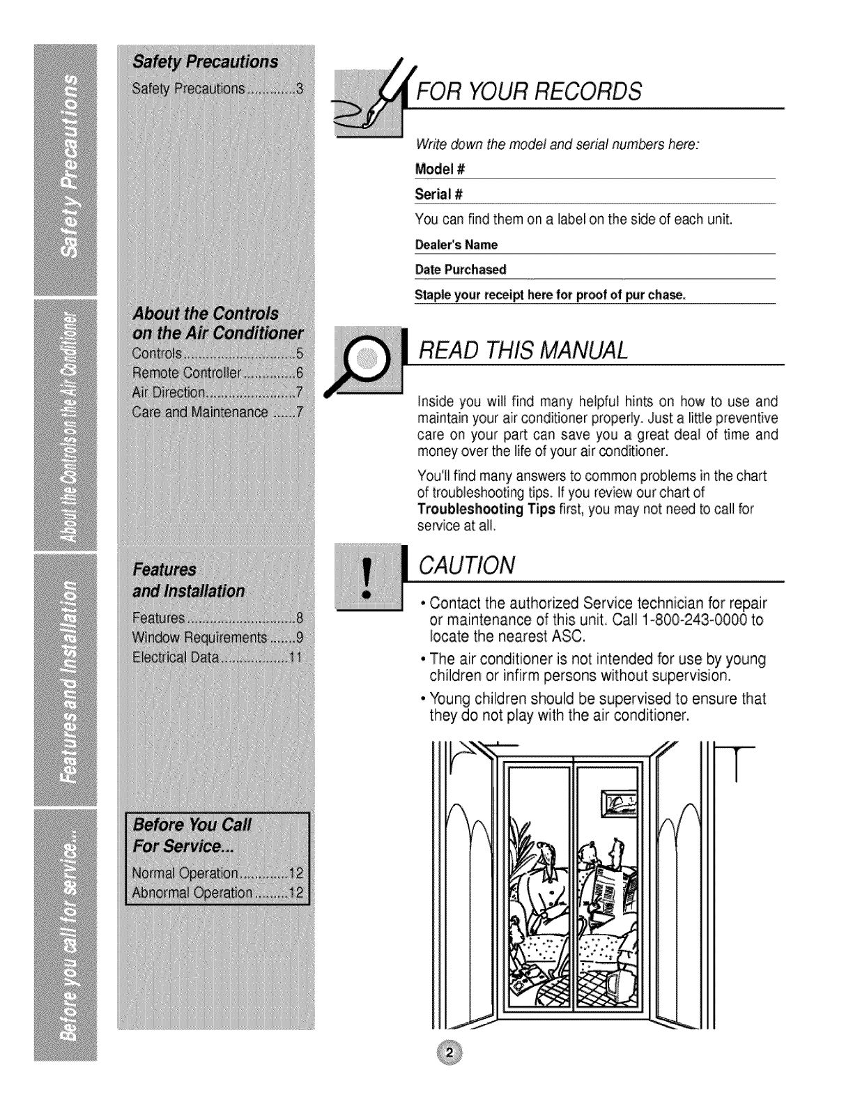
FOR YOUR RECORDS
Write down the model and serial numbers here:
Model #
Seria! #
You can find them on a label on the side of each unit.
_aler's Name
Date Purchased
Stapleyour receipt herefor proofof pJr cha_.
READ THIS MANUAL
inside you will find many helpful hints on how to use and
maintain your air conditioner properly. Just a little preventive
care on your part can save you a great deal of time and
money over the life of your air conditioner.
You'll find many answers to common problems in the chart
of troubleshooting tips If you review our cha_ of
Troubleshooting Tips first, you may not need to call for
service at all.
° Contact the authorized Service technician for repair
or maintenance of this unit. Call 1.-800-243-0000 to
locate the nearest ASC.
•The air conditioner is not intended for use by young
children or infirm persons without supervision.
• Young children should be supervised to ensure that
they do not play with the air conditioner.
T
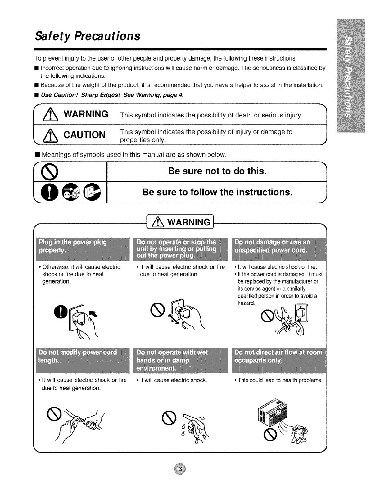
Safety Pre utions
To prevent injury to the user or other people and property damage, the following these instructions.
m _n_rrect operation due to ignoring instructions will cause harm or damage, The seriousness is classified by
the following indications,
[] Because of the weight of the product, it is recommended that you have a helper to assist in the installation.
[] Use Caution! Sharp Edges! See Warning, p_ge 4.
(-_ This symbol indicates the possibifity of death or serious injury _']
.. ,4"\ CAUTION This symbol indicates the possibility of injury or damage to
\ properties on!y _.)
IMeanings of symbols used in this manual are as shown below,
Ill Be sure not to do this. J
_ _.,_, Be sure to follow the instructions.
I w.,,RN,NG!
•Otherwise, it will cause electric
shock or fire due to heat
generation.
• It will cause electrc shock or fire
due to heat generation.
•It will cause electric shock or fire
due to heat generation.
•it wil_cause electric shock.
• it will _use electric shock or fire.
• Itthe powercord is damaged,it must
bereplacedby the manulactureror
itsserviceagentor a similarly
qualifiedpersonin orderto avoida
hazard.
•This _uld _eadto health problems.
®
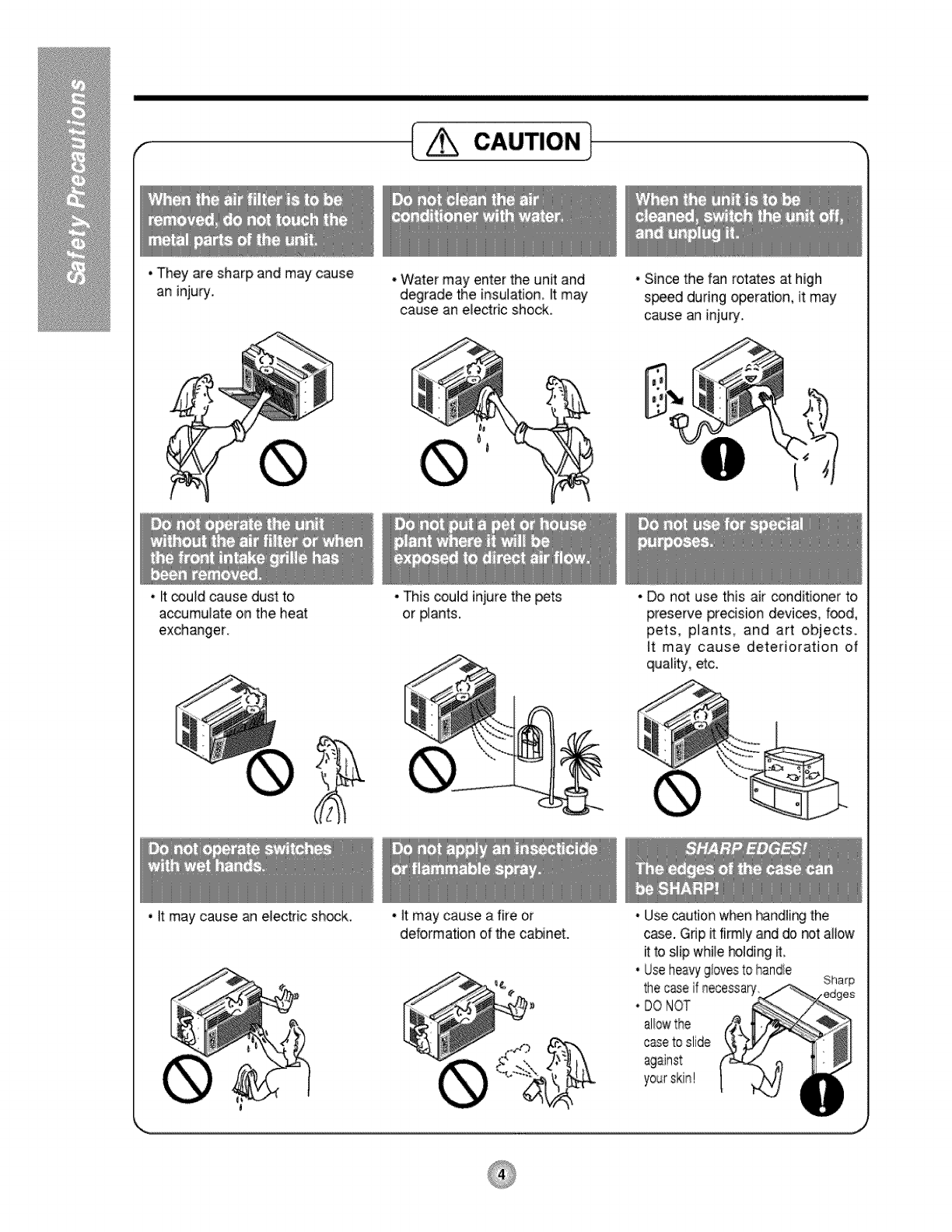
• They are sharp and may cause
an injury,
cio.l
* Water may enter the unit and
degrade the insulation, _tmay
cause an e_ectricshock,
•Since the f_ rotates at high
s_ed during o_ration, it may
cause an injury.
•_tcould cause dust to
accumulate on the heat
exchanger.
• This could injure the pets
or #ants.
•_tmay cause an electric shock, • it may cause a fire or
deformation of _e cabinet.
• Do not use this air conditioner to
preserve precision devices, food,
pets, pilants, and art objects,
it may cause deterioration of
quality, etc.
•Usecaution when _ndl[ng the
case. Gdpit firmly and do r#t allow
ffto slip while hoJdingit.
•Useheavyg/oresto handie Sharp
thecaseif necessary
•DONOT
allowthe
c_e to slide
against
About the ntro, ls on the air conditioner
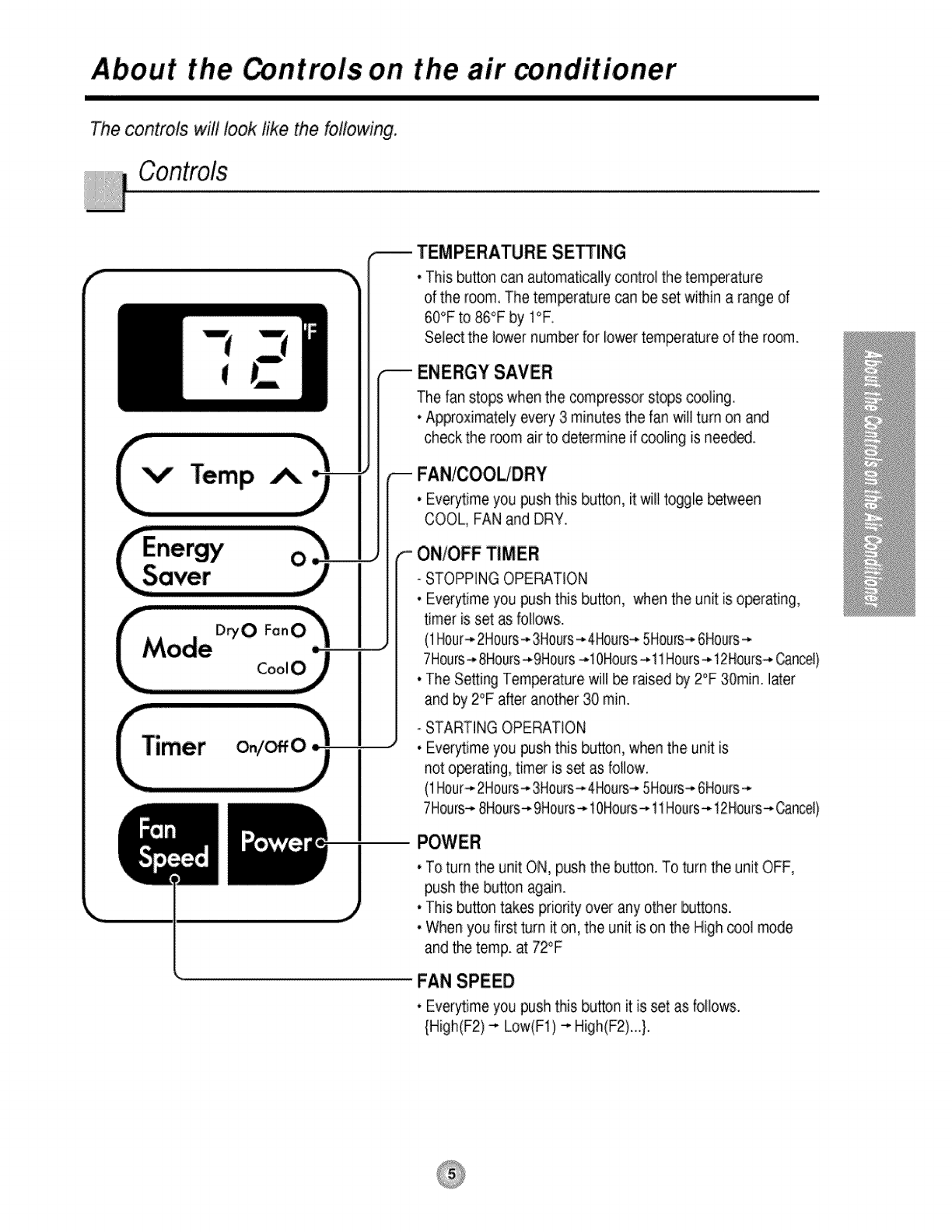
The controls will look like the following.
V" Temp
f,.-
TEMPERATURE SETTING
•This button can automatically control the temperature
of the room, The temperature _n be set wi_in a range of
60°F to 86°F by I°F
Select the lower number for lowertemperature of the room.
ENERGY SAVER
The fan stops when the compressor stops _oIing.
• Approximately every 3 minutes the fan will turn on and
check the r_m air to determine if cooling is need_.
FAN/OOOLtDRY
• Everytime you push this button, it wilt toggie between
COOL, FAN and DRY.
ON/OFF TIMER
- STOPPING OPERATION
• Every,time you push this button, when the unit is operating,
timer is set as followsi.
(1Hour-,-2Hours--,-3Hou_s--,.4Hours---5Hours--,.6Hours--*
7Hours_ 8Hours-,.9Hours-,.10Hours-,.11Hours-,-12Hours-,.Cancel)
• The Setting Temperature will _ rased by 2°F 30rain. later
and by 2°F after another 30 rain.
- STARTING OPERATION
• Everytime you push this button, when the unit is
not operating, timer is set as follow.
(1Hour_ 2Hours-*3Hours_4Hours-*5Hours-,6Hours-*
7Hours-*8Hours-*9Hours-*10Hours--*11Hours-*12Hours_Cancel)
• To turn the unit ON, push the button. To turn the unit OFF,
push the button again.
• This button takes priodty over any other buttons.
• When you first turn it on, the unit is on the High cool mode
and the temp. at 72°F
FAN SPEED
•Everytime you push this button it is set as foliows.
{High(F2) _ Low(Ft) _ High(F2)...}.
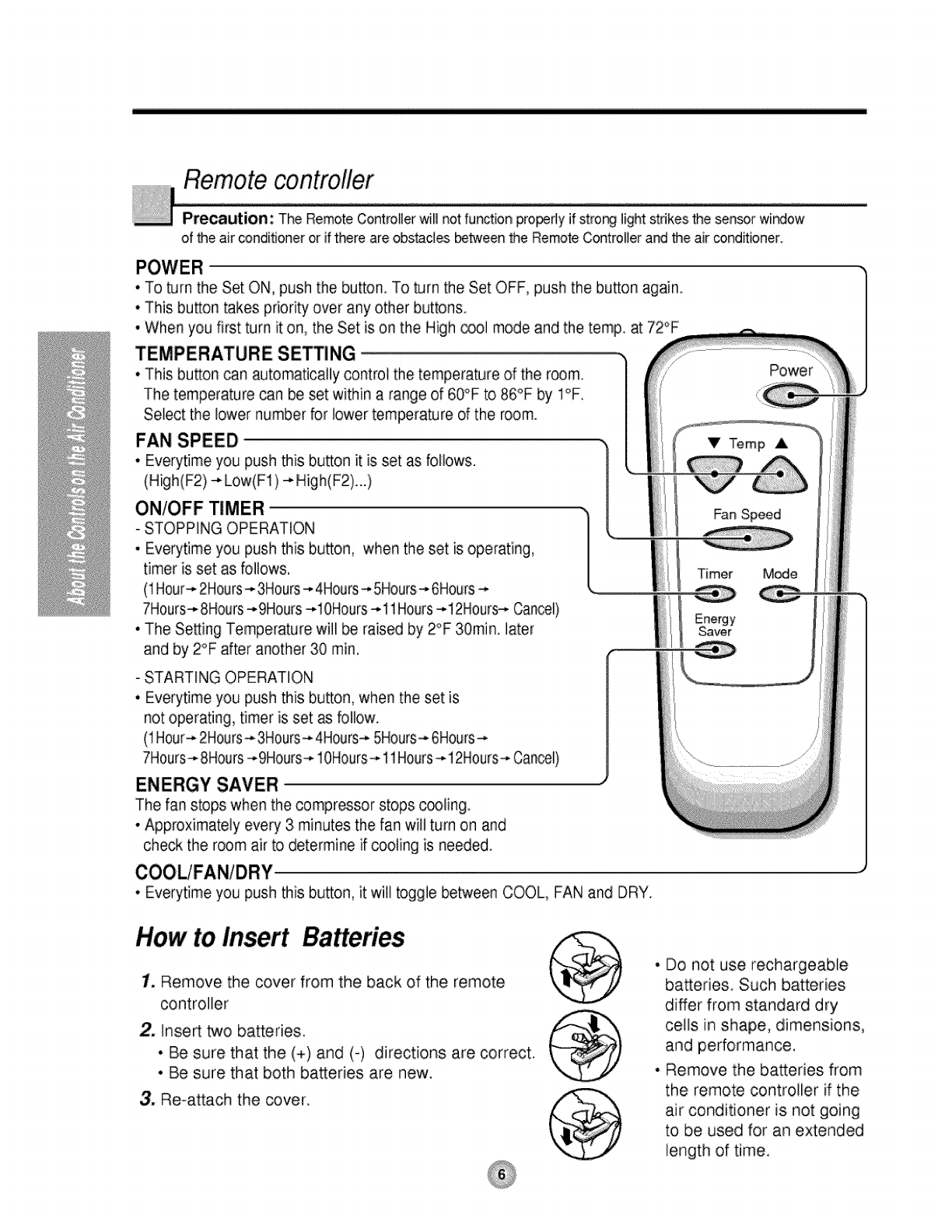
Remote controfler
Precaution: The RemoteControllerwirl not function properly Jfstror_g_ightstnkesthe sensorwir_ow
of the air conditioneror if there are obstacJesbetweenthe RemoteControllerand the air condRioner.
• To turn the Set ON, push the button. To turn the Set OFF, push the button again
• This button takes priority over any other buttons.
• When you first turn it on, the Set is on the High _ol mode and the temp. at 72°F
TEMPERATURE SETTING
•This button can automatically control the temperature of the room
The temperature can be set within a range of 60°F to 86°F by I°R
Select the lower number for lower temperature of the room.
FAN SPEED
•Everytime you push this button it is set as follows.
(High (IF2)---Low(F1 ) -_Hig h(F2)...)
ON/OFF TIMER ,[
-STOPPING OPERATION
• Everytime you push this bu_on, when the set is operating,
timer is set as follows.
(1Hour-*2Hours-* 3Hours-* 4Hours-*5Hours-* 6Hours-*
7Hours-* 8Hours-*9Hours -*lOHours -*11Hours -*12Hours-,-Cancel)
• The Setting Temperature will be raised by 2°F 30rain. later
and by 2°F alter another 30 min,
- STARTING OPERATION
• Everytime you push this button, when the set is
not operating, timer is set as follow.
(1Hour-*2Hours_. 3H0urs-,.4Hours-,-5Hours--,.6Hours-_
7Hours-* 8Hours---9Hours-,,10Hours--*11Hours-* !2Hours-* Cancel)
ENERGY SAVER
The fan stops when the compressor stops c_ling
• Approximately every 3 minutes the fan will turn on and
check the room air to determine if cooling is needed
Power
VTemp A
Fan Speed
Timer M_e
• Everytime you push this button, it will toggle between COOL, FAN and DRY.
How to Insert
1. Remove the cover from the back of the remote
controller
2. Inse_ two batteries.
• Be sure that the (+) and (-) directions are correct.
• Be sure that both batteries are new.
3. Re-attach the cover.
•Do not use rechargeable
batteries Such batteries
differ from standard dry
ceils in shape, dimensions,
and performance.
• Remove the batteries from
the remote controller if the
air conditioner is not going
to be used for an extended
length of time.
Additional controls and important information.
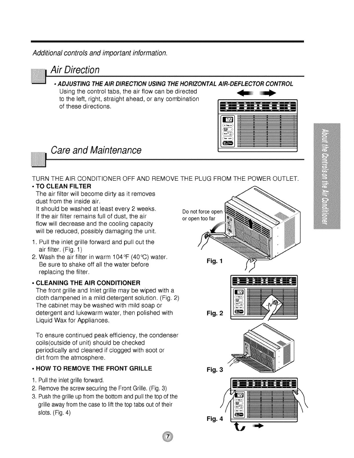
Air Direction
•ADJUSTING THE AIR DIRECTION USING THE HORIZONTAL AIR.DEFLECTOR CONTROL
Using the control tabs, the air flow can be directed
to the le_, right, straight ahead, or any combination
of these directions.
Care and Maintenance
TURN THE AIR CONDITIONER OFF AND REMOVE THE PLUG FROM THE POWER OUTLET.
. TO CLEAN FILTER
The air filter will become dirty as it removes
dust from the inside air.
It should be washed at least every 2 weeks. Do not forceopen
If the air filter remains full of dust, the air or opent_ far
flow will decrease and the cooling capacity
will be redu_d, possibly damaging the unit.
1. Pull the inlet grille forward and pull out the
air filter. (Fig. 1)
2. Wash the air filter in warm 104_ (40_) water.
Be sure to shake off all the water before
replacing the filter.
•CLEANING THE AIR CONDITIONER
The front grille and Inlet grille may be wiped with a
cloth dampened in a mild detergent solution. (Fig. 2)
The cabinet may be washed with mild soap or
detergent and lukewarm water, then polished with
Liquid Wax for Appliances.
Fig. 1
Fig, 2
To ensure continued peak efficiency, the condenser
coils(outside of: unit) should be checked
periodically and cleaned if clogged with soot or
dirt from the atmosphere.
• HOW TO REMOVE THE FRONT GRILLE
1, Pull the inlet grille forward,
2, Remove the screw securing the Front Grille. (Fig. 3)
3. Push the grille up from the _ttom and pull the top of the
gdlle away from the case to lift the top tabs out of their
slots. (Fig. 4)
Fig, 3
Fig. 4
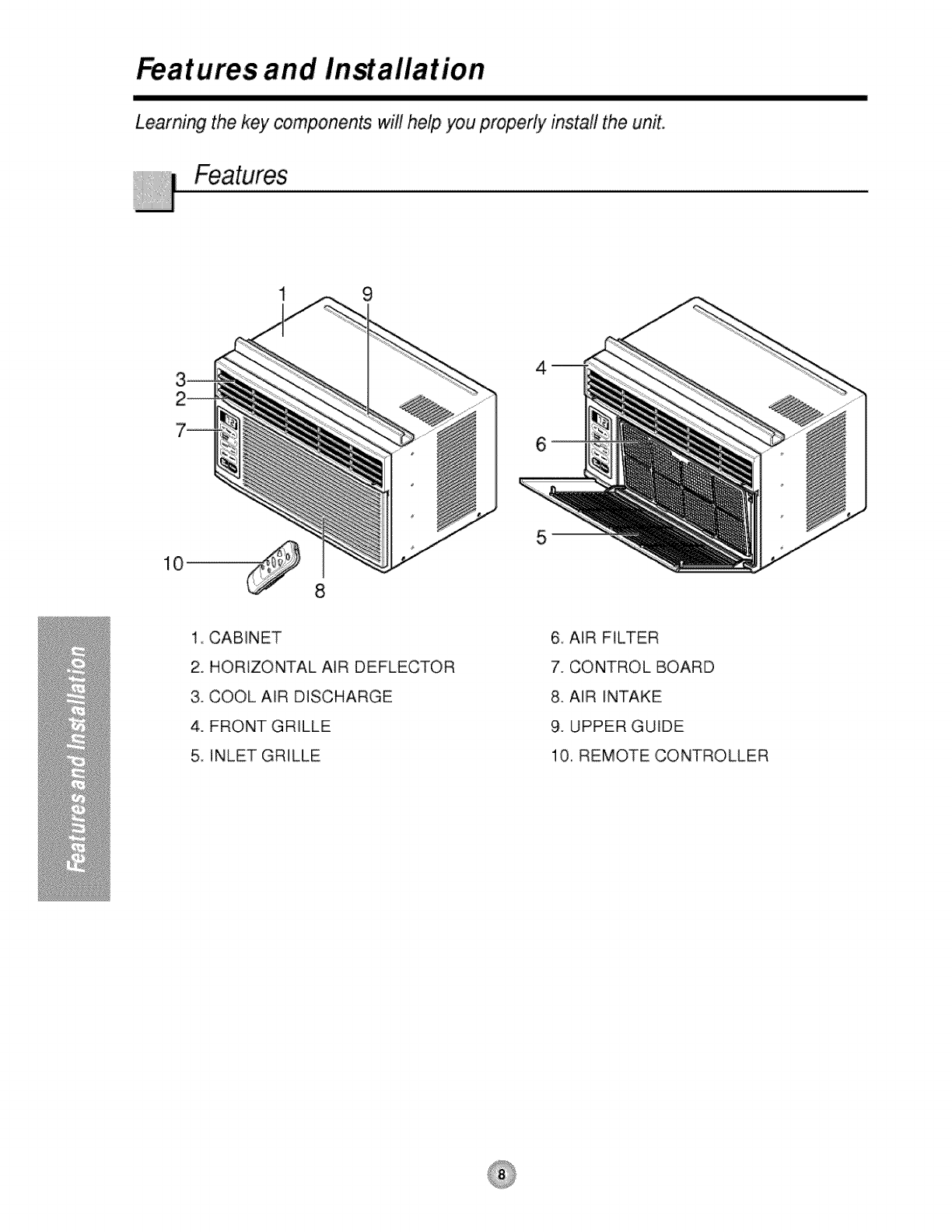
Features and InMallation
Learning the key components will help you properly install the unit.
1 9
1, CABINET
2. HORIZONTAL AiR DEFLECTOR
3. COOL AiR DISCHARGE
4. FRONT GRILLE
5, INLET GRILLE
6 AIR FILTER
7. CONTROL BOARD
8. AiR iNTAKE
9. UPPER GUIDE
10, REMOTE CONTROLLER
WindowRequirements
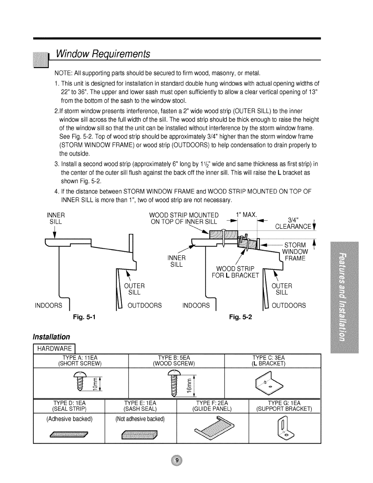
NOTE: All supporting parts should be secured to firm wood, masonry, or metal.
1. This unit is designed for installation in standard double hung windows with actual opening widths of
22" to 36" The upper and lower sash must open sufficiently to allow a clear vertical opening of 13"
from the bottom of the sash to the window st_l.
2Jf storm window presents interference, fasten a 2" wide wood strip (OUTER SILL) to the inner
window sill across the full width of the sill. The w_d strip should be thick enough to raise the height
of the window sill so that the unit can be installed without interference by the storm window frame.
See Rg. 5-2. Top dwood strip should be approximately 3/4" higher than the storm window frame
(STORM WINDOW FRAME) or wood strip (OUTDOORS) to help condensation to drain properly to
the outside.
3. install a se_nd wood strip (_proximate[y 6" long by 11iz"wide and same thickness as first strip} in
the center of the outer sill flush against the back off the inner sill. This will raise the L bra_et as
shown Fig, 5-2,
4. If the distance between STORM WINDOW FRAME and WOOD STRIP MOUNTED ON TOP OF
INNER SiLL is more than 1", two of wood strip are not necessa_,
INNER WOOD STRIP MOUNTED 1" MAX.
Fig. 5-1 Fig. 5-2
HARDWARE [
TYPE A: 11EA TYPE B: 5EA TYPE C: 3EA
(SHORTSCREW) _ (WOODSCREW) _ (L BRACKET)
. E
_ E
TYPE D: lEA
(SEALSTRIP)
(Adhesive backed)
TYPE E: lEA
(SASH SEAL}
(Notadhesivebacked)
TYPE F: 2EA
(GUIDE PANEL} TYPE G: lEA
(SUPPORT BRACKET)
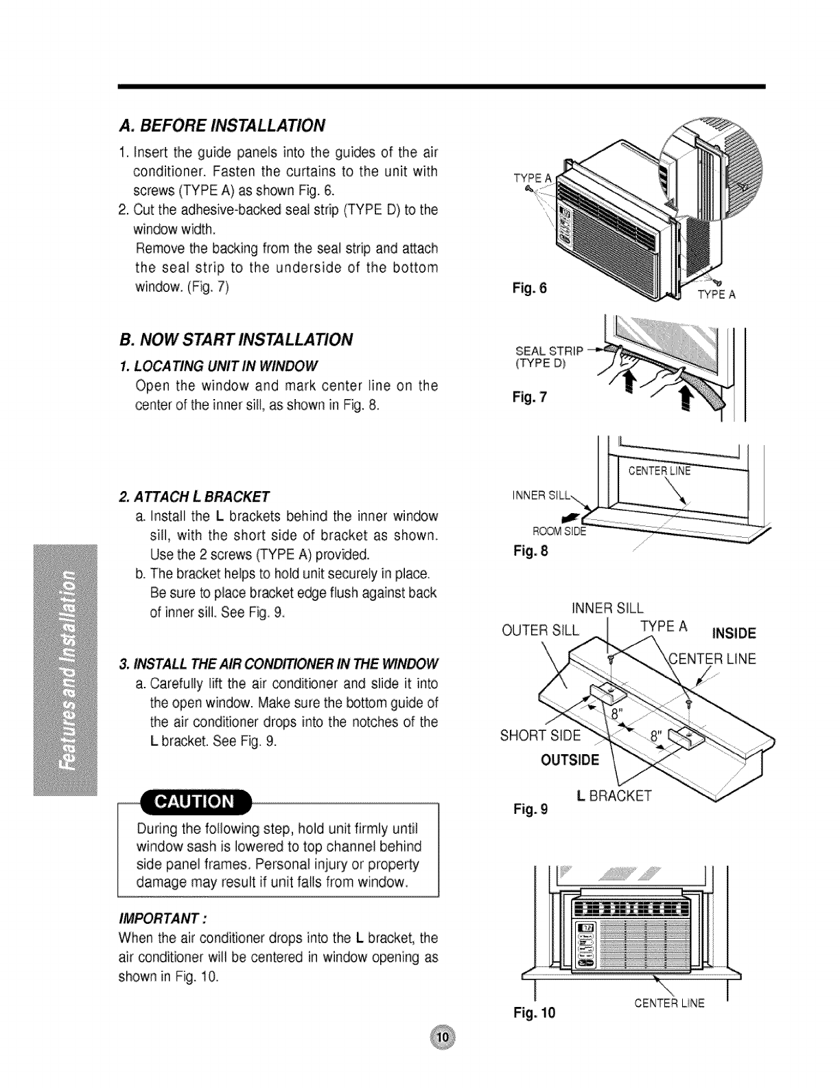
A. BEFORE INSTALLATION
1. Insert the guide panels into the guides of the air
conditioner. Fasten the curtains to the unit with
screws (TYPE A) as shown Fig. 6.
2. Cut the adhesive-back_ seal strip (TYPE D) to the
window width,
Remove the bacJ<.ingfrom the seal strip and a_ach
the seal strip to the underside of the bottom
window. (Fig. 7)
B. NOW START INSTALLATION
1. LOCA TING UNIT IN WINDOW
Open the window and mark center line on the
center of the inner sill, as shown in Fig. 8.
TYPEA
2. ATTACH LBRACKET
a. install the Lbrackets behind the inner window
sill, with the short side of bracket as shown.
Use the 2 screws (TYPE A) provided.
b. The bracket helps to hold unit securely in place.
Be sure to place bracket edge flush against back
of inner sill See Fig. 9.
&INSTALL THE AIR IN THE WINDOW
a. Carefully lift the air conditioner and slide it into
the open window. Make sure the bottom guide of
the air conditioner drops into the notches of the
L bracket. See Fig. 9.
Fig. 8
INNER SILL
OUTER SILL TYPE A INSIDE
\'\ LINE
SHORT SIDE
During the following step, hold unit firmly until
window sash is lowered to top channel behind
side panel frames. Personal iniury or prope_y
damage may result if unit falls from window.
IMPORTANT:
When the air conditioner drops into the Lbracket, the
air conditioner will be centered in window opening as
shown in Fig. 10.
Fig. 9
LBRACKET
i
Fig. i0
I
CENTERLiNE
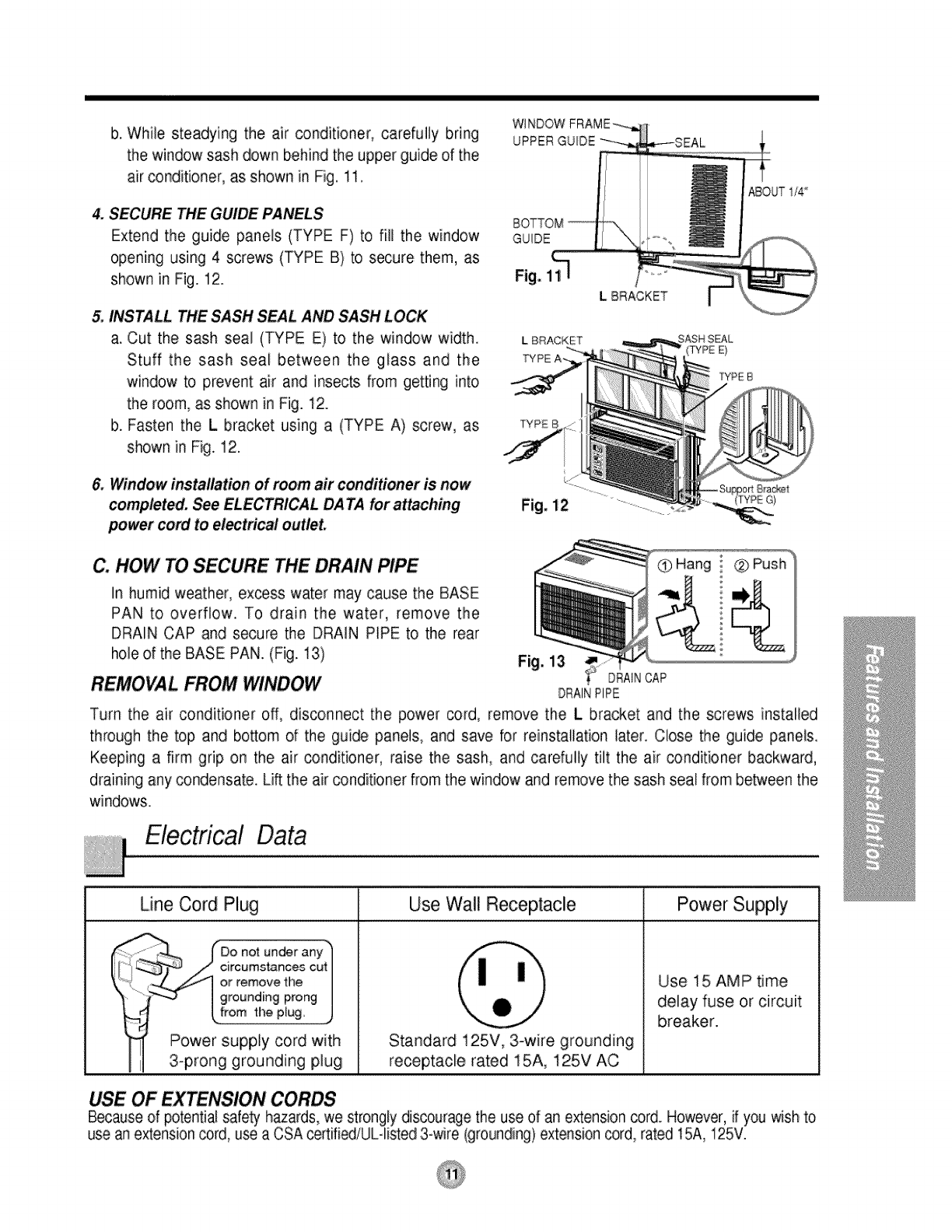
b. While steadying the air conditioner, carefully bring
the window sash down behind the upper guide of the
air conditioner, as shown in Fig, 11.
4. SECURE THE GUIDE PANELS
Extend the guide panels (TYPE F) to fill the window
opening using 4 screws (TYPE B) to secure them, as
shown in Fig. 12.
5. INSTALL THE SASH SEAL AND SASH LOCK
a. Cut the sash seal (TYPE E) to the window width
Stuff the sash seal between the glass and the
window to prevent air and insects from getting into
the room, as shown in Fig. 12.
b. Fasten the L bracket using a (TYPE A) screw, as
shown in Fig. 12.
&Window installation of room air conditioner is now
completed. See ELECTRICAL DATA for attaching
_wer cord to electrical outlet.
WlNDOWFRAME_-_
_-SEAL
]
L BRACKET I
ABOUT I/4
L BRACKET EAL
.... (TYPE E}
TYPE B
C. HOW TO SECURE THE DRAIN PIPE Hang l ®
In humid weather, excess water may cause the BASE
PAN to overflow. To drain the water, remove the
DRAIN CAP and secure the DRAIN PIPE to the rear
hole of the BASE PAN. (Fig. 13)
REMOVAL FROM WINDOW Fig. 13 DRAINCAP
DRAINPIPE
Turn the air conditioner off, disconnect the power cord, remove the L bracket and the screws installed
through the top and bottom of the guide panels, and save for reinstallation later. Close the guide panels.
Keeping a firm grip on the air conditioner, raise the sash, and carefully tilt the air conditioner backward,
draining any condensate. Lift the air conditioner from the window and remove the sash seal from be_een the
wi ndows.
Line Cord Plug
" _,_ (-Do not under any"
clrcumstance,_ cut
_.._/"--_ or remove the
I grounding prong
u
Power supply cord with
3-prong grounding plug
Use Wall Receptacle Power Supply
Standard 125V, 3-wire grounding
receptacle rated 15A, 125V AC
Use 15 AMP time
delay fuse or circuit
breaker.
USE OF EX N CORDS
Because of potential safety hazards, we strongly discourage the use of an extension cord. However, if you wish to
use an extension cord, use a CSA certified/UL-listed 3-wire (grounding) extension cord, rated 15A, 125V.
fore you for servia...
Troubleshooting TiPs save time and money!
Review the chart below first and you may not need to call for service.
Normal Operation
• You may hear a pinging noise caused by water being picked up and thrown against the condenser
on rainy days or when the humidity is high. This design feature helps remove moisture and improve
efficiency.
• Water will collect in the base pan during high humidity or on rainy days. The water may overflow
and drip from the outdoor side of the unit.
• The fan may run even when the compressor does not.
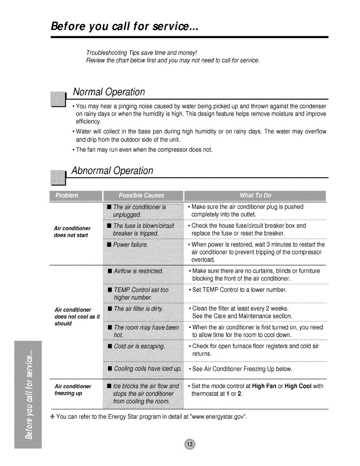
Abnormal Operation
Air conditioner
does not start
Air conditioner
does not cool as it
should
Air conditioner
freezing up
• Make sure the air conditioner plug is pushed
_mpletely into the outlet.
• Check the house fuse/circuit breaker box and
replace the fuse or reset the breaker.
° When power is restored, wait 3 minutes to restart the
air _nditioner to prevent tripping of the _mpressor
overload.
.Make sure there are no curtains, blinds or furniture
blocking the front of the air conditioner.
° Set TEMP Control to a lower number.
•Clean the filter at least every 2 weeks,
See the Care and Maintenance section.
° When the air conditioner is first turn_ on, you need
to allow time for the room to cool down.
• Check for open furnace floor registers and cold air
returns.
• See Air Conditioner Freezing Up below.
°Set the mode control at High Fan or High Cool with
thermostat at I or 2.
;P You can refer to the Energy Star pr_ram in detail at "www.energystar.gov".