Golf Tech PTUS001 Powertee User Manual Rental Agreement Cover
Golf-Tech Inc Powertee Rental Agreement Cover
manual

Tel: +44 (0) 1793 822566 Fax: +44 (0) 1793 822466
Enquiries@powertee.co.uk Web: www.powertee.co.uk
Unit 5 Woodside, South Marston Park, Swindon, Wiltshire SN3 4WA
Maintenance Manual
® PGA is a registered trademark of the Professional Golfers’ Association
1 Introduction
1.1 Components of the Mark II Power Tee
1.2 Health & safety
1.3 Warranty
1.4 Benefits to business
1.5 Golfer benefits
2 Power Tee Diagrams
2.1 Block diagram
2.2 Ball engine
2.3 Control panel
2.4 Sensors & terminology
2.5 Power switch
3 Routine Maintenance
3.1 Water issues
3.2 Daily maintenance
3.3 Monthly maintenance
3.4 Quarterly maintenance
4 Possible Bay Faults
4.1 Power Tee dead no display
4.2 Ball is not automatically replaced after each shot
4.3 Power Tee does not start when balls poured into hopper
4.4 Balls do not feed from hopper to tee
4.5 Broken Springs
4.6 Machine is noisy as tee lowers
5 Maintenance Procedures
5.1 Tee change
5.2 Reset Power Tee
5.3 Driving mat removal and refitting
5.4 Control panel change
5.5 Relacing hopper lid
5.6 Ball engine change
5.7 Ball engine cable (6 way connector)
6 DC Power Supply
7 Software Diagnostics
8 Switching Power Tee on Restarting/Resetting
Pg
2
3
3
3
3
4
4
5
5
5
6
7
7
7
7
8
8
9
9
10
10
10
11-12
13
14
14
15
15
16
17
Please Note: Should you require any further information regarding
Power Tee maintenance, please call us on +44 (0)1793 822566.
Introduction
As a Power Tee operator you are now in the top 5% of driving range vendors in the world,
giving your customers the very best service available. This comes at a price; instead of a
rubber backed mat with a tee protruding through it, each of your Power Tee bays now have
an automated teeing system which contains a machine with moving parts, sensors and
buttons. To make the best of your system, it should be in good working order at all times.
Unchecked, poor reliability can lead to discredit of the system and your business and even
false claims of lost balls by customers trying to get a free basket.
This manual is designed to help you get the most from your system. It is not a
replacement for customer services. Golf-Tech is available via the phone during
normal office hours and will be pleased to help talk you through problems or
replacement procedures. If you are uncertain about what needs doing to fix a
machine or how to do it, give us a call, we will respond with advice and if this fails we will
repair the machine for you.
A training course is available at which the attendee will learn all of the ins and outs of their
system, be given a spares and tool kit and be certified as a qualified Power Tee technician.
If you can learn how to repair machines during your warranty period of one year there is no
reason why you can’t be self-sufficient when you come out of warranty with postal
replacement of parts.
Golf-Tech is looking forward to working with you on Power Tee to help you to build your
business.
1
Information to user
Changes or modifications to this equipment, not expressly approved by Power Tee, may
void the user’s authority to operate this equipment.
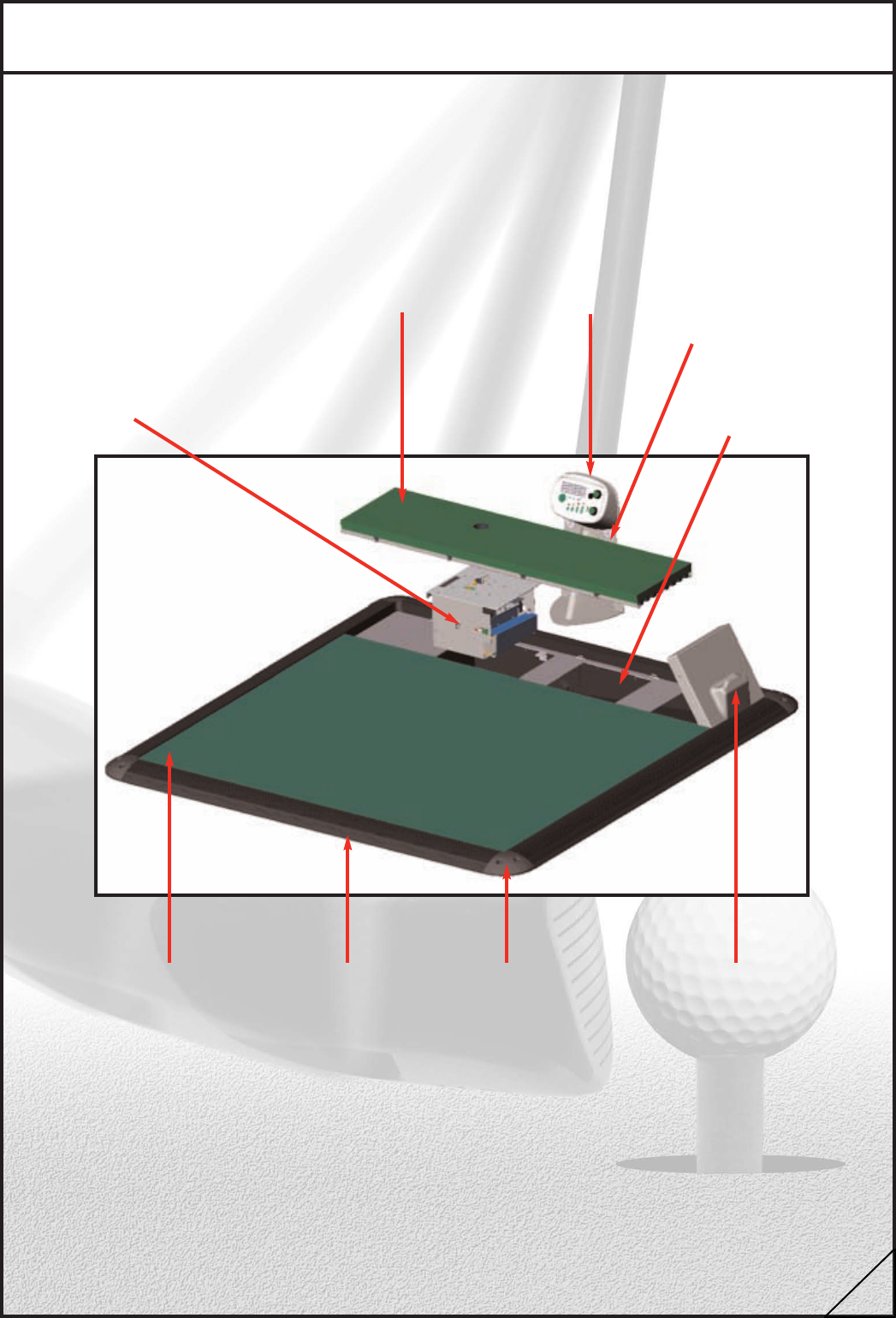
1.1 Components of the Mark II Power Tee
Control PanelFibre Driving Mat
Control Panel Stand
Ball Engine
Hopper Lid
Corner Moulding
Rubber Trim
Standing Mat
Hopper
2
1.2 Health & Safety
1.3 Warranty
1.4 Benefits to Business
1.5 Golfer Benefits
When working on a Power Tee bay, always handle the components with care, all
efforts are made to remove sharp edges from metal components, this will not stop you
cutting yourself if you handle the components carelessly. Pay particular attention to the
fixing lugs on the driving mat and beware of the metal cross braces when clearing out the
hopper.
Keep range customers out of the bay where you are working as they may step into the
hopper and trip, or unbalance the driving mat causing it to fall and cause injury.
Golf-Tech warrants that, for a period of one year after shipment, products
manufactured by it shall be free from defects in material and workmanship when
installed, serviced and operated within the specifications for which they were
designed. Golf-Tech will replace or repair any equipment or parts that fail provided that
nvestigation and factory inspection discloses that such defect developed under
normal and proper use by the original user. Golf-Tech’s liability under this warranty is
limited to such replacement or repair and it shall not be held liable in any form of action for
incidental or consequential damages to property or person. The foregoing is in lieu of all
other warranties, express or implied, including the warranties of merchantability and
fitness for particular purpose. Representations and warranties made by any person,
including dealers and representatives of seller, which are inconsistent or conflict with the
terms of this warranty (including but not limited to limitations of liability as set forth above),
shall not be binding upon Golf-Tech unless reduced to writing and approved by an expressly
authorised representative of Golf-Tech.
As well as being a highly desirable way to practice your golf on the driving range, Power Tee
offers significant benefits to the business operating the system. These come in the shape
of repeat purchases by golfers who have hit their balls quickly and have more time to spend
on the range, and repeat purchases by golfers who feel less tired by virtue of not having to
bend down to tee up each ball. In peak times when the range customers are queuing,
Power Tees will put through 30 to 40% more balls per hour than a conventional mat. Many
customers will go the extra mile to use a Power Tee over a normal mat. To get the best out
of your tees make sure you keep them in tip top shape and looking good.
Some golfers will see the Power Tee as a gimmick or lazy person’s toy. If you are on the
range and people are not using the Power Tees, find out why and offer them 5 free balls
showing them the tee heights and new ball button. Many top golfers talk about Swing
Grooving, Muscle Memory and Repetition. Power Tee also allows golfers to make small and
measured adjustments to each swing and see the net result on ball flight. The more you and
your team promote these benefits the more successful Power Tee will be for you.
3
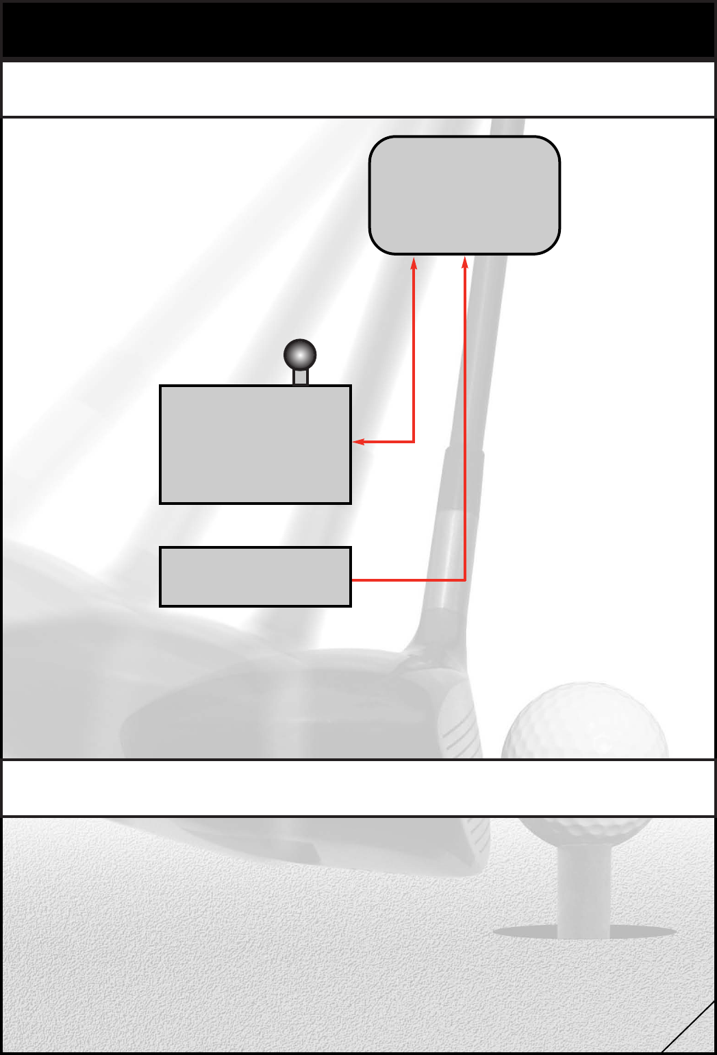
2 Power Tee Diagrams
2.1 Power Tee Diagrams
Control Panel with
display Radar &
Microphone
Ball Engine
28V Supply
Power Tee is the ultimate modular system comprising of two main components:
Control Panel & Ball Engine, both of which can be replaced on site and the
faulty component returned to us for repair and test in the factory.
In the event of failure, there are diagnostic features to the software that
will help you to identify which component has failed or jammed.
2.2 Ball Engine
The patented Ball Engine contains every moving part in the Power Tee. There are a few
operations you can carry out to repair the Ball Engine, namely spring
replacements and greasing of some moving parts, apart from these the Ball Engine will
generally be returned to base for bench repair.
The Ball Engine is connected to the Control Panel via a six-way cable.
4
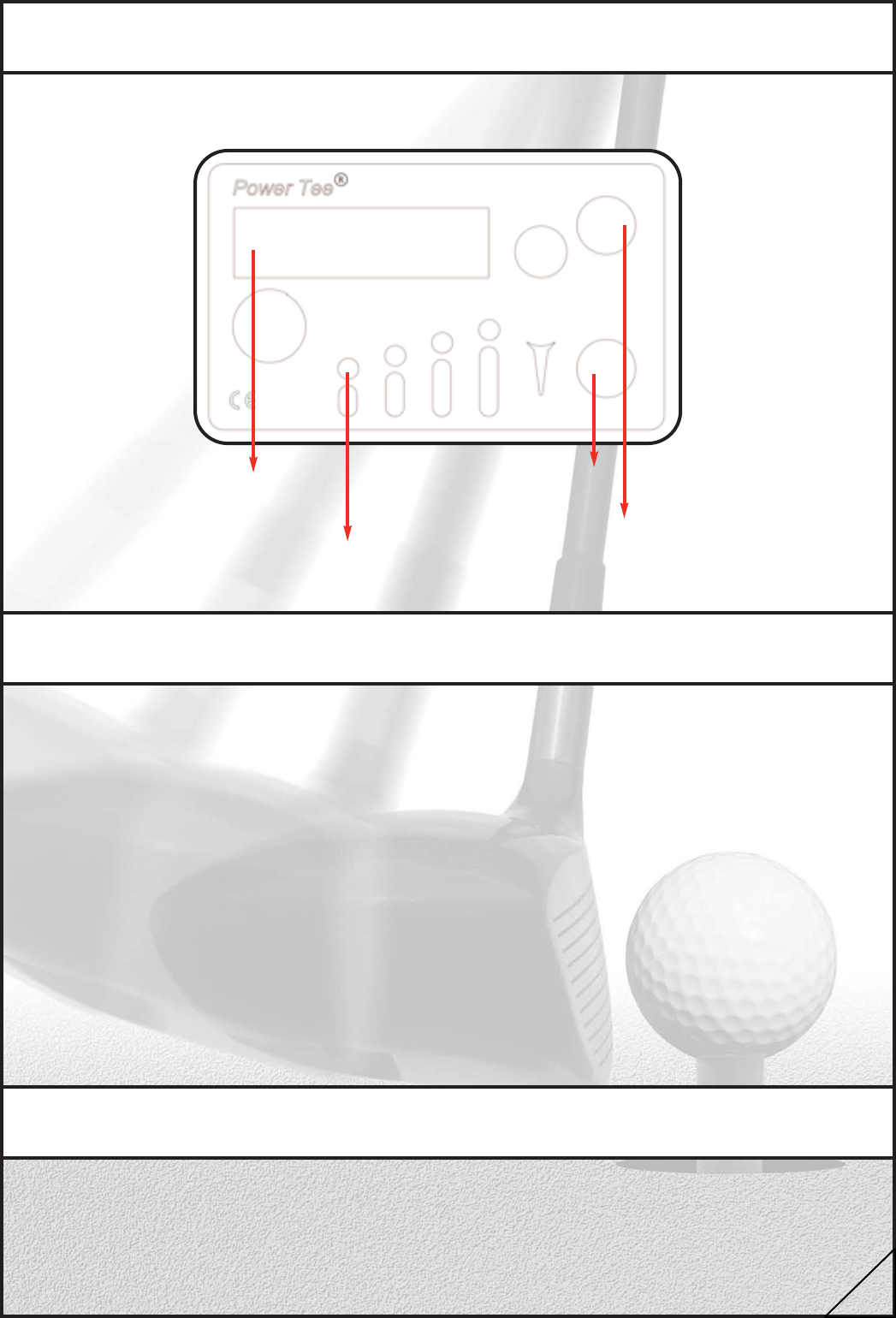
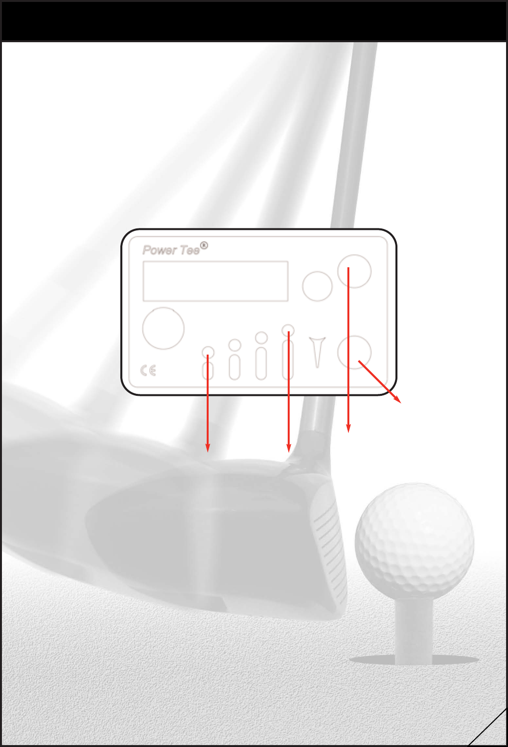
2.3 Control Panel
The Control Panel houses the display, the power switch, microphone, radar
module sensor and the two buttons for requesting a new ball or changing the tee height.
Ball counter &
diagnostic display
Four Tee
height indicators
Tee height button
New Ball Button
There are three main sensors you need to be aware of in a Power Tee.
These are:
1 Radar module sensor
2 Microphone
3 Ball in hopper sensor
The radar and microphone sensors combine to detect when a ball is struck. If a Power Tee
detects a swing combined with a specific type of loud sound (that of a ball being hit) the
Power Tee will present a new ball. If either of the sensors is not
working properly the machine will not present the ball automatically and the golfer will need
to press the “new ball button” on the Control Panel to have a new ball
presented.
The ball in hopper sensor is a light beam that travels along the scoop of the Ball
Engine. When balls are poured into the hopper, they roll onto the Ball Engine scoop where
the beam is broken and the machine starts its cycle presenting a new ball for the golfer to
start his practice.
2.4 Sensors & Terminology
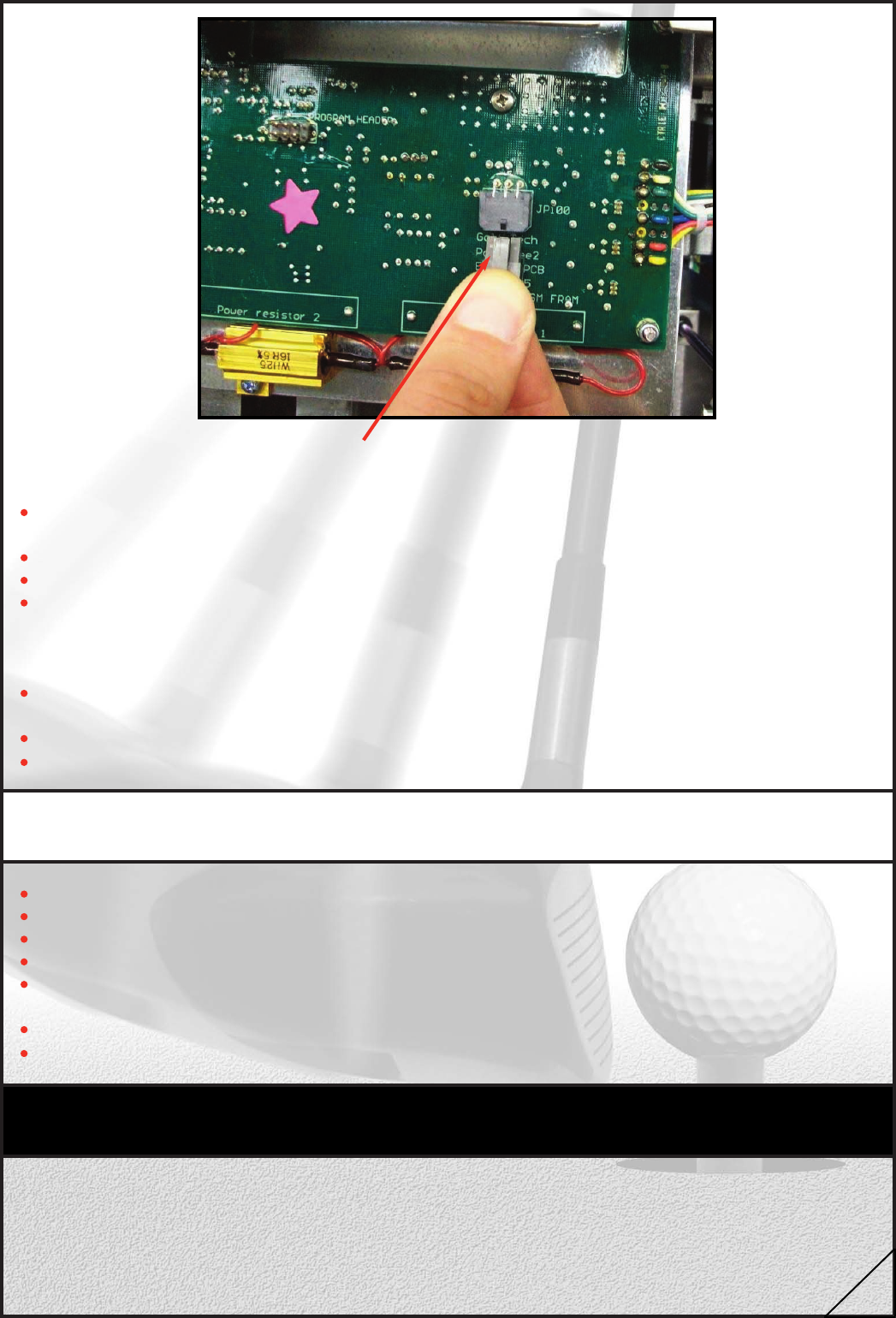
2.5 Power Switch
The power switch is located on the underside of the Control Panel. Operating this switch
disconnects the Power Tee completely from the DC supply. Remaking this switch will
automatically re-initialise the Ball Engine and its controlling software.
5
3 Routine Maintenance
3.1 Water Issues
When a Power Tee is supplied, the hopper is completely sealed to within 50mm of the
surface to which it is fitted. It is therefore possible for the hopper to fill with water. If the
hopper fills to within 120mm of the surface the electronics will become wet and stop
working. Drying the Ball Engine overnight should revive the Ball Engine.
There are three ways for water to enter the machine
1 Rain / surface water
Depending on the height of roof, overhang, prevailing winds and frequency/in
tensity of rain, the amount of water entering the machine through rain
should be no more than a few mm per month, this will give rise to the need
for cleaning out once every 2 months under normal conditions.
2 With the balls supplied
Some ball dispenser / washers supply the balls wet, in this case the amount of
water deposited in each machine will depend on many factors, mainly the
number of uses per day and the amount of water on the balls when they
reach the bay. To get a feel for this input the machines should be regularly
checked in the first two months of operation. Bear in mind that the more
popular bays will take in more water than the quieter bays.
3 From below ground / flooding
In the vast majority of ranges the water table is many metres below the
surface of the range, however if the water table rises to within 50mm of the
range surface, water can flow freely into the machine and flood the Ball
Engine. If this is a rare occurrence on your range, the Ball Engines can be
removed when flood warnings come in and replaced when the range reopens.
If the water table is naturally high but doesn’t come to within 50mm of the
range surface, the hopper will keep the mechanism protected from this type of
ingress.
There are three ways for water to exit the machine
1 Evaporation
Over time, any water entering the system will gradually evaporate.
The rate of evaporation is unlikely to exceed the rate at which water enters the
machines except in the driest hottest periods.
2 Manual removal
The water can be mopped out or vacuumed out at regular times during the
year. This operation must be scheduled and carried out regularly (monthly)
for the first year of operation with the frequency being reduced as the
operator becomes familiar with the water input at that particular site.
3 Drain hole
Although the liner is supplied sealed, it is possible to drill a hole in the liner to
shallow water to drain freely from the liner. Before doing this it is important to be
sure that the water table does not rise high enough to flood the liner from
outside. Units that are damaged due to extended periods submerged in water
are not covered under the warranty.
6
3.2 Daily Maintenance
Tees should be inspected on a daily basis. The Control Panel will flash the top and bottom
tee height simultaneously if the tee is broken. Not all customers will tell the reception if the
tee breaks when they are using it. All staff who are regularly on the range should be briefed
to look out for broken tees when on the range.
3.3 Monthly Maintenance
On a monthly basis, each machine should have the ball tray inspected for foreign
objects and cleaned with a damp cloth. The surrounding trim, hopper lid and the
control panel should be cleaned. Vacuuming the standing mat and the driving mat will
increase the life of the mats.
3.4 Quarterly Maintenance
On a quarterly basis, the Ball Engines should be cleaned, inspected and greased.
NB – ONLY GREASE SUPPLIED BY GOLF-TECH SHOULD BE USED AS IT IS
SPECIFIED FOR THE ENVIRONMENT (CASTROL LMX).
4 Possible Bay Faults
In many cases, re-setting the Power Tee will cure the problem. Turning the machine off does
this via the switch on the underside of the Control Panel and then switching back on again.
4.1 Power Tee dead no display
This is most likely to be the Control Panel, however a damaged cable or
faulty Ball Engine may be short-circuiting the Control Panel. To find the component where
the fault lies is a process of elimination.To avoid damaging your replacement Control Panel,
do not connect the 6 way cable, only connect the two power cables to the switch before
switching on the panel (see below, section 5.4, for instructions on how to change the
Control Panel). The display will read, “Ball Engine not connected”.
Turn off the Control Panel and connect the 6-way connector (this connects the Ball Engine).
Turn on the unit and wait for two seconds. If the display was readable, then the fault was
with the actual control panel. If the display remains blank, the Ball Engine or Ball Engine
cable caused the fault, turn off the Control Panel immediately to avoid damaging it. Change
Ball Engine and repeat. If the display remains blank, replace the ball engine cable (refer to
Section 5.7).
7
4.2 Ball is not automatically replaced after each shot
This fault will be caused by either the microphone or the radar PCB in the Control Panel. To
determine which is the cause of the problem, the Power Tee must be put into set-up mode.
To do this you must:
Press and hold both the tee height and new ball button on the Control Panel.
Switch off power button on underside of Control Panel, wait 2 seconds and
switch back on.
After a few seconds the display will read, “release buttons to select mode”.
Release both the tee height and new ball button simultaneously.
Pressing the tee height button three times will select the set-up mode.
Then press the new ball button to accept this mode.
The lower line of the display will now show two meters.
The meter beginning with “S” is the Speed meter and should respond to a
hand waving across the top of the tee in a motion simulating a golf club
hitting a ball.
If this does not work, the fault lies in the radar module in the Control Panel,
you will need to replace the Control Panel.
The meter beginning with “M” is a Microphone meter and should respond to a
clap near the Control Panel or a light tap on the lower half of the Control
Panel enclosure. If the meter does not respond, you will need to replace the
Control Panel.
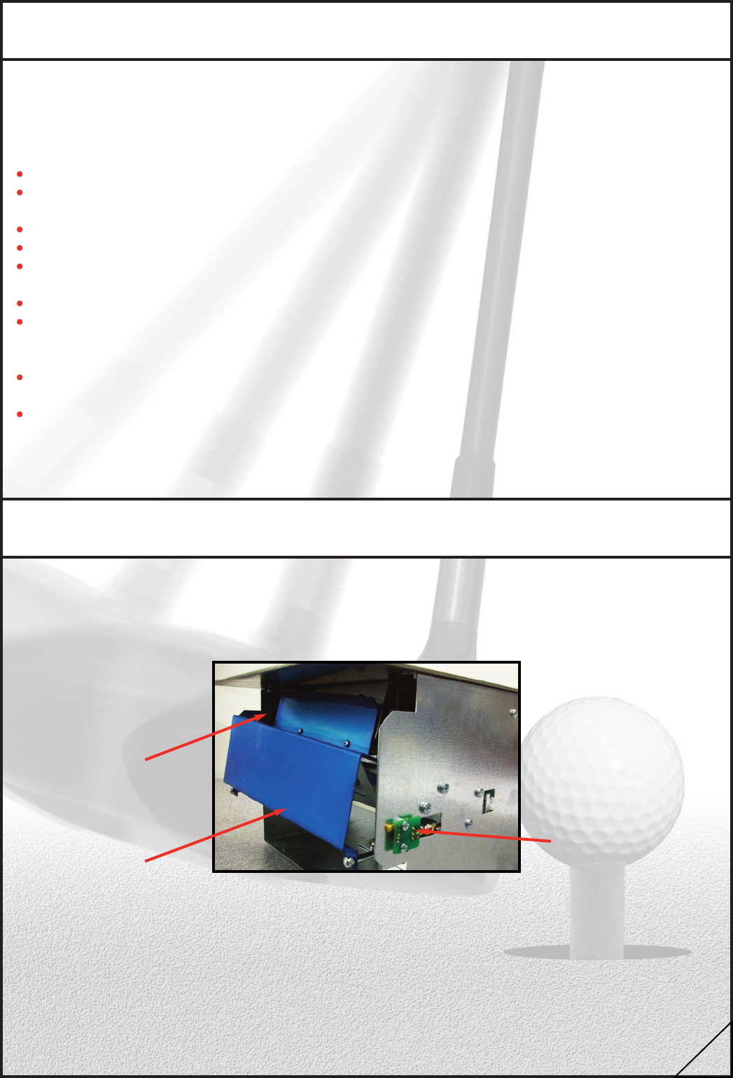
4.3 Power Tee does not start when balls poured into hopper
This is caused by a problem with the ball in hopper detectors, remove the Ball
Engine and inspect the optics for dirt and debris.
If there is no obvious fault, the spare Ball Engine should be fitted and the faulty Ball Engine
returned to the factory for repair.
Optics
Optics on scoop side
Scoop
8
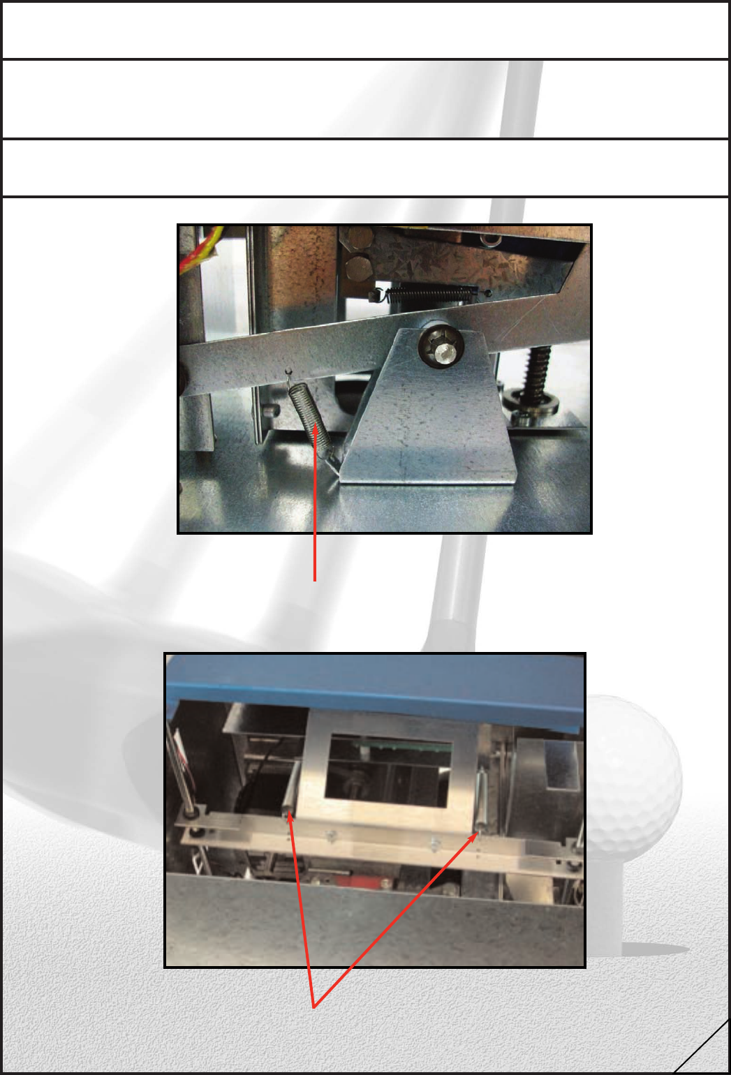
4.4 Balls do not feed from hopper to tee
Ensure that balls are not stacked up on top of the scoop. Once all balls are removed from
the hopper and scoop, reset the machine. If the fault persists remove the Ball Engine and
check the injector spring and scoop springs. If the fault persists exchange the Ball Engine.
4.5 Broken springs
Replace injector spring if broken
Replace scoop spring if broken
9
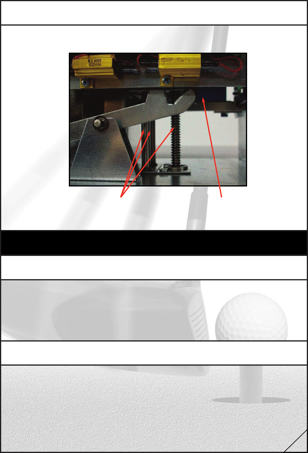
4.6 Machine is noisy as tee lowers
If the machine is making a “chattering” noise as the tee lowers, this normally
indicates that the lead screw and/or guide bearing bars require lubrication.
Carriage
Grease the lead screw and the
two bearing bars above and
below the carriage
5 Maintenance procedures
5.1 Tee change
Cycle the Power Tee into the up position by dropping a ball into the hole where the ball
normally emerges and pressing the new ball button. When the tee is in the up position,
select the top tee height and use the tool provided to remove the damaged tee. Drop the
tee fixing bolt into a new tee and refit. If the damaged tee is stuck in the mechanism,
select the lowest tee height and use a screw driver to straighten the damaged tee so that
the tee fixing bolt can be removed. Drop the tee fixing bolt into a new tee and refit.
5.2 Reset Power Tee
To reset the Power Tee, switch the power button on underside of Control Panel, wait 2
seconds then switch back on, the machine will initialise. After initialisation the Control Panel
will display a “TRAVEL” reading. The travel must be between 101mm and 105mm. If the
travel is less than this there may be a mechanical fault or a foreign object in the Ball
Engine restricting the movement.
10
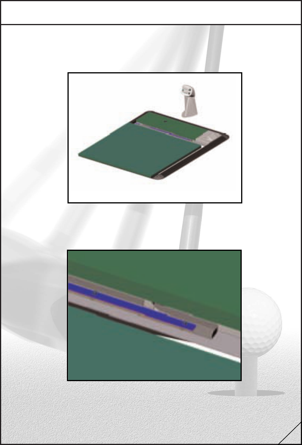
5.3 Driving Mat removal and fitting
Lift the edge of the standing mat furthest from the driving mat and pull away from the
driving mat by about 6”.
Slide the mat clamp to the right and lift the near
edge of the driving mat.
Lay the mat to one side ensuring that it is in a
safe place where people will not trip on it.
Removal
11
Ensure that the metal lugs on the metal rails have not been damaged. If the mat was not
fitted properly the lugs may be “bent” out of position. If there is any
damage, use a reasonable size pair of pliers and bend the lugs back into position.
Place the mat in position ready for refitting at approximately 45 degrees to the ground.
Slide the mat away from you ensuring that all of
the lugs locate properly under their loops.
Lower the mat into position while holding
the mat clamp to the right. When the mat is
firmly in place, release the mat clamp.
Refittng
12
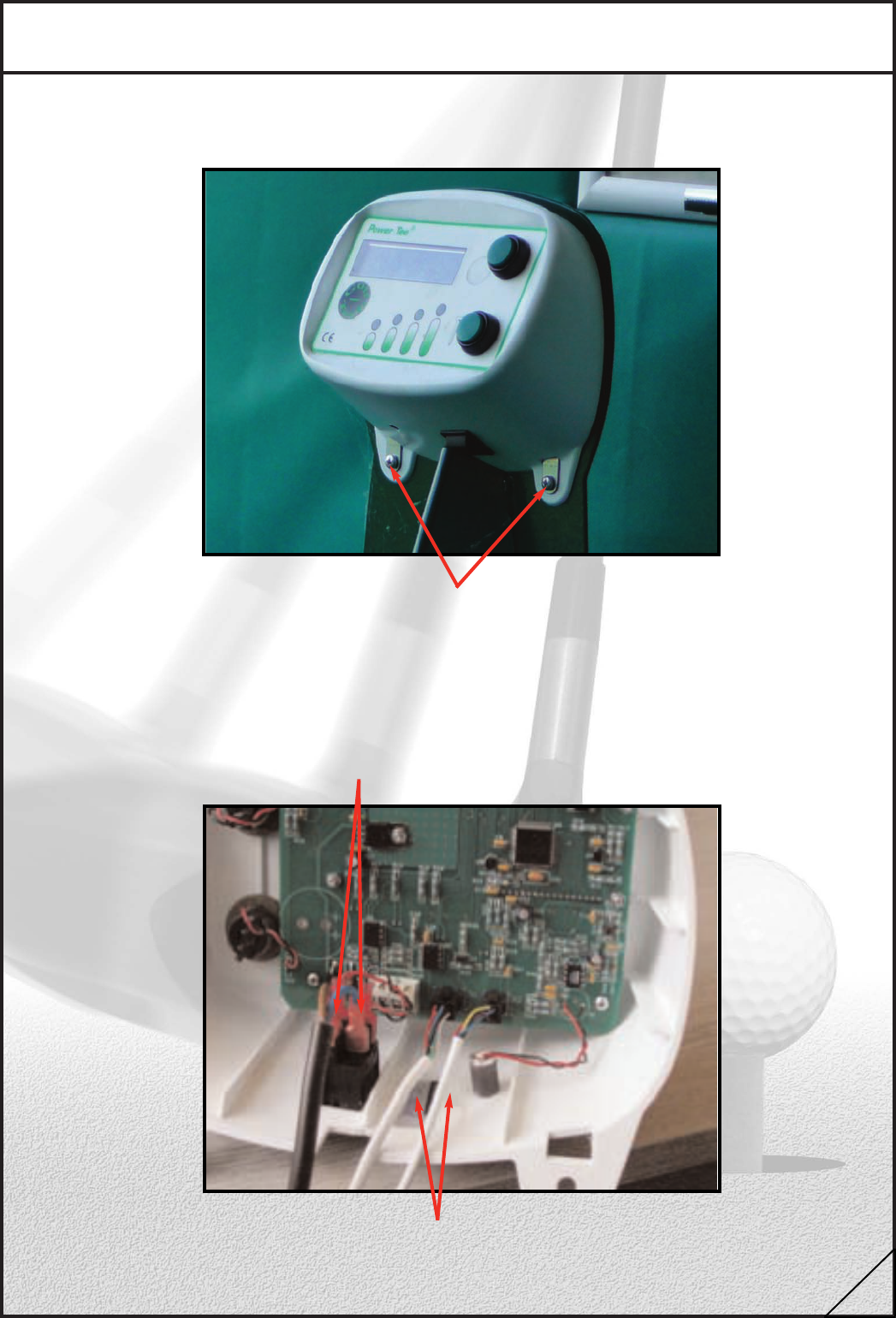
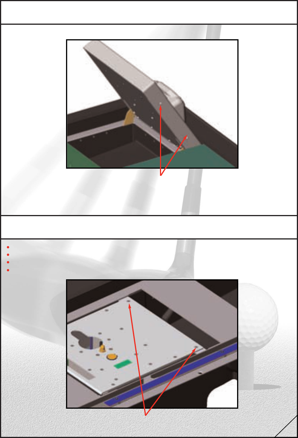
5.4 Control panel change
Switch off the power to the bay via the switch on the underside of the Control Panel
Undo the two lower retaining screws.
Undo these two screws
Ensure that the metal lugs on the metal rails have not been damaged. If the mat was not
fitted properly the lugs may be “bent” out of position. If there is any
damage, use a reasonable size pair of pliers and bend the lugs back into position.
Place the mat in position ready for refitting at approximately 45 degrees to the ground.
First disconnect the two power connectors
Then disconnect the six way cable
To refit the new panel, reverse the procedure.
13
5.5 Replacing hopper lid
Open the Hopper Lid and remove the four cover retaining screws.
Remove two screws from each side using the
allen key supplied.
Lower the lid and lift off the cover. To refit the hopper lid, press new cover onto hopper lid
when lid is closed and replace screws.
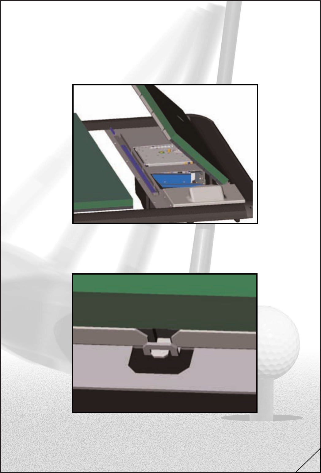
5.6 Ball engine change
Switch off Power Tee at the Control Panel.
Remove the Driving Mat as described above (section 5.3).
Remove any balls or foreign objects from hopper.
Remove the two retaining screws.
Remove these two screws only
Carefully lift out the Ball Engine and place on the first hopper brace. 14
Disconnect cable, taking care to press in the
locking lug before pulling connector.
Set faulty Ball Engine to one side and take opportunity to clean out any
foreign objects from inside the hopper base.
Place new Ball Engine on the first hopper brace.
Reconnect the cable.
Lower the new Ball Engine into place.
BE CAREFUL NOT TO TRAP THE CABLE BETWEEN THE BALL ENGINE
TOP PLATE AND REAR SUPPORT STUDS.
IMPORTANT - Refit retaining screws.
Replace driving mat.
Switch on Power Tee and check travel is between 101 and 105mm.
5.7 Ball Engine Cable (6 way connector)
Remove Control Panel and Ball Engine. (See above for details).
Tie string around the Ball Engine cable in liner.
Tape over the join to prevent snagging.
Pull the cable through the conduit drawing the string behind.
Attach cable to the string in a similar way and pull back into place using
the string.
Replace any cable ties.
Replace Ball Engine and Control Panel.
6 DC Power supply
Each bay is fed approx. 28V DC from a switch mode 110-240V mains power supply. The
number of Power Tees installed will govern the size and number of Power
Supply Unit(s).
15
7 Software Diagnostics
Each bay is fed approx. 28V DC from a switch mode 110-240V mains power supply. The
number of Power Tees installed will govern the size and number of Power
Supply Unit(s).
To enter software diagnostics, press and hold both the tee height and new ball
buttons on the Control Panel.Switch the power button on underside of Control Panel, wait
2 seconds then switch back on. After a few seconds the display will read,
“release buttons to select mode”. Release both the tee height and new ball button
simultaneously. Pressing the “tee height” button will cycle through the various
diagnostic modes.
Display will default to:
Min tee
height LED
Max tee
height LED
Tee height button
NORMAL Accept
Change
New Ball Button
Press the tee height button to cycle through the four modes:
Mode 1 - Normal
Mode 2 - Nudge
Mode 3 - Auto
Mode 4 - Set-up
Mode 1 Normal
Same setting for normal start up
Mode 2 Nudge
Accept the nudge mode by pressing the “new ball” button. The Ball Engine will go through
the start up sequence to set min and max travel.
Pressing the “new ball” button raises the tee and pressing the “tee height” button lowers
the tee.The top left display will show the travel in millimetres.
16
The bottom left will display “C T H ”. These are the optic sensor diagnostics. As the tee
moves up and down, the optic beams will be blocked and the characters will show. When
the beam is not blocked, the display will only show a “dash”.
The “C” sensor is the carriage position sensor. This is the main sensor that the
machine relies on to set the initial min and max travel.
The “T” sensor informs the machine whether the tee is present or whether there is a ball
still on the tee when cycling to feed a new ball, this sometimes happens when a person
presses the button for a new ball when a ball is already on the tee.
If there is no tee present, the minimum and maximum tee height LED’s will flash
(in normal mode only).
The “H” sensor informs the machine that there is a ball on the scoop that is fed
directly from the hopper. This is the sensor that starts the cycle when the golfer pours the
balls into the hopper.
If any of the sensors are faulty, the display will only show the dash character when the
beam is interrupted. The Ball Engine will have to be returned to Golf-Tech for base repairs.
Mode 3 Auto
This mode is for in-house testing. The engine undergoes comprehensive testing to ensure
correct build. Not to be used on site for normal usage or fault finding.
Mode 4 Set-Up
Cycles through the following:
---------- BAY
¦
¦---- ADDRESS
¦
¦---- MIN T HEIGHT
¦
¦---- MAX T HEIGHT
¦
¦---- BALL COUNT
Bay - Balls served by this display unit
Address - Communications address for display (usually the bay no)
Min T Height - Lowest tee height default = 3 (range 2 – 12mm)
Max T Height - Highest tee height default = 38 (range 26 – 38mm)
Ball Count - ON/OFF
8 Switching Power Tee on/restarting/resetting
Each individual bay has a delay system built in to ensure that when the system is switched
on not all the bays start together causing a temporary overload in the power supply unit.
When switching on an individual bay, holding the “tee height button” and then switching the
control panel on will overcome this countdown delay.
17