Goliath Solutions SPIDER-10-003 Goliath Solutions Spider III RFID System User Manual
Goliath Solutions Goliath Solutions Spider III RFID System Users Manual
Contents
- 1. Manual Part 1
- 2. Manual Part 3
- 3. Users Manual
Users Manual

Walgreens Installation Guide
G-1-2002-2B
5/27/2008

Walgreens Installation Guide
G-1-2002-2B
Walgreens Installation Guide 2B.doc
Use or disclosure of this document is covered under the Non-Disclosure Agreement executed between the reader and Goliath Solutions,
LLC. This document and the information contained herein are privileged and should only be viewed by expressly authorized parties.
5/27/2008 Page: ii
Table of Contents
CHAPTER 1 - INTRODUCTION:.............................................................................. 1-1
Reminder:......................................................................................................................... 1-1
Prior to Installation:........................................................................................................... 1-1
Ceiling Tiles:..................................................................................................................... 1-2
Work Orders:.................................................................................................................... 1-2
Walgreens Environment: .................................................................................................. 1-3
CHAPTER 2 - STORE INSTALLATION PROCEDURES: ....................................... 2-1
Check-In:.......................................................................................................................... 2-1
Pre-Installation Store Survey:........................................................................................... 2-2
Introduction: ...................................................................................................................................2-2
Potential Installation Issues: ..........................................................................................................2-3
Estimating Cable Lengths: .............................................................................................................2-4
Validate the Store Floor Plan: ........................................................................................................2-5
Determine if Power is available for the MEU by the Front Security Screen: .................................2-5
Determine CMU Installation Location: ...........................................................................................2-5
Determine the Primary MEU Installation Location: ......................................................................2-16
Determine if a Second MEU is required: .....................................................................................2-20
Determine the Tx/ATA and Rx/ARA Antennae Placement: .........................................................2-21
Determine the Cable Pulls: ..........................................................................................................2-24
Pre-Installation Store Survey Check Off Form.............................................................................2-25
Installation:..................................................................................................................... 2-26
Installation Prep: ..........................................................................................................................2-27
CMU Installation:..........................................................................................................................2-30
Cable Pulls: ..................................................................................................................................2-36
Cable Installation Requirements:.............................................................................................2-38
Cable Pull Procedure:..............................................................................................................2-39
Correct Cable Installations: .....................................................................................................2-43
In-Correct Cable Installations (Violations): ..............................................................................2-44
CMU/MEU Power Cable: .........................................................................................................2-46
Tx/ATA Installation:......................................................................................................................2-48
Installation of the Transmitter antennae (Tx/ATA) in the store:...............................................2-48
Installation of the Transmitters (Tx/ATA) over the Sales Floor: ..............................................2-49
Installation of the Tx/ATA antenna in the Stock Room:...........................................................2-51
Correct Tx/ATA Installation in Stock Room: ............................................................................2-51
In-Correct Tx/ATA Installation Stock Room (Violations): ........................................................2-52
Rx/ARA Installation: .....................................................................................................................2-53
Installation of the Receiver antennae (Rx/ARA) over the Sales Floor: ...................................2-53
Installation of the Rx/ARA over the Sales Floor: .....................................................................2-54
Installation of Rx/ARA Antennae in the Stock Room: .............................................................2-56
Correct Rx/ARA Installation in Stock Room: ...........................................................................2-57
In-Correct Tx/ATA Installation in Stock Room (Violations):.....................................................2-58
MEU Installation at Permanent Location: ....................................................................................2-59
Post Mount Procedures: ..........................................................................................................2-61

Walgreens Installation Guide
G-1-2002-2B
Walgreens Installation Guide 2B.doc
Use or disclosure of this document is covered under the Non-Disclosure Agreement executed between the reader and Goliath Solutions,
LLC. This document and the information contained herein are privileged and should only be viewed by expressly authorized parties.
5/27/2008 Page: iii
Suspended Mount Procedures: ...............................................................................................2-62
Wall Mounted Procedures: ......................................................................................................2-64
Exception Stores:.........................................................................................................................2-67
Sheet Rock or Wood Ceilings..................................................................................................2-67
Examples of Sheet Rock Ceiling Installation: .....................................................................2-67
Examples of Wood Ceiling Installation:...............................................................................2-69
Concrete Ceilings: ...................................................................................................................2-71
Ramset Safety:....................................................................................................................2-71
Example 1 – Concrete Ceiling (Cables Suspended from Wires): .......................................2-72
Example 2 – Concrete Ceiling (J hooks installed with a Ramset): .....................................2-74
Example 3 – Concrete Ceiling – Stock Room (J hooks installed with a Ramset):..............2-75
CHAPTER 3 - INSTALLATION COMPLETION: ...................................................... 3-1
Installation Completion: .................................................................................................... 3-1
Documenting the Store Installation: ...............................................................................................3-1
Store Check-out: ............................................................................................................................3-2
Upon Completion of Successful System Test: ..........................................................................3-2
If there is an unsuccessful system test:.....................................................................................3-3
Quality Assurance Survey: ............................................................................................... 3-4
APPENDIX A - Antenna Placement........................................................................ A-1
Introduction ......................................................................................................................A-1
Glossary .........................................................................................................................................A-1
Antenna Placement: .........................................................................................................A-4
Description of Hardware ................................................................................................................A-4
Antenna Placement within the Walgreens Environment................................................................A-5
Sample Rx/ARA Locations ........................................................................................................A-5
Sample Tx/ATA Locations 9 Aisle Store ...................................................................................A-7
Antennae Placement Issues over the Sales Floor ....................................................................A-8
Transmitter Placement over Sales Floor .....................................................................................A-11
Receiver Placement over Sales Floor .........................................................................................A-12
Back Wall Rx/ARA Antennae Placement Issues (Rx-9, Rx-10, Rx-11 and Rx-12).................A-15
Rx-14 (only required in stores with the new Corner Pharmacy layout) ...................................A-16
Stock Room Antenna Placement.................................................................................................A-17
Stock Room Antenna Placement Issues .................................................................................A-18
Antenna Placement Exceptions......................................................................................A-19
Expanded Cosmetics Department ...............................................................................................A-19
Non-Standard Stock Room Configurations..................................................................................A-20
APPENDIX B - Support Documents....................................................................... B-1
Standard Installation Kit Contents:....................................................................................B-1
Hot Spare Kit:...................................................................................................................B-2
Minimum Tools and Materials Required for Installation:....................................................B-6
Sample Store Data Sheet:................................................................................................B-7
CIT Installation Checklist: .................................................................................................B-8
GOLIATH QA Checklist ..................................................................................................B-10
Best Practices Do’s and Don’ts: .....................................................................................B-12
Walgreens Installation Guide
G-1-2002-2B
Walgreens Installation Guide 2B.doc
Use or disclosure of this document is covered under the Non-Disclosure Agreement executed between the reader and Goliath Solutions,
LLC. This document and the information contained herein are privileged and should only be viewed by expressly authorized parties.
5/27/2008 Page: iv
Store Data Form:............................................................................................................B-13
Installation Exception Form:.........................................................................................................B-14
Store Cable Length Form:............................................................................................................B-15
Pre-Installation Survey Checklist: ...................................................................................B-16
Ramset Warning Sign:....................................................................................................B-21
Revision Record
Document
Title:
Walgreens Installation Guide
Revision Page(s)
Number
Remarks
2.0 -4/28/08 All Revised for the CMU and MEU III.
2A – 5/13/08
5/15/2008
1-3
2-7, 2-8
2-8, 2-9
2-42
2-57, 2-59
2-17, 2-44,
2-49
B-2
B-13
B-14
B-16
All
2-7 to 2-9
2-44
B-2
B-13
Walgreens Environment page added
Example of a 48 port switch added
Example of two 24 port switched added
Goliath grid label to mark location of MEU power in
ceiling.
Goliath grid label to mark location of MEU.
ATA/ARA added
Updated contents and quantities of the Hot spare kit.
Updated Store Data Form to reflect QB entries.
Added Installation Exception for to lists quantities for
OBF, Shortages/Overages, Hot Spare Usage
Add do not enter pharmacy to Pre-installation Survey
checklist.
Replace all references of Tx and Rx in the document
with Tx/ATA and Rx/ARA.
Stock images and explanation of 24 and 48 port
switches.
Instructions added for revision D, J and 3 of Tx/ATA
List 1 box for drywall screws and 1 box for 1” mounting
bases for the Hot Spare Kit.
Add comment on Store Data Form item 13 and record
revision level for each Tx//ATA and location.
Walgreens Installation Guide
G-1-2002-2B
Walgreens Installation Guide 2B.doc
Use or disclosure of this document is covered under the Non-Disclosure Agreement executed between the reader and Goliath Solutions,
LLC. This document and the information contained herein are privileged and should only be viewed by expressly authorized parties.
5/27/2008 Page: v
Document
Title:
Walgreens Installation Guide
Revision Page(s)
Number
Remarks
2B - 5/27/2008
6/11/2008
2-1
1-3
1-3, 2-2,
2-14, 2-16,
B-16
2-3
2-5
2-7, 2-8,
2-9
2-12
2-13
2-16
2-30
2-32
2-33, 2-34,
2-35
2-67 thru
2-75
2-67
B-2 thru
B-5
B-21
vi
Update Help Desk phone number to 207-591-1583
Add contact Help desk immediately if an accident
occurs during the store installation.
Update access to Pharmacy Policy.
Wood and sheet rock Ceiling added to issues.
Add to pre-installation survey check if power available
by front security screen before surveying CMU
location. Add Managers office to Catalina location
Change item 2 in pre-installation survey to define CMU
installation in the Pharmacy instead of the Managers
Office.
Add verbiage describing switch 2.
Add verbiage to picture to indentify daisy chain cable.
Update sub-bullets to refer to Catalina and
communication cabinet instead of just Catalina Cabinet
(bullet 2).
Update picture with installed CMU with clips.
Add Installed CMU picture.
Update CMU installation for Pharmacy
Update Sheet Rock, Wood and Concrete ceiling.
Add recommendation to use 2 cordless drills for wood
ceilings.
Updated Hot Spare kit with pictures.
Ramset sign added.
FCC Compliance note added.

Walgreens Installation Guide
G-1-2002-2B
Walgreens Installation Guide 2B.doc
Use or disclosure of this document is covered under the Non-Disclosure Agreement executed between the reader and Goliath Solutions,
LLC. This document and the information contained herein are privileged and should only be viewed by expressly authorized parties.
5/27/2008 Page: vi
Note: This equipment has been tested and found to comply with the limits for a Class B digital device,
pursuant to part 15 of the FCC Rules. These limits are designed to provide reasonable
protection against harmful interference in a residential installation. This equipment generates
uses and can radiate radio frequency energy and, if not installed and used in accordance with
the instructions, may cause harmful interference to radio communications. However, there is no
guarantee that interference will not occur in a particular installation. If this equipment does
cause harmful interference to radio or television reception, which can be determined by turning
the equipment off and on, the user is encouraged to try to correct the interference by one or
more of the following measures:
Reorient or relocate the receiving antenna.
Increase the separation between the equipment and receiver.
Connect the equipment into an outlet on a circuit different from that to which the receiver is
connected.
Consult the dealer or an experienced radio/TV technician for help

Walgreens Installation Guide
G-1-2002-2B
Walgreens Installation Guide 2B.doc
Use or disclosure of this document is covered under the Non-Disclosure Agreement executed between the reader and Goliath Solutions,
LLC. This document and the information contained herein are privileged and should only be viewed by expressly authorized parties.
5/27/2008 Page: 1-1
Chapter 1 - INTRODUCTION:
The Walgreens Installation Guide (G-1-2002) defines the standard installation processes
and requirements for the installation of the Goliath Solutions System in the Walgreens
environment. Walgreens stores will be installed by a contracted Cable Installation Team
(CIT). The target audience for this manual is the CIT and the Goliath Solutions Help Desk
(Help Desk).
This document will provide a best practices guide for the installation, suggested workflows
and the minimum acceptable standards for the installation.
Two other guides are referenced in this document. These guides along with this guide
comprise the Walgreens Installation Manual (G-1-1000). The Walgreens Installation
Manual documents the complete installation processes and standards for installation of
the GOLIATH System at Walgreens. The other guides are:
Introduction to Store Installation Processes Guide (G-1-2001)
Walgreens Store Floor Plan Reference Guide (G-1-2003)
Reminder:
Throughout the installation you will be working in areas of the store that customers and the
employees need to access. Always be aware of the space you occupy, and limit the need
for tools and material to be in the aisles where customers are shopping and employees
are working. Be especially careful as any cables that are strewn about the aisles are a
hazard to customers, employees and the CIT.
Please be polite and helpful to the Retailer’s employees and customers when you
are at the store. If asked for assistance by a customer, please kindly refer them to
store personnel or find store personnel to help customer.
Prior to Installation:
GOLIATH will ship the Installation Kit to the store. The hardware will be at the store one
day prior to the planned installation date. The CIT will contact the Store Manager or the
Executive Assistant Manager approximately seventy-two hours prior to any planned
installation activity and make every effort to accommodate the store’s expectations
regarding the installation, which may include swapping with nearby stores to
accommodate shipments and inventory counts. It is also recommended that the CIT Lead
Tech call the store twenty-four hours prior to the installation to accommodate any last-
minute circumstances. Any changes to the schedule must by approved by the Help Desk.

Walgreens Installation Guide
G-1-2002-2B
Walgreens Installation Guide 2B.doc
Use or disclosure of this document is covered under the Non-Disclosure Agreement executed between the reader and Goliath Solutions,
LLC. This document and the information contained herein are privileged and should only be viewed by expressly authorized parties.
5/27/2008 Page: 1-2
Ceiling Tiles:
During the survey and installation you will be handling ceiling tiles in your work area. Be
careful when removing and replacing the ceiling tiles so you do not damage or mark the
ceiling tiles. Make sure your hands are clean and free of debris when handling
ceiling tiles. Always remove the ceiling tile when you are standing on a ladder, never use
a pole to remove a ceiling tile.
If a ceiling tile is damaged or broken during the installation process, notify the Store
Management. Many times the store will have extra ceiling tiles and you can simply
replace the damaged tile with a new tile. If the store does not have any extra ceiling tiles,
the CIT will replace the tile during a revisit before the end of the week. If a damaged
ceiling tile could be a potential hazard to anyone on the floor do not reinstall it!
If you damage any ceiling tiles during the installation process update the Help Desk during
your store check-out call. The Help Desk will need to know the following information:
The location of the damaged ceiling tile.
If the damaged tile was replaced during the installation.
Is the ceiling is open because the damaged tile was not replaced during the install.
Will the ceiling tile need to be replaced by the CIT during a revisit.
If a revisit is required, the scheduled revisit date. (The revisit should occur before
the end of the current work week)
Work Orders:
The Cable Installation Vendor (CIV) will provide the CIT with a work order and a floor plan
of the store for the installation. The floor plan will show the designated locations for the
Goliath equipment. The work order should include but is not limited to the following
information:
Store number
Store address
Store contact information
Scheduled Installation date
Store floor plan
Warehouse delivery days
The Help Desk may provide additional information needed for the installation when you
check-in with them.

Walgreens Installation Guide
G-1-2002-2B
Walgreens Installation Guide 2B.doc
Use or disclosure of this document is covered under the Non-Disclosure Agreement executed between the reader and Goliath Solutions,
LLC. This document and the information contained herein are privileged and should only be viewed by expressly authorized parties.
5/27/2008 Page: 1-3
Walgreens Environment:
The installation is taking place in a live store environment with employees and customers.
The CIT must at all times be aware of this environment. Goliath Solutions and the CIT are
guests of Walgreens and must follow Walgreens vendor policies. The following items are
a summary of those policies.
Always be polite to store employees and customers.
Follow store safety procedures.
Follow industry safety procedures.
Follow the Goliath safety procedures that are documented in the Introduction to
Store Installation Processes Guide. If an accident should occur during a
store installation, then contact the Goliath Help Desk Immediately.
Business casual is the required clothing for the CIT during the install. The CIT
should follow these rules regarding dress attire:
oWear cotton or denim slacks.
oNever wear shorts.
oAlways wear the appropriate footwear (work boots, sneakers, etc.) required for
working on a ladder.
Food or beverages may be purchased by the CIT during the install, but the CIT
must obey the following policies:
oThe item must be purchased prior to consuming it.
oOnly eat food in the store break room or outside the store.
oNon-alcoholic beverages can be consumed in the store while the CIT is
working. The Walgreens receipt must be taped to the beverage. The sales
clerk will tape the receipt on the beverage container when requested.
Access to some areas of the store may be restricted.
oStore management may require that a store employee is with the CIT in some
areas of the store, such as the Managers Office or the Pharmacy.
oOnly Enter the Pharmacy if all of the following
conditions are true in the store:
There is no Catalina Cabinet in the store and the network switch is
located in the pharmacy.
The highest available level of store management is aware that the CIT
needs access to Pharmacy.
The CIT must be accompanied by a Registered Pharmacist that
is on duty, at all times when working in the Pharmacy. A
Pharmacist is the only Walgreens employee that is allowed to
escort the CIT while in the Pharmacy.

Walgreens Installation Guide
G-1-2002-2B
Walgreens Installation Guide 2B.doc
Use or disclosure of this document is covered under the Non-Disclosure Agreement executed between the reader and Goliath Solutions,
LLC. This document and the information contained herein are privileged and should only be viewed by expressly authorized parties.
5/27/2008 Page: 2-1
Chapter 2 - STORE INSTALLATION PROCEDURES:
Check-In:
Morning installations start at 8 AM local time.
Upon arrival, the following tasks must be completed:
1) Locate the highest available level of Store Management (the Store Manager’s
name is posted near the front door).
The Lead Tech must introduce himself and the crew.
Explain the installation process of the receivers and transmitters, the
approximate amount of time the install will take, and the areas of the store that
will require access. Do not attempt to answer any questions on the operation
of the system. Please refer any questions to the Customer Services Help Desk
listed in the Welcome Package.
Ask the store manager if they know the location of the secondary
communications cabinet (Catalina cabinet).
Locate the Installation Kit that has arrived at the store.
oRetrieve the Welcome Package from the Installation Kit.
oRecord the serial numbers of the CMU and MEU(s).
Give the Store Manager the Welcome Package from the kit. This will give them
a point-of-contact for their store and some information on how the system
works.
Photo I.D. must be displayed by all members of the crew at all times.
2) After completing the check-in process with the store, then bring the ladders into the
store. The Lead Tech should perform the Pre-installation Survey while the second
tech brings in the rest of the installation equipment and then starts the installation
prep.
3) Call the Goliath Solutions Help Desk at 207-591-1583 to check-in immediately
after the completion of the Pre-installation survey. Provide the Help Desk with the
following information:
Arrival time at the store.
Names of the install team and the cell phone number of the CIT Lead Tech.
The CMU and MEU serial numbers.
Serial numbers of the CMU and MEU.
Any issues found during the survey that will affect the installation.
All installations require a check-in and check-out call with the Help Desk. If needed
during the installation, call the Help Desk to resolve installation issues.

Walgreens Installation Guide
G-1-2002-2B
Walgreens Installation Guide 2B.doc
Use or disclosure of this document is covered under the Non-Disclosure Agreement executed between the reader and Goliath Solutions,
LLC. This document and the information contained herein are privileged and should only be viewed by expressly authorized parties.
5/27/2008 Page: 2-2
Pre-Installation Store Survey:
Introduction:
Using the provided store floor plan and the Pre-installation Survey Checklist (located
In Appendix B – Support Documents) perform the Pre-installation Store Survey. The
survey will determine the actual location of the Goliath equipment, any exception issues
with the installation and the path of the cable pulls. Reference “Chapter 2” and
“Appendix A - Antenna Placement” of this guide for detailed survey and installation
instructions. If the store floor plan has not been provided, contact the Help Desk for
further instructions.
The store floor plan has been customized for each store to provide the recommended
location for the CMU, MEU, Tx/ATA antennas and Rx/ARA antennas. The actual location
may need to be adjusted if issues with the recommended location are found during the
Pre-installation Store Survey.
During the Pre-installation Store Survey and the installation you will be collecting data
about the installation that the Help Desk will require during your check-in and check-out
calls. Record the survey data on the Store Data Form (located In Appendix B – Support
Documents). This form lists all the data you will need to collect during the installation.
You will need to provide this data verbally to the Help Desk during either your check-in or
check-out call.
Remember, the Pre-installation Store Survey is the key to a successful and
efficient store installation.
Only Enter the Pharmacy under all of the following conditions:
There is no Catalina Cabinet in the store and the network switch is
located in the Pharmacy.
The highest available level of store management is aware that the CIT
needs access to Pharmacy.
The CIT must be accompanied by a Registered Pharmacist that is on
duty, at all times when working in the Pharmacy. A Pharmacist is the
only Walgreens employee that is allowed to escort the CIT while in the
Pharmacy.
Minimize the time spent working in the Pharmacy.

Walgreens Installation Guide
G-1-2002-2B
Walgreens Installation Guide 2B.doc
Use or disclosure of this document is covered under the Non-Disclosure Agreement executed between the reader and Goliath Solutions,
LLC. This document and the information contained herein are privileged and should only be viewed by expressly authorized parties.
5/27/2008 Page: 2-3
During the Pre-Installation Survey the following information will be determined:
1) Validate that the provided store floor plan is correct.
2) Validate if power is available by the front security screen for the MEU.
3) Location and power source for the CMU.
4) Location, power source and the mounting method for the MEU.
5) Access point into the stock room for cables.
6) If a second MEU will be required.
7) The actual location for each Tx/ATA and Rx/ARA antennae.
8) The cable lengths required for each Tx/ATA and Rx/ARA antennae.
9) The sequence and order of each cable pulls.
10) The ceiling height and height of roof girders above ceiling.
11) Potential installation issues.
Do not contact the Help Desk until the completion of the Pre-installation
Store Survey unless the provided floor plan is incorrect.
Potential Installation Issues:
If any of the following conditions are present, contact the Help Desk at the completion of
the Pre-installation survey! These issues include, but are not limited to:
Missing installation kit.
Missing welcome letter for Store Manager
Incomplete installation kit
Damaged installation kit
Concrete ceilings requiring special tools for installation.
Wood ceiling.
Sheet rock ceilings.
Girder height in excess of 25 feet.
No roof iron present in the ceiling.
Walgreens Installation Guide
G-1-2002-2B
Walgreens Installation Guide 2B.doc
Use or disclosure of this document is covered under the Non-Disclosure Agreement executed between the reader and Goliath Solutions,
LLC. This document and the information contained herein are privileged and should only be viewed by expressly authorized parties.
5/27/2008 Page: 2-4
Estimating Cable Lengths:
During the survey you will be estimating the distances between the GOLIATH antennas
(TX/ATA and Rx/ARA) and the MEU to determine what length of cables to use for each
antenna. You must also verify that distance does not exceed the maximum supported
cable lengths listed below.
Maximum supported cable lengths from the MEU
Power Source 110 foot
Tx/ATA Antennae 110 foot
Rx/ARA Antennae 135 foot
Estimate the distances using any method you prefer. Remember to allow for additional
cable length to go from the roof girders to the Goliath Hardware and enough cable length
to form minimal service loops. Two methods that have been successfully used to estimate
the distances are:
Walking the floor using a Measuring Wheel.
Counting Ceiling Tiles. Most stores use 2 foot by 4 foot ceiling tiles. By counting
the number of tiles between locations you can estimate distances.
Coaxial cable lengths are 25 foot, 50 foot, 85 foot and 110 foot in the installation kit. Use
the appropriate length cable for each Tx/ATA and Rx/ARA. Extra 85 foot cables are
provided in the Hot Spare Kit. The 85 foot cables can be substituted for the 110 foot
cables during the installation if the shorter cables can be used.
Walgreens Installation Guide
G-1-2002-2B
Walgreens Installation Guide 2B.doc
Use or disclosure of this document is covered under the Non-Disclosure Agreement executed between the reader and Goliath Solutions,
LLC. This document and the information contained herein are privileged and should only be viewed by expressly authorized parties.
5/27/2008 Page: 2-5
Validate the Store Floor Plan:
The first step in the pre-installation store survey is to validate that the provided store floor
plan is correct and matches the actual store floor plan. If the store floor plan is not
correct; go to the Floor Plan Questions section found in the “Walgreens Store Floor
Plan Reference Guide”. Gather the information asked in these questions and then
contact the Help Desk. The Help Desk will then help determine the actual floor plan.
Determine if Power is available for the MEU by the Front Security Screen:
The power source for the MEU must be an open uninterrupted 24-hour power source. It can
not be plugged into a cube tap, power strip or a UPS used by a LAN cabinet or computer.
Check power at this location prior surveying the CMU location.
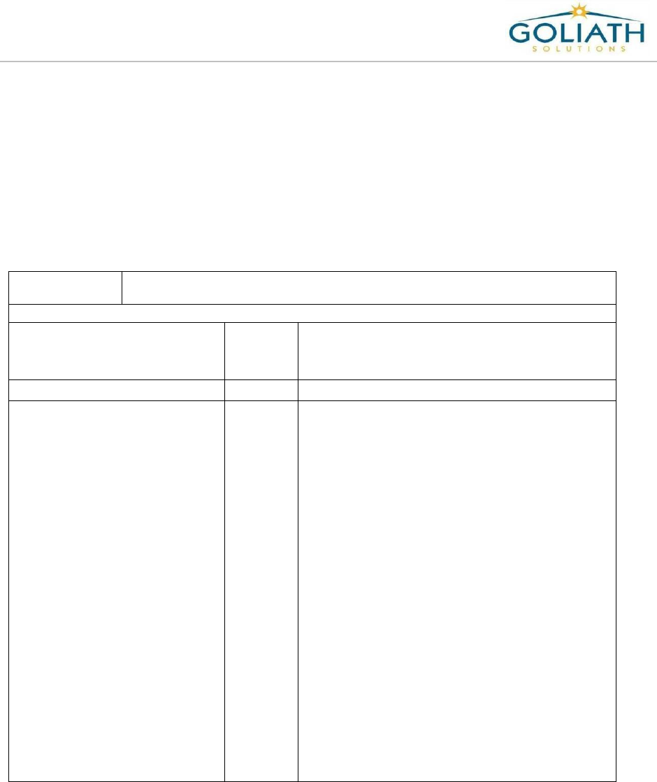
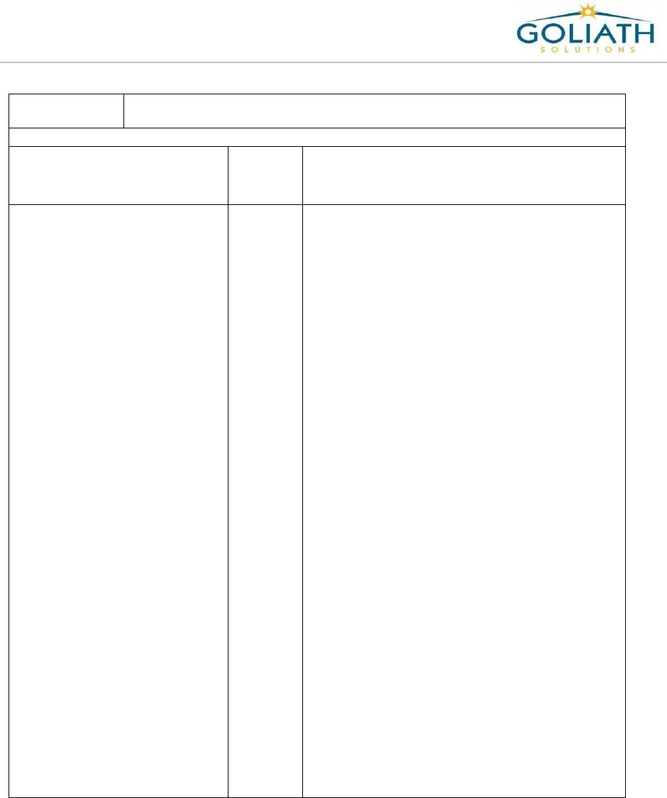
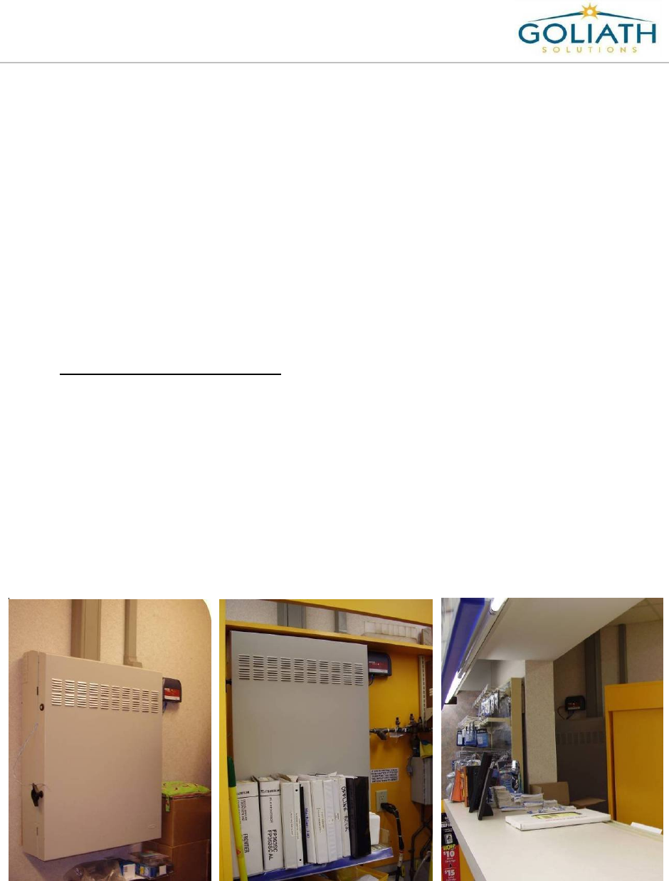
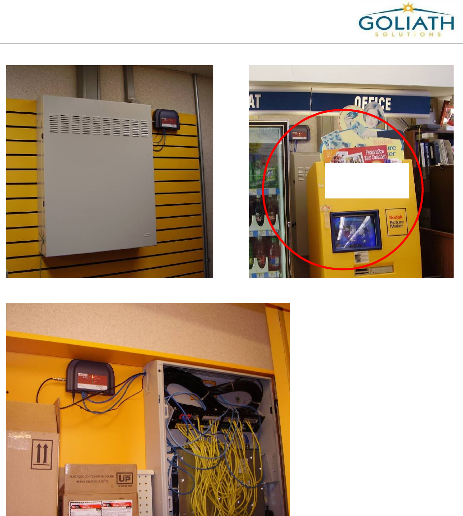
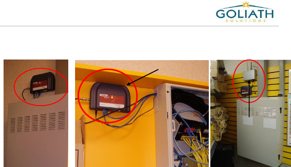
Determine CMU Installation Location:
1) Check the Photo department for the Secondary Communications cabinet (also known
as the Catalina cabinet). The cabinet may be mounted on the wall or on the wall
inside the yellow storage closet located in the Photo department. If the Catalina
cabinet is not found in Photo, then look around the store and try to find the cabinet;
most stores have a Catalina cabinet. Other locations where the cabinet may be
located are:
Break room
Electric room
Stock room
Tech room
Hallways
Behind a photo machine
Managers Office
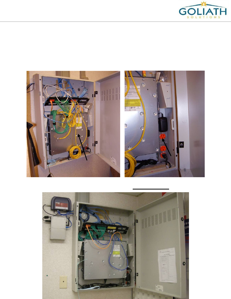
Examples - Wall Mounted Catalina Cabinets in the Photo Department
Catalina Cabinet
located inside
yellow storage
closet
Walgreens Installation Guide
G-1-2002-2B
Walgreens Installation Guide 2B.doc
Use or disclosure of this document is covered under the Non-Disclosure Agreement executed between the reader and Goliath Solutions,
LLC. This document and the information contained herein are privileged and should only be viewed by expressly authorized parties.
5/27/2008 Page: 2-6
Catalina Cabinet
behind the
photo machine
Network cables run through the wall
into the back of the Catalina cabinet.
Walgreens Installation Guide
G-1-2002-2B
Walgreens Installation Guide 2B.doc
Use or disclosure of this document is covered under the Non-Disclosure Agreement executed between the reader and Goliath Solutions,
LLC. This document and the information contained herein are privileged and should only be viewed by expressly authorized parties.
5/27/2008 Page: 2-7
2) If the store has a Catalina Cabinet then go to step 3, otherwise the CMU will be
located by the Communications Cabinet in the Pharmacy. Only enter the Pharmacy
if there is no Catalina Cabinet in the store. Notify the highest available level of
Store Management that you will need access to the Pharmacy. When in the
pharmacy the CIT must be accompanied by a Pharmacist that is on duty at all
times.
a) Minimize the time spent in the Pharmacy. Be very careful working in or near the
Communications cabinet and do not disconnect any network or power cables. This
cabinet is the heart of the stores communications system.
b) Locate the communications cabinet in the Pharmacy. Frequently the cabinet is
located near the entrance into the Pharmacy. The Pharmacist should be able to
help the CIT locate the cabinet if you don’t see it.
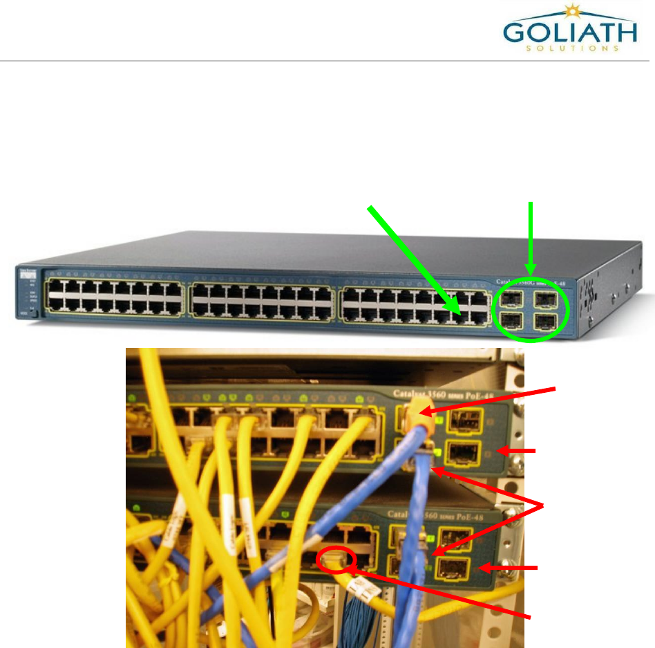
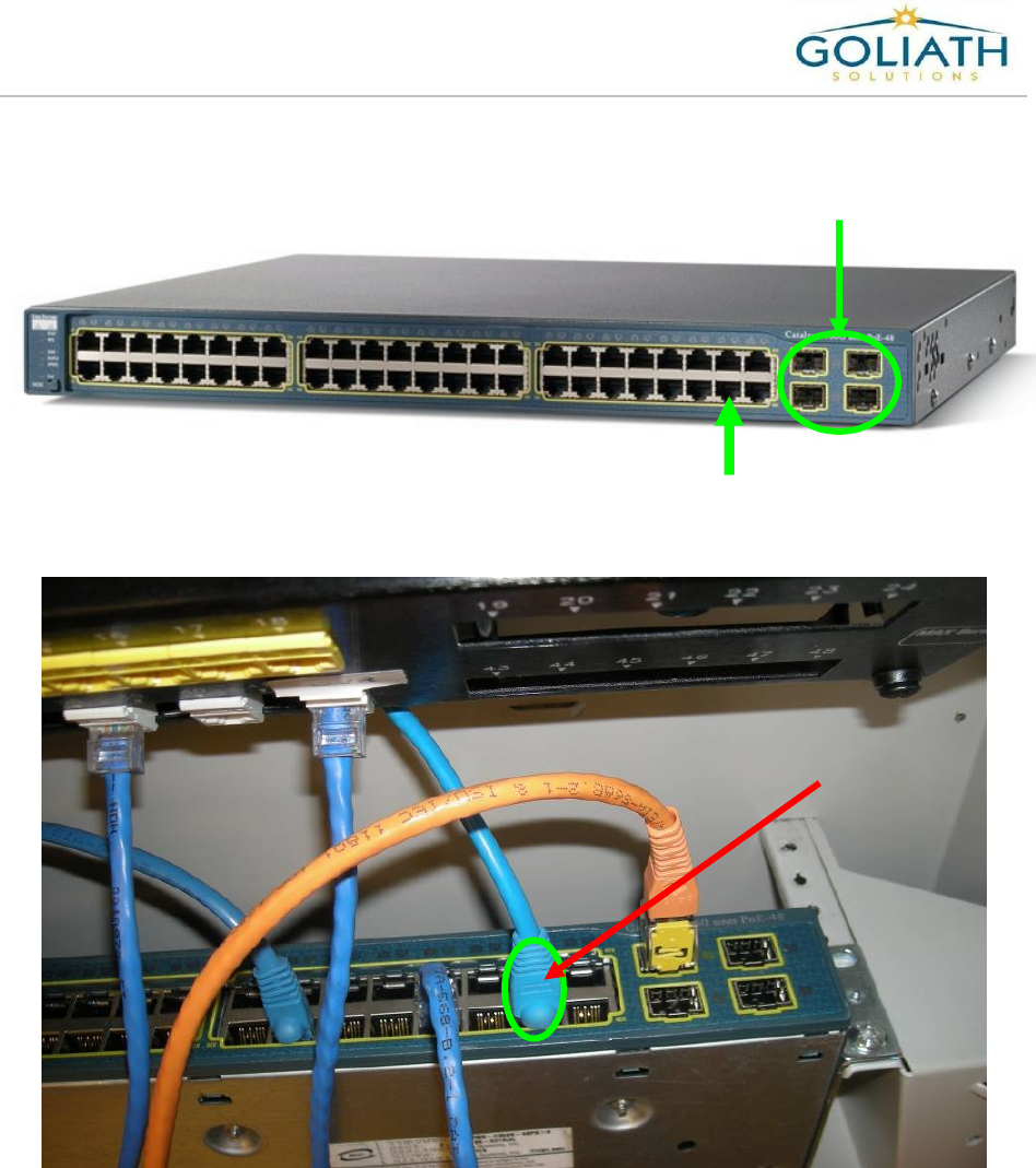
c) Open the communication cabinet and then locate the network switch or switches.
Most of the time the store will have one or two 48 port switches. The following are
the designated ports for Goliath:
If there is only one switch, Goliath will use port 46 on that switch.
If there are 2 switches, then Goliath will use port 46 on switch 2.
oTo determine switch 2, look for the orange patch cable running from the
patch panel (normally port one on the patch panel) to one of the switches.
The patch cable will be plugged into one of the 4 ports highlighted in the
picture below. On occasion the cable can be a different color. Only one
orange patch cable should be used. The switch that the orange patch
cable is plugged into is switch 1. The other switch which would be daisy
chained to switch 1 is switch 2. Switch 2 will not be connected to the patch
panel. Frequently a red patch cable is used to connect Switch 1 and 2.
If there are more than 2 switches or the designated port on the switch is not
available, then contact the Help Desk at the completion of the Pre-Installation
survey.
Switches
Walgreens Installation Guide
G-1-2002-2B
Walgreens Installation Guide 2B.doc
Use or disclosure of this document is covered under the Non-Disclosure Agreement executed between the reader and Goliath Solutions,
LLC. This document and the information contained herein are privileged and should only be viewed by expressly authorized parties.
5/27/2008 Page: 2-8
d) Validate that the port designated for Goliath is available on the switch.
e) Determine if there is a dedicated uninterrupted 24-hour power source available by
the communications cabinet. Do not use power strips or UPS units. The power
supply must be able to reach the CMU at its designated location and the power
source.
Port 46
on the
48 Port Switch
Ports only used to
connect switches
together or to the
patch panel.
Port 46
Switch 2
Switch 1
Patch
cable with
orange cap runs
to the patch
panel.
Patch Cable
connecting
Switch 1 to
Switch 2
Two 48 port switches
inside of the
Communication
Cabinet in the
Pharmacy
Walgreens Installation Guide
G-1-2002-2B
Walgreens Installation Guide 2B.doc
Use or disclosure of this document is covered under the Non-Disclosure Agreement executed between the reader and Goliath Solutions,
LLC. This document and the information contained herein are privileged and should only be viewed by expressly authorized parties.
5/27/2008 Page: 2-9
f) If the above conditions are present, then determine a location on the wall either
inside of the cabinet on the back wall or on the wall next to the cabinet to mount
the CMU. Next to the cabinet is the preferred location. The CMU should be at
eye level or above. If power or a designated port on the patch panel is not
available then contact the Help Desk at the completion of the Pre-installation
survey.
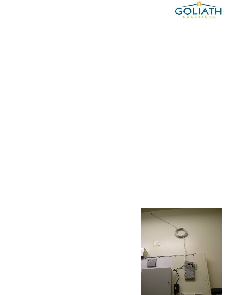
g) If power is not available for the MEU by the front security screen, then determine if
the 110’ power cable can be pulled into the pharmacy. The 110’ power cable must
use the same entry point and method into the communications cabinet as the
network cables.
h) Proceed to Determine the Primary MEU location.
CMU mounted on
the back wall
inside of the
communications
cabinet.
Power Supply
mounted on the back
wall inside of the
communications
cabinet.
Walgreens Installation Guide
G-1-2002-2B
Walgreens Installation Guide 2B.doc
Use or disclosure of this document is covered under the Non-Disclosure Agreement executed between the reader and Goliath Solutions,
LLC. This document and the information contained herein are privileged and should only be viewed by expressly authorized parties.
5/27/2008 Page: 2-10
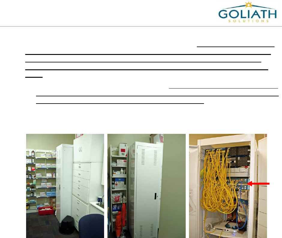
3) Open the Catalina cabinet and validate the following information:
Determine if the cabinet has either a 48 port switch or two 24 port switches.
oIf the switch is a 48 port, then validate that port 46 is open for Goliath.
oIf there are two 24 port switches, then validate that port 22 on switch 2 is open
for Goliath.
Is there an open 24-hour uninterrupted power outlet is available in the cabinet?
a) The following pictures show examples of a 48 port switch in the Catalina Cabinet.
Switch
Open
Uninterrupted
Power outlet
Walgreens Installation Guide
G-1-2002-2B
Walgreens Installation Guide 2B.doc
Use or disclosure of this document is covered under the Non-Disclosure Agreement executed between the reader and Goliath Solutions,
LLC. This document and the information contained herein are privileged and should only be viewed by expressly authorized parties.
5/27/2008 Page: 2-11
Port 46
Port 46
on the
48 Port Switch
Ports on
ly used to
connect switches
together or to the
patch panel.
Walgreens Installation Guide
G-1-2002-2B
Walgreens Installation Guide 2B.doc
Use or disclosure of this document is covered under the Non-Disclosure Agreement executed between the reader and Goliath Solutions,
LLC. This document and the information contained herein are privileged and should only be viewed by expressly authorized parties.
5/27/2008 Page: 2-12
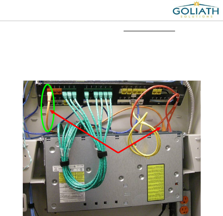
b) The following pictures show examples of two 24 port switches in a Catalina
Cabinet. The CMU patch cable will always plug into port 22 on switch 2.
oTo determine switch 2, look for the orange patch cable running from the patch
panel to one of the switches. Sometimes the cable can be a different color.
Only one orange patch cable should be used. The switch that the orange
patch cable is plugged into is switch 1. The other switch which would be daisy
chained to switch 1 is switch 2. Switch 2 will not be connected to the patch
panel. Frequently a red patch cable is used to connect Switch 1 and 2.
Orange
Patch
Cable
Walgreens Installation Guide
G-1-2002-2B
Walgreens Installation Guide 2B.doc
Use or disclosure of this document is covered under the Non-Disclosure Agreement executed between the reader and Goliath Solutions,
LLC. This document and the information contained herein are privileged and should only be viewed by expressly authorized parties.
5/27/2008 Page: 2-13
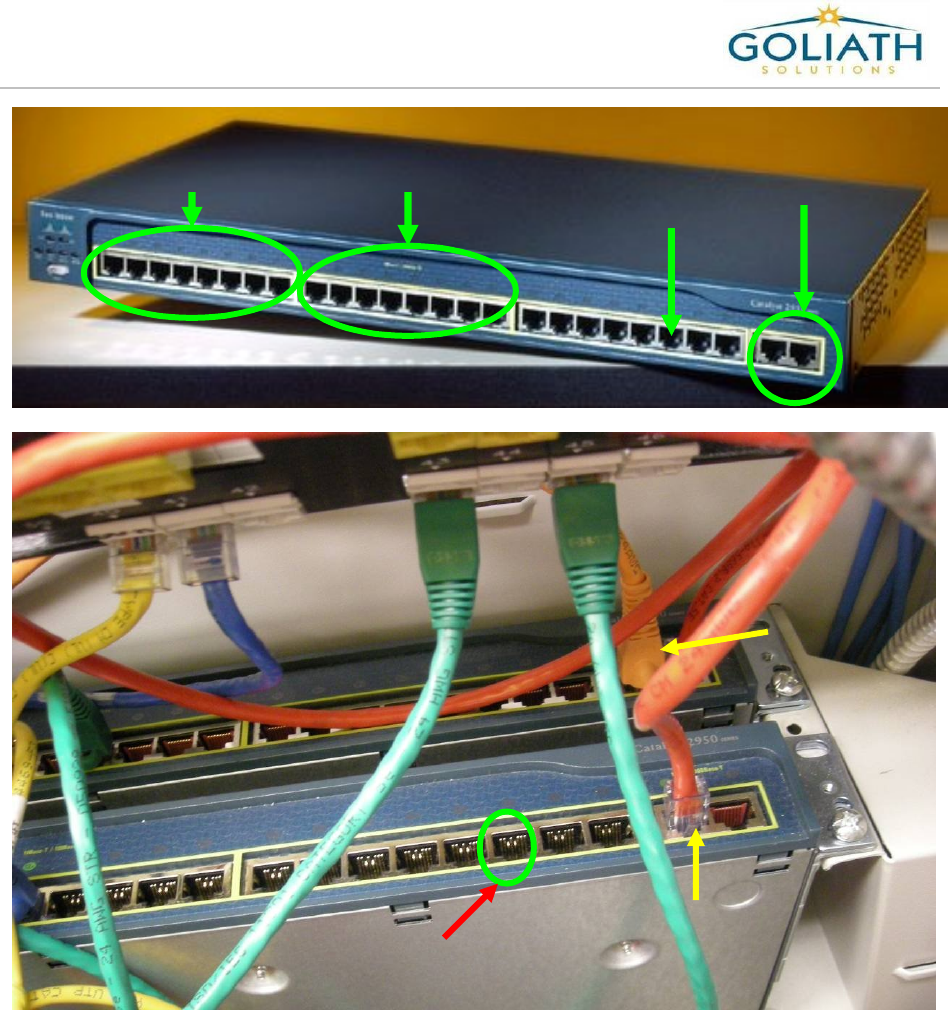
Orange Patch
Cable connected
to Switch 1
Port 22 on Switch 2
Ports 1-8 Ports 9-16
Port 22
Ports only used to
connect switches
together or to the
patch panel.
Patch cable
connecting
Switch 1 and
Switch 2
Walgreens Installation Guide
G-1-2002-2B
Walgreens Installation Guide 2B.doc
Use or disclosure of this document is covered under the Non-Disclosure Agreement executed between the reader and Goliath Solutions,
LLC. This document and the information contained herein are privileged and should only be viewed by expressly authorized parties.
5/27/2008 Page: 2-14
4) Determine the location to mount the CMU on the wall. The CMU will normally be
mounted near the INDYME device. Review the following criteria to determine the
location.
The CMU should be mounted about eye level or above the cabinet.
The CMU should not be mounted over 1 foot higher than the top of the cabinet.
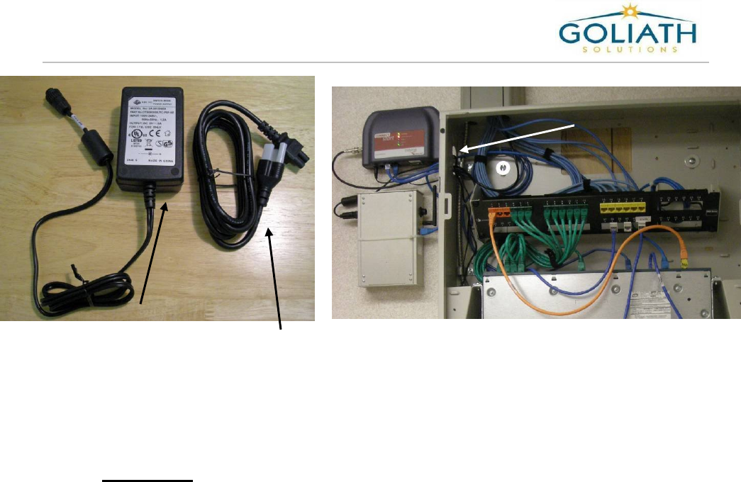
The CMU/MEU power supply brick must be inside the Catalina cabinet.
Determine a knock out hole on either side of the cabinet to open. The knock out
must be large enough to run the low voltage cable from the power supply, a
network patch cable and if needed the CMU/MEU power cable through the hole.
The diameter of the knock out hole is 1 1/8 inches.
The CMU should be 36 inches or less from the knock out hole on the Catalina
cabinet. If needed, the12 foot power extension cable from the Hot Spare Kit can
be used.
The provided network patch cable must reach the designated port on the switch.
INDYME Device
CMU
Walgreens Installation Guide
G-1-2002-2B
Walgreens Installation Guide 2B.doc
Use or disclosure of this document is covered under the Non-Disclosure Agreement executed between the reader and Goliath Solutions,
LLC. This document and the information contained herein are privileged and should only be viewed by expressly authorized parties.
5/27/2008 Page: 2-15
REMEMBER: BOTH A DEDICATED UNINTERRUPTED POWER OUTLET AND A
NETWORK CONNECTION MUST BE PRESENT AT THE CMU
LOCATION!
CMU/MEU
low voltage
cable and
power supply
(Power Brick)
6 foot power
cable for
power supply
Knock Out hole

Walgreens Installation Guide
G-1-2002-2B
Walgreens Installation Guide 2B.doc
Use or disclosure of this document is covered under the Non-Disclosure Agreement executed between the reader and Goliath Solutions,
LLC. This document and the information contained herein are privileged and should only be viewed by expressly authorized parties.
5/27/2008 Page: 2-16
Determine the Primary MEU Installation Location:
The MEU location marked on the store floor plan is only a suggested location. The actual
location is determined during the Pre-installation Store Survey by reviewing the following
criteria:
1) The MEU power source. The power source for the MEU must be an open
uninterrupted 24-hour power source. It can not be plugged into a cube tap, power
strip or a UPS used by a LAN cabinet or computer. The MEU must be able to reach
this location with the 110 foot CMU/MEU power cable. The following are the approved
locations for the MEU power.
The first choice is an open outlet in the ceiling near the security screen that is
located by the front entrance of the store. Use this location if it is available. It is a
good idea to check this location for power as the first step in the Pre-
installation survey.
The second choice is the output power port on the back of the CMU.
oDetermine if there are any issues that would prevent pulling the CMU/MEU
power cable to this location.
oThe CMU/MEU power cable must use the same entry method into the Catalina
or Communications cabinet as the network cables.
oIn a Catalina cabinet the 110 foot power cable must exit out of the same knock
out hole as the CMU power cable and network patch cable.
oA second power supply will not be required if the MEU gets power from the
output power port on the CMU.
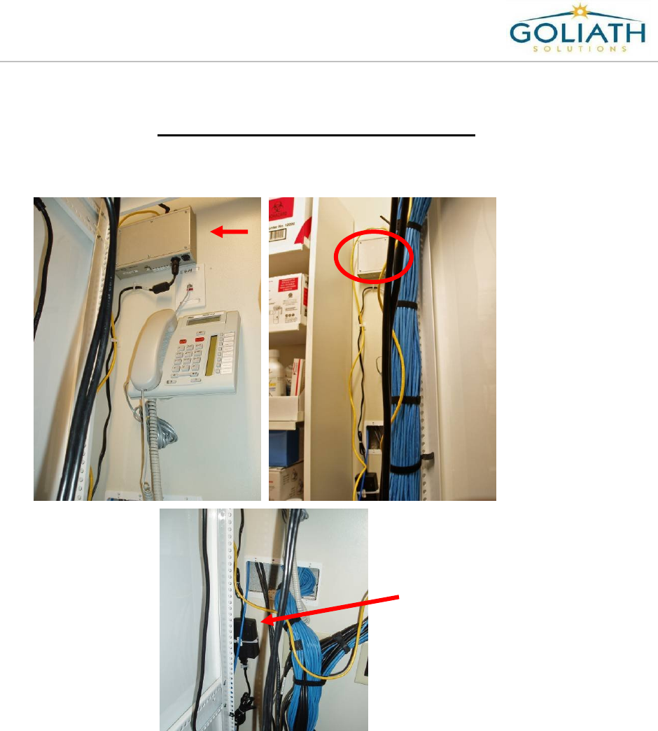
The last option is by the Communications area in the store. The store will normally
have either a tech room or a phone block located in the stock room. This area
normally has open uninterrupted 24-hour power outlets. Only use this area if the
first two options are not available. This location must be approved by the Help
Desk prior to beginning the installation.
Note: Tech Rooms are not present in every store. Many stores instead of having a
Tech Room will have the main communication cabinet located in the Pharmacy
and the phone block located in the stock room. Do not go into the Pharmacy
unless the CMU will be installed in the Pharmacy. Follow the procedures
of Pharmacy access defined in the Walgreens Environment section in
chapter 1.
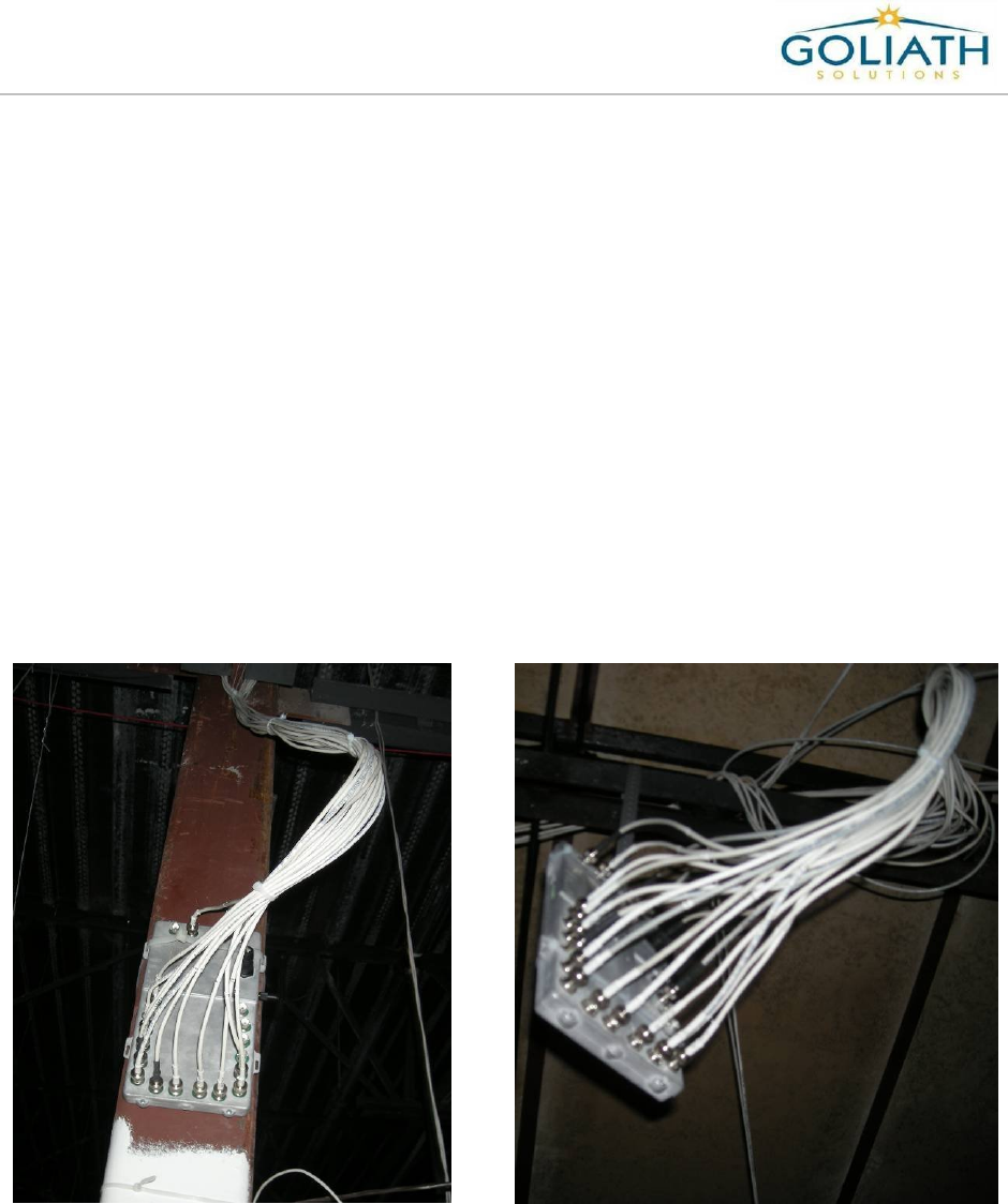
2) Determine the location and the mounting method for the MEU. The MEU over the
sales floor may be either mounted on a post in the ceiling or suspended from the roof
girders in the ceiling. The preferred mounting method is a post mount. Normally
the posts are located near the center of the sales floor, typically at aisle 4/5 or 8/9 and
towards the back half of store.
Walgreens Installation Guide
G-1-2002-2B
Walgreens Installation Guide 2B.doc
Use or disclosure of this document is covered under the Non-Disclosure Agreement executed between the reader and Goliath Solutions,
LLC. This document and the information contained herein are privileged and should only be viewed by expressly authorized parties.
5/27/2008 Page: 2-17
3) Use the following criteria to determine the MEU location and mounting method.
The location and distance from the MEU to its power source.
The distance from the MEU to all of the Tx/ATA and Rx/ARA antennas.
oCable length limitations are:
110 foot for the power cable
110 foot for the Tx/ATA
135 foot for the Rx/ARA
Minimal service loops must be at the MEU and antenna locations.
Access to the stock room for cables.
Access in the ceiling to the designated location for the MEU.
Access in the ceiling for cable pulls from the antennas to the MEU.
Do not remove a specialty cut tile if there is a high chance of damaging it.
Access to the preferred location may be prevented by obstructions in the ceiling
such as AC ductwork or sprinkler heads.
The designated location must allow for access to the ports on the MEU and reset
controls.
The location for the MEU should never be directly over the Middle aisle or Power
aisle.
Post
Mount
Suspended
Mount
Walgreens Installation Guide
G-1-2002-2B
Walgreens Installation Guide 2B.doc
Use or disclosure of this document is covered under the Non-Disclosure Agreement executed between the reader and Goliath Solutions,
LLC. This document and the information contained herein are privileged and should only be viewed by expressly authorized parties.
5/27/2008 Page: 2-18
Please refer to the following table for suggested locations for the MEU. The primary MEU
must always be mounted or suspended in the ceiling near the center of the sales
floor, but never directly over the middle aisle.
MEU Power Location Mounting
Method
Suggested MEU Location near the
Middle aisle
Front Security Camera Post Mount Post normally found near aisle 4 or 5.
CMU output power port
in Photo
Post Mount Post normally found near aisle 8 or 9.
Communications Area Post Mount Post closest to the Communications area.
Front Security Camera Suspended
Mount
Suspended over aisle 4 or 5 near the
middle aisle.
CMU output power port
in Photo
Suspended
Mount
Suspended over aisle 7 or 8 near the
middle aisle
Communications Area Suspended
Mount
Suspended near the center of the sales
floor skewed towards power location.
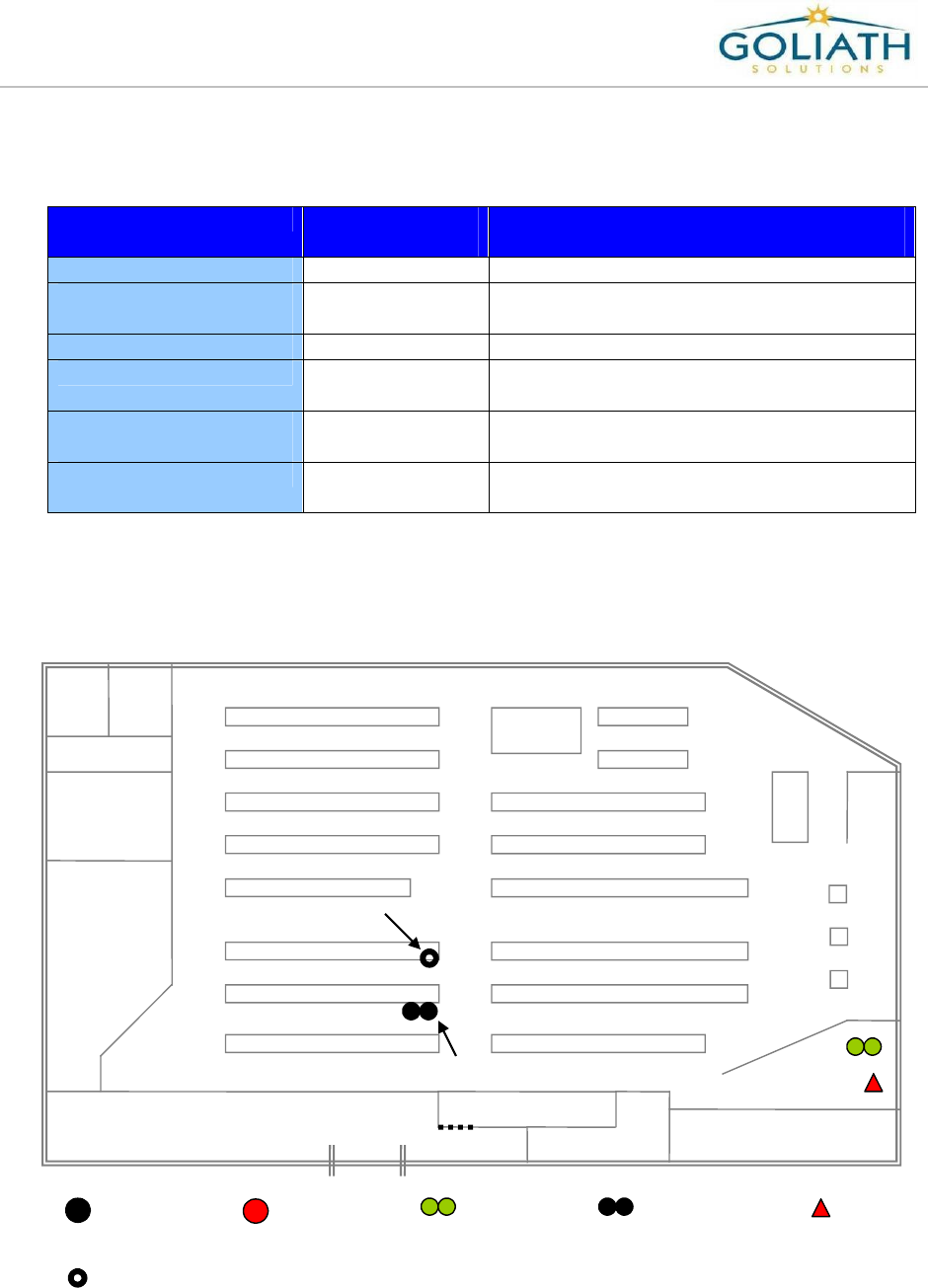
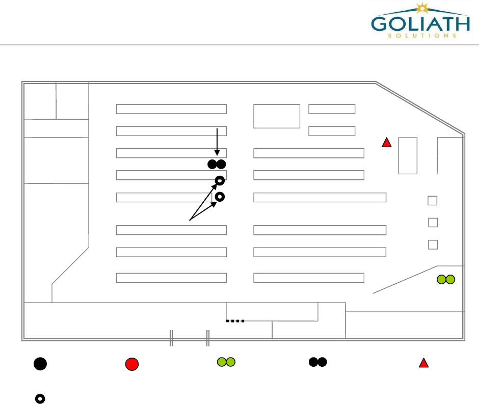
4) The Following two diagrams show examples of how the MEU location will be adjusted
based upon the location of the MEU power source and the distance from each Tx/ATA
and Rx/ARA antenna.
Restrooms
Employee
Room
Pharmacy
Stock Room Phone Block
Coolers
Employee Lockers
Photo
Front Entrance
Cosmetics
Registers
Receiving
Door
Aisle 1
Aisle 2
Aisle 3
Aisle 4
Aisle 5
Aisle 6
Aisle 7
Aisle 8
Aisle 9
Middle Aisle
Front of Store
Back of Store
Preferred MEU Location
Potential Alternate
MEU Location
=Receiver =Transmitter =CMU =MEU =Power
=Potential Alternate MEU Locations
Walgreens Installation Guide
G-1-2002-2B
Walgreens Installation Guide 2B.doc
Use or disclosure of this document is covered under the Non-Disclosure Agreement executed between the reader and Goliath Solutions,
LLC. This document and the information contained herein are privileged and should only be viewed by expressly authorized parties.
5/27/2008 Page: 2-19
MEU Location Diagram
5) Determine the ceiling height of the drop ceiling in the store and the height of the roof
iron above the ceiling. Ceiling heights are normally 12’, 13’ and 14’. You can estimate
the ceiling height based on the height of your ladder or use a tape measure to get the
exact height. Estimate the approximate height of the roof iron above the ceiling grid.
Record this information as it will be required by the Help Desk on your store check-out
call.
Restrooms
Employee
Room
Pharmacy
Stock Room Phone Block
Coolers
Employee Lockers
Photo
Front Entrance
Cosmetics
Registers
Receiving
Door
Aisle 1
Aisle 2
Aisle 3
Aisle 4
Aisle 5
Aisle 6
Aisle 7
Aisle 8
Aisle 9
Middle Aisle
Front of Store
Back of Store
Preferred MEU Location
Potential Alternate
MEU Locations
=Receiver =Transmitter =CMU =MEU =Power
=Potential Alternate MEU Locations
Walgreens Installation Guide
G-1-2002-2B
Walgreens Installation Guide 2B.doc
Use or disclosure of this document is covered under the Non-Disclosure Agreement executed between the reader and Goliath Solutions,
LLC. This document and the information contained herein are privileged and should only be viewed by expressly authorized parties.
5/27/2008 Page: 2-20
Determine if a Second MEU is required:
Most stores will require only one MEU. But some exception stores will require a second
MEU. If a second MEU is required it will normally be located in the stock room. Stores
with a basement or second floor stock room will frequently require a second MEU. The
primary reasons a second MEU will be required are:
The coaxial cables will exceed the maximum supported length to reach the
designated locations for the Tx/ATA and Rx/ARA in the stock room from the
primary MEU.
There are no access points to pull the cables into the stock room and an access
point can not be cut.
The sales floor is very large or has an unusual store floor plan that prevents the
coaxial cables from reaching the primary MEU from all designated Tx/ATA and
Rx/ARA antenna locations within the maximum supported cable lengths. A second
MEU will be required to complete the sales floor coverage.
A second MEU may be listed on the store floor plan. If a second MEU is listed on the floor
plan, then determine during the survey if it is actually required. If it is not required notify
the Help Desk at the completion of the Pre-installation survey and they will determine how
to proceed with the second MEU.
A second MEU may not be listed on the store floor plan, but if it is determined during the
survey that a second MEU is required then notify the Help Desk. The Help Desk will
advise the CIT on how to proceed.
If a second MEU is required, use the same criteria as the primary MEU to determine its
actual location. The location designated on the store floor plan is only a best guess. The
actual location can not be determined without seeing the conditions present in the store.
Dedicated 24-hour uninterrupted power for
the second MEU can normally be found in an
electric room or by the phone block which is
commonly located in the stock room.
The second MEU must be mounted with one
of the following methods:
oPost mount
oSuspended mount
oWall mounted (only valid in a stock room)
Wall
Mounted
MEU

Walgreens Installation Guide
G-1-2002-2B
Walgreens Installation Guide 2B.doc
Use or disclosure of this document is covered under the Non-Disclosure Agreement executed between the reader and Goliath Solutions,
LLC. This document and the information contained herein are privileged and should only be viewed by expressly authorized parties.
5/27/2008 Page: 2-21
Determine the Tx/ATA and Rx/ARA Antennae Placement:
1) Using the “Pre-installation Survey Check-list” and the store floor plan, walk the store
and determine the location for the placement of the Tx/ATA and Rx/ARA antennae for
both the sales floor and the stock room. Refer to “Appendix A - Antenna Placement”
of this guide for more detailed information on the placement of each antennae.
2) The location for each Tx/ATA and Rx/ARA marked on the floor plan is the
recommended location for each antenna. The actual location is determined by issues
found at the suggested location during the survey. The actual location normally should
not be more than one tile over from the designated location. The following rules must
be used to determine the actual antennae placement.
The Tx/ATA antenna must have a clean line of sight to the floor. It can not be over
shelves or display tables.
The Rx/ARA antenna should have a clean line of sight to the floor, but it can be
over a display table. It can not be over shelves.
Tx/ATA antennas over the sales floor must be installed on a full ceiling tile.
Rx/ARA antennas can be installed on a partial tile but the tile must be square or
rectangular, it can not be installed on a specialty cut tile. Install on a full tile if
possible.
Nothing else can be installed on the same tile as a Tx/ATA or Rx/ARA. This
includes but is not limited to:
oA/C vents
oSprinkler heads
oSecurity cameras
oSecurity screens
oEmergency lighting
oSpeakers
Each antenna must be a minimum of 10 feet from another antenna.
If the location for Rx-5 and Rx-9 must be adjusted, skew it towards aisle 1.
If the location for Rx-8 and Rx-12 must be adjusted, skew it towards the last aisle;
normally that is aisle 9 or 10.
There must be access in the ceiling to install the antenna and to meet the
installation requirements for that antenna.
If there is a problem determining the location of the antenna, then check with the
Help Desk.
3) When reviewing the locations of the Rx/ARA antennas along the back wall of the store,
look to see if mirrors are present. If mirrors are present; refer to Back Wall Antenna
Placement Issues found in Appendix A - Antenna Placement. This section
describes how mirrors affect the placement of Rx-9, Rx-10, Rx-11 and Rx-12 along the
back of the store.
Walgreens Installation Guide
G-1-2002-2B
Walgreens Installation Guide 2B.doc
Use or disclosure of this document is covered under the Non-Disclosure Agreement executed between the reader and Goliath Solutions,
LLC. This document and the information contained herein are privileged and should only be viewed by expressly authorized parties.
5/27/2008 Page: 2-22
4) Mark the location of the Tx/ATA or Rx/ARA antennae on the floor directly below the
selected ceiling tile location or the roof iron.
Use the assigned antenna number found on the store floor plan for that location
when marking the floor.
When marking the location on the floor, you must use painters tape. Write the
antenna’s number on the painters tape prior to placing on the floor. You will be
required to remove the painters tape from the floor during site clean up. Never
write on the floor. Always used painter tape. Never use electric tape or duct
tape to mark the location on the floor. Electric tape and duct tape will damage
the floor. Painters tape does not leave marks.
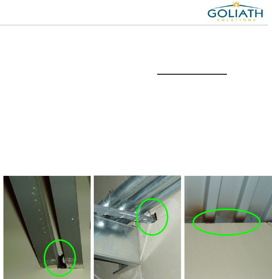
5) Determine the access point to pull the coaxial cables into the stock room from the
sales floor. Use existing openings such as may be found around the bottom of the roof
girder or over the top of a roof girder. Never use an existing opening if power
conduit or water pipes go through that opening. You may have to cut a new
opening in the wall. If it is not possible to get the cables into the stock room from the
sales floor, then a second MEU may be required. If a second MEU is required contact
the Help Desk.
6) Determine if a firewall is present between the sales floor and the stock room. If a
firewall is present then a firewall conduit sleeve is required to pull the cables into the
stock room. You must also use Fire Stop (caulk) to seal around the sleeve.
Between the sheet
rock wall and the
ceiling